9.7. Advanced Options 
9.7.1. Variables
-
Primary Workpiece (PDIE)
-
Use original additive rule for transformation kinetics (TRANS)
9.7.2.Error Tolerances
-
Contact release method (CNTERR)
-
Geometry error (GEOERR)
9.7.3. User defined variables (USRDEF)
9.7.4. Contact
-
Penalty
-
Conforming Coupling
-
Augmented Lagrangian
-
Multiple deforming Method (MULDEF)
Fully coupled
Loosely coupled
No geometry update
-
Deformation calculation
-
Thermal calculation
9.7.5. Frequency
9.7.6. Nodal Oscillations (OSCTRL)
-
Corner oscillations
9.7.7. Object Copy
For Simulation control Advanced variables settings see Fig. 9.7.1.

Advanced variables window
Variables [2D, 3D]
Current Global Time/Current Local Time (TNOW)
This (TNOW) specifies the values of global process time and the local process time. (See Fig. 9.7.1. ). The global time is the time since the beginning of the problem, and should never be reset. Local time is a parameter that can be reset by the user. The global time should not be reset during a simulation as the post-processor uses this time for many post processing operations. Below the local and global time definitions is a selector box that determines which time is to be used for time dependent functions such as movement controls. The default is global time, however, the time dependent functions can also be made a function of local time.
Primary Workpiece (PDIE)
This (PDIE) parameter allows the user to specify the workpiece as an object that must not possess rigid body motion. (See Fig. 9.7.1. ) If the body does not deform, the simulation will stop. One purpose of this function is to prevent a rolling simulation from continuing past the rolled length of material.
Use original additive rule for transformation kinetics (TRANS)
We have improved the transformation kinetics (TRANS) rule from version 6.0. With the new version, multiple transformations can occur at the same time and temperature for a given material. If the user does not want to use this new rule and wants to use the previous one, checking this box will allow this. (See Fig. 9.7.1.)
Error Tolerances [2D, 3D]
- Contact release method (CNTERR) [2D] :
In certain cases, the present contact algorithm does not release nodes that are touching a master surface within the time step. This option CNTERR allows the contact condition for a slave node to be released if it moves away from the master boundary by a prescribed distance. This value can be used as an alternative to the sliding error (SLDERR). (See Fig. 9.7.2.)
- Geometry error (GEOERR) [2D, 3D]
This GEOERR value is an estimate of the error between discretized objects. The default value for this is sufficient for most of the general applications. (See Fig. 9.7.2.)
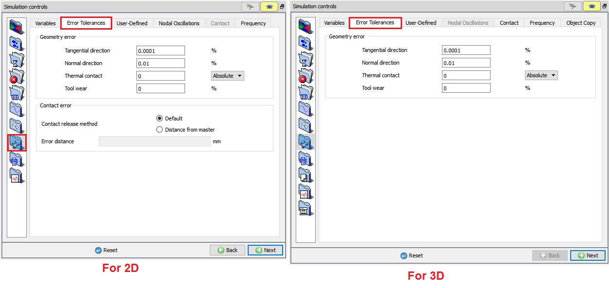
Advanced Error tolerances window
User defined variables (USRDEF) [2D, 3D]
User defined variables (USRDEF) are 80 character string variables which are passed to user defined subroutines. Refer to the Chapter 56. User Routines for more information on how to use these variables. (See Fig. 9.7.3.)

User defined values
Contact [3D]
From DEFORM-V12 Contact tab has been added under Advanced page, Contact method ( CNTMTH) which was available for 3D object in Inter - object relations page has been moved to this page. Now we have 3 types of Contact methods:
- Penalty
- Conforming coupling
-
Augmented Lagrangian
- Penalty
Penalty method ( Fig. 9.7.4.) is the main approach for handling contact for all the deforming objects to handle die contact. However, for rigid plastic models with multiple deforming objects in contact or self-contact conformal coupling is also available.
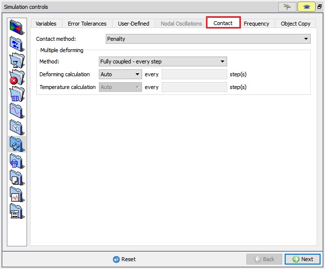
Penalty - Contact method
- Conforming Coupling
Conforming coupling essentially handles contact by first generating contact elements automatically across the contacting mesh systems. For models involving rotational symmetry conforming coupling is used by default.
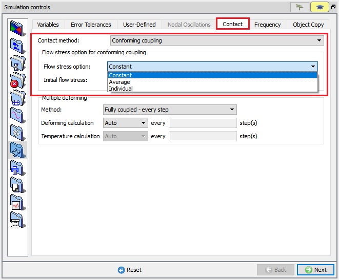
Conforming Coupling - Contact method
- Augmented Lagrangian
New Augmented Lagrangian contact (ALC) method has been introduced from v12 for faster computation for models involving multiple deforming objects like coupled die stress (Elastic Dies – Rigid Plastic workpiece, Elastic Dies – Elasto-Plastic Workpiece). ALC method is not sensitive to penalty number and performs well with iterative CG solver. ALC method can be used with both Newton - Raphson and Direct methods but models involving elasto-pastic object requires Newton - Raphson method. ALC works better with CG solver and for Large models involving multiple deforming objects or elastic dies.
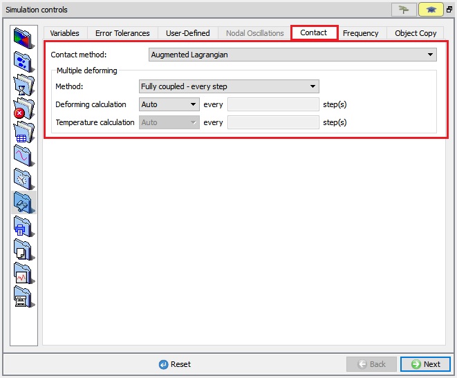
Augmented Lagrangian - Contact method
- Multiple deforming Method (MULDEF)
In Older versions to simulate Coupled die stress analysis we need to create DEF_LCDSTS.DAT file, now these options can be defined in GUI itself from DEFORM-V12 as shown in Fig. 9.7.7.
- Fully coupled
- Loosely coupled
- No geometry update
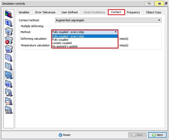
Multiple Deforming methods
-
Fully coupled : Fully coupled means the deflection of the tool is reflected in the deformation of the workpiece at the current step. In general, Fully coupled is the most accurate, and most computationally expensive. No geometry update option is the least computationally expensive, and offers the most simplification of the process.
-
Loosely coupled : When this option is selected the stresses are calculated in the tool, but the updated die geometry will not be reflected in workpiece deformation until the next step. Loosely coupled is more numerically efficient than Fully coupled but may cause some inconsistencies in workpiece surface position (and therefore workpiece volume) if the change in the die shape is substantial.
-
No geometry update : In No geometry update only stress is calculated in the die, but the die geometry is never updated. If the user interest is only tool stress, No geometry update option is generally adequate. If tool deflection is important then Fully coupled or Loosely coupled should be selected.
-
Deformation calculation
User can define the interval of steps for calculating Deformation on tool by using user-defined option. By default, Auto step will be selected, so Deformation calculations are done at every step.
- Thermal calculation
User can define the interval of steps for Thermal calculations on tool by using user-defined option. By default, Auto step will be selected, so thermal calculations are done at every step.
Frequency [2D,3D]
Under Frequency (see Fig. 9.7.8.), user can define calcuation control value for Explicit solver, Maxwell equation solving, viewfactor calculation and Yield surface calculation.
Even for ALE steady state simulation, user can define Strain update method and Temperature update method.

3D Frequency Window
Nodal Oscillations [2D]
For Simulation control Advanced Nodal oscillations (OSCTRL) settings see Fig. 9.7.9.
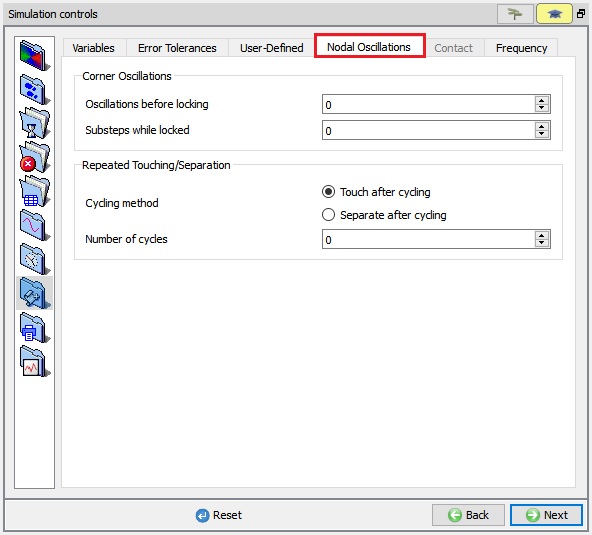
2D Nodal Oscillations Window
- Corner oscillations
Corner oscillation controls are used to control oscillation of a node between adjacent line segments of a surface. If the number of oscillations exceeds the limit, the node will be locked for a fixed number of sub steps.
- Repeated touching / separating
When slave nodes touch and separate from a master surface, after two oscillations the nodes are made to touch for the sub step. The touching/separating control can be used to make the node separate from the surface for the sub step after a specified number of oscillations.
Object Copy [3D]
To replace the DEF_VIEWSYM.DAT file Object copy (OBJCPY) option has been developed under Simulation controls (See Fig. 9.7.10.). User can select the object arranged type (By Translating or By Mirroring)
By Translating: In Translatinn method user need to define the Distance vector value to copy object.
By Mirroring: In Mirroring method user need to define the Reference Point and Vector value respectively.
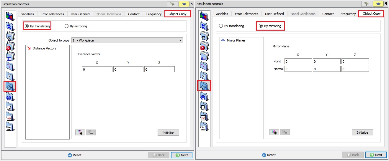
Object copy window
Related Topics:
9.1. Simulation type Settings
9.2. Defining Step
9.3. Stopping Controls
9.4. Remesh Criteria
9.5. Solver Settings
9.6. Process Conditions
9.8. Control Files
9.9. Thermomechanical variables