2D Boolean Operation Lab
1.1. Introduction
1.2. Creating new Problem
1.3. Adding 2D Forming operations
1.4. Importing Rib_web_SI.KEY file
1.5. Generating Database
1.6. Post-Processing the Results
1.7. Adding Boolean operation
1.8. Objects selection
1.9. Defining cutter geometry
1.10. Generating Database
Introduction
In this lab we are demonstrating how to setup the Boolean operation using Rib Web example keyfile to remove the flash in MO Wizard.
Creating new Problem
On a Windows machine , go to the ![]() button select DEFORM-v1x.xxx (.xxx indicates version number E.g. v14.0.2) and select DEFORM GUI Main vxx.xx from the menu. The DEFORM GUI Main window will appear.
button select DEFORM-v1x.xxx (.xxx indicates version number E.g. v14.0.2) and select DEFORM GUI Main vxx.xx from the menu. The DEFORM GUI Main window will appear.
Create a new problem either by selecting File ![]() New Problem or by clicking the New Problem
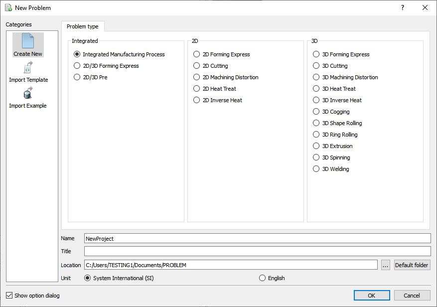
New Problem or by clicking the New Problem ![]() icon. The Problem Setup window will appear as shown in Fig. 2DBL1.1. Select “Integrated Manufacturing Process “ radio button and unit system as “SI “ radio button in unit field. Define Problem Name as “2D_Boolean_Lab “ and make sure the “Show option dialog” check box is turned on (if we do not turn on the “Show option dialog ” check box, then we will not get the New Project dialog in MO UI). Then click on
icon. The Problem Setup window will appear as shown in Fig. 2DBL1.1. Select “Integrated Manufacturing Process “ radio button and unit system as “SI “ radio button in unit field. Define Problem Name as “2D_Boolean_Lab “ and make sure the “Show option dialog” check box is turned on (if we do not turn on the “Show option dialog ” check box, then we will not get the New Project dialog in MO UI). Then click on ![]() button to open a new Problem using the Deform Integrated Manufacturing Process.
button to open a new Problem using the Deform Integrated Manufacturing Process.
Problem Location selection window
Adding 2D Forming operations
Multiple Operation wizard will open with new project called 2D_Boolean_Lab to setup the problem. Add 2D Forming operation from Operations list in Explorer. Operation can be added by clicking on ![]() button next to 2D Forming operation (see Fig. 2DBL1.2.) or user can also add the operation by dragging and dropping the operation into Operation Editor region.
button next to 2D Forming operation (see Fig. 2DBL1.2.) or user can also add the operation by dragging and dropping the operation into Operation Editor region.
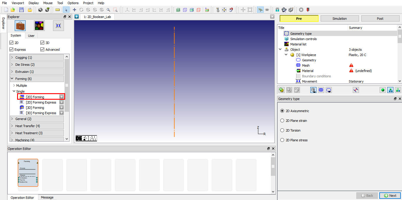
Added 2D Forming operation into Operation Editor
Importing Rib_web_SI.KEY file
Import Rib_web_SI.KEY file from DEFORM installation folder \2D\2D_Examples\SI\Forging Directory using ![]() icon. Click on
icon. Click on ![]() until DB generation page.
until DB generation page.
Generating Database
In Generate DB page. Click the ![]() button to have the program check to see if anything was missed in the problem setup.
button to have the program check to see if anything was missed in the problem setup.
Click on ![]() button to generate the database. When the program is done writing the database, switch to
button to generate the database. When the program is done writing the database, switch to ![]() tab to run simulation.
tab to run simulation.
Once the database has been generated, switch to the Simulation mode by clicking on ![]() button above the operation tree. Click on the
button above the operation tree. Click on the ![]() action label to open the Run Options dialog. Use the default Continue Run option to select “Continue from the last step ” (from step -1) option and then select the Simulation mode as Interactive and click on
action label to open the Run Options dialog. Use the default Continue Run option to select “Continue from the last step ” (from step -1) option and then select the Simulation mode as Interactive and click on ![]() button to run the simulation. As we click on
button to run the simulation. As we click on ![]() button simulation starts.
button simulation starts.
When the simulation is finished without any issues, the following message will be added to the end of the Message file:”NORMAL STOP: Simulation is completed and stopped at the user specified time step”.
Post-Processing the Results
After simulation has been completed, switch to ![]() tab to view results, MO post processor will open. Play through the steps to see the workpiece shape (see Fig. 2DBL1.3.).
tab to view results, MO post processor will open. Play through the steps to see the workpiece shape (see Fig. 2DBL1.3.).
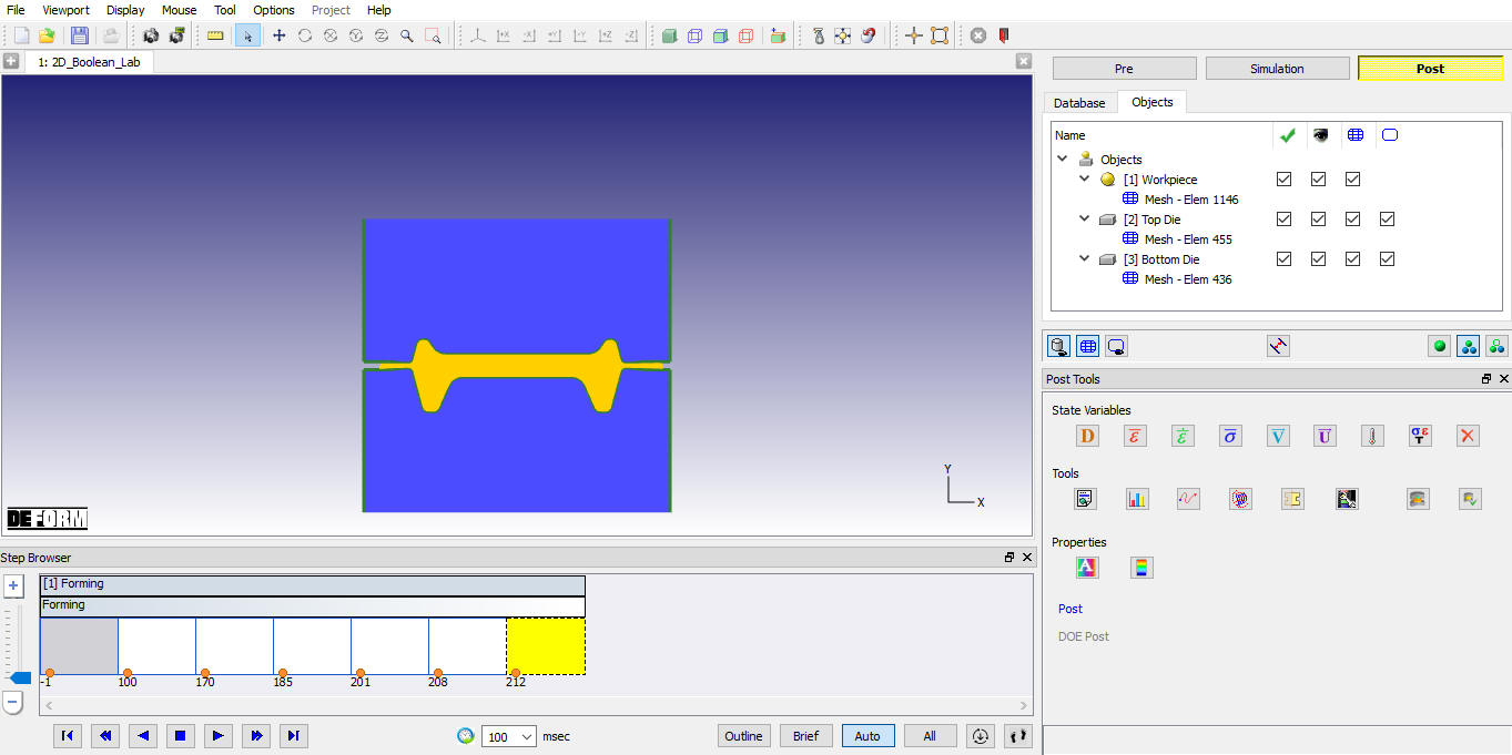
MO Postprocessor window
Adding Boolean operation
Click on ![]() tab, MO Pre processor will open.
tab, MO Pre processor will open.
In this operation we will be define the region to be Boolean at the flash region.
Add Boolean operator 2D from Operations list in Explorer. Click on Boolean operator 2D in operation editor (see Fig. 2DBL1.4.).
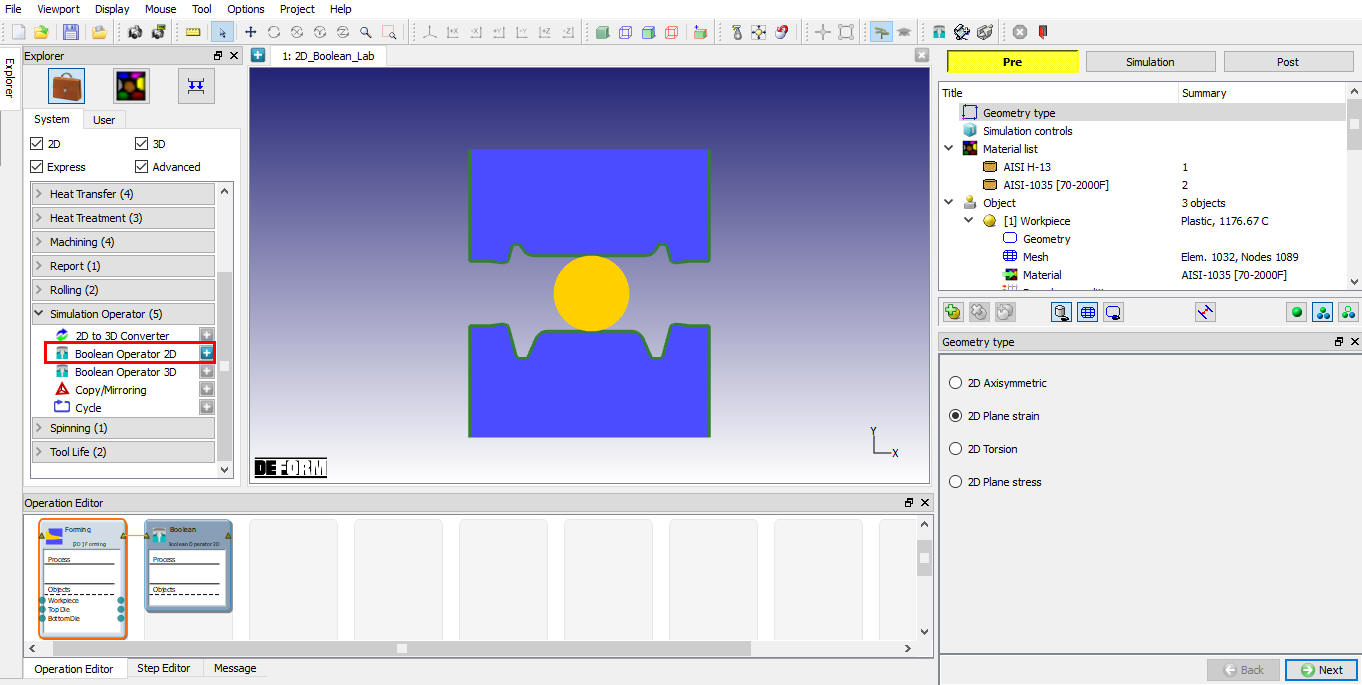
Adding Boolean operator 2D
Objects selection
By default workpiece will be transferred to Boolean operation. We can transfer the Dies objects if required using Right mouse menu “Pass object to Next operation” option. (See Fig. 2DBL1.5.).
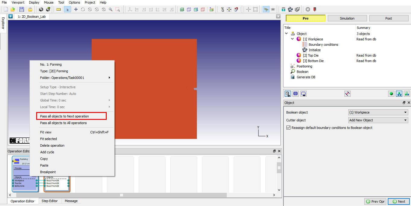
Passing object to Boolean operation
If user does not want the die to the Next operation no need to transfer the dies. Click on ![]() until Cutter geometry page.
until Cutter geometry page.
Defining cutter geometry
Click on ![]() and Create two loops geometry to delete the flash from the workpiece as shown in Fig. 2DBL1.6. and Fig. 2DBL1.7. Click on
and Create two loops geometry to delete the flash from the workpiece as shown in Fig. 2DBL1.6. and Fig. 2DBL1.7. Click on ![]() to database generation page.
to database generation page.
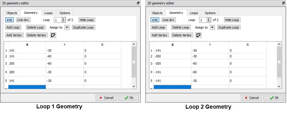
Loops in Geometry
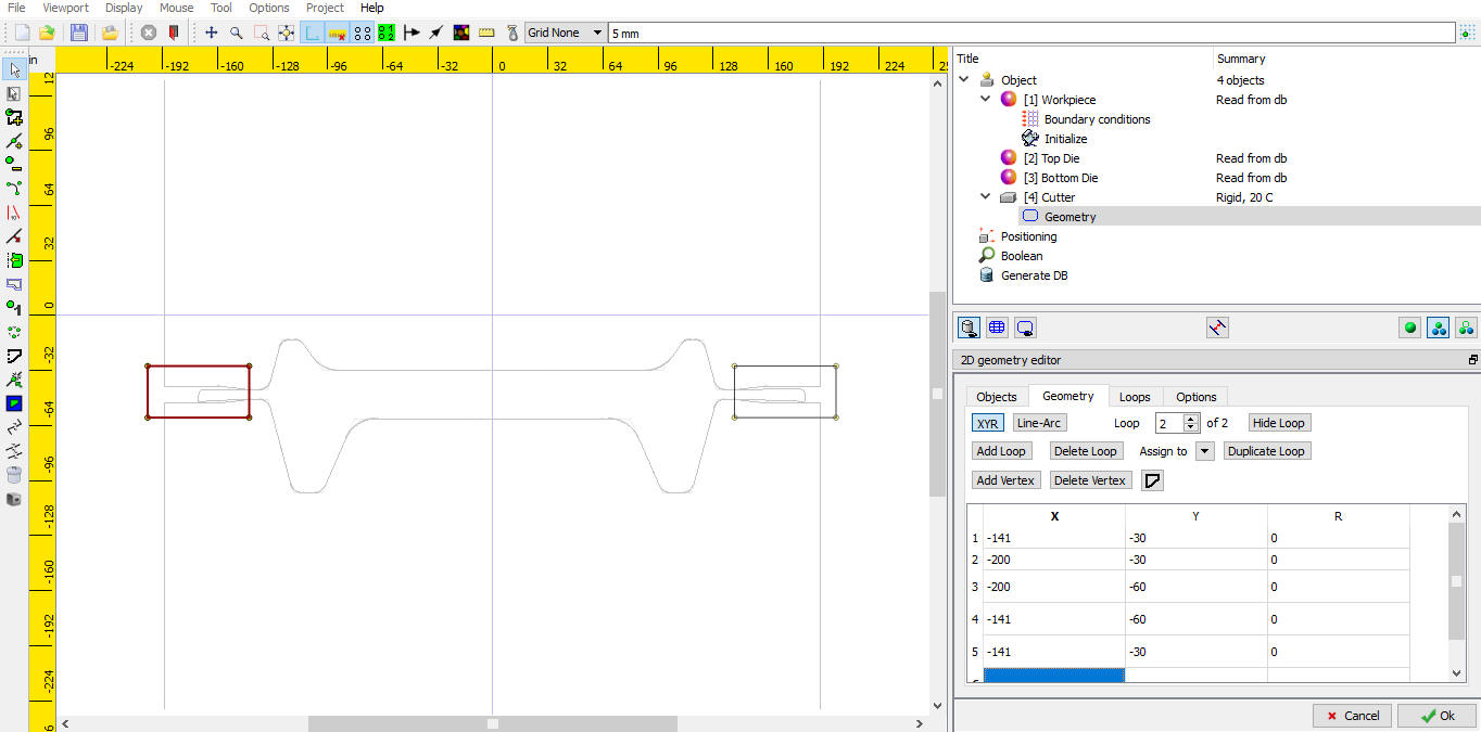
Defining Boolean geometry
Generating Database
Click on ![]() button to generate the database. After generating Database switch to Post by clicking on
button to generate the database. After generating Database switch to Post by clicking on ![]() button.
button.
Now go to Boolean operation step and observe the Workpiece. User can also verify the state variables interpolated onto the new mesh of the workpiece after boolean operation.
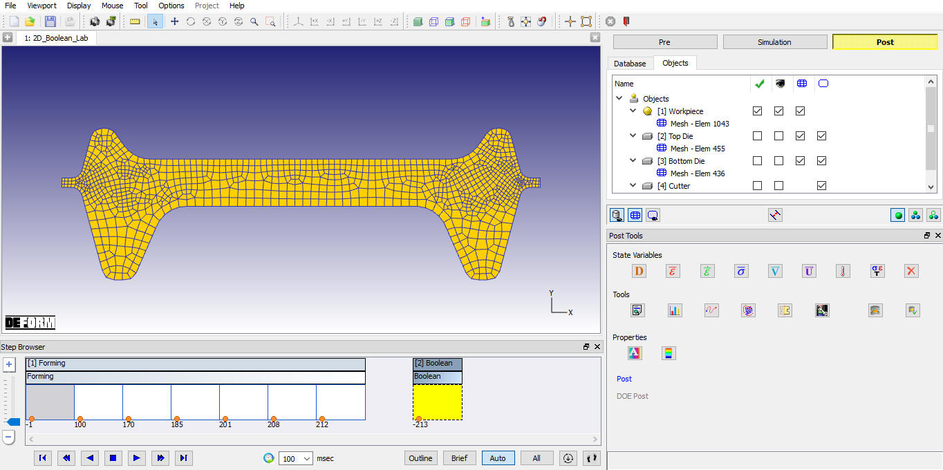
Workpiece after Boolean operation
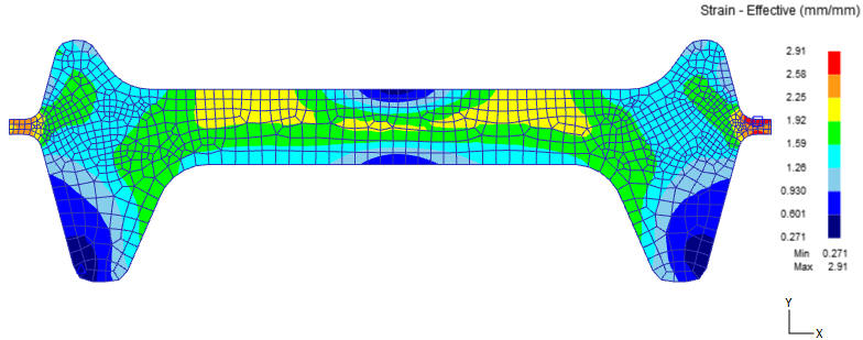
Workpiece Strain distribution after Boolean operation
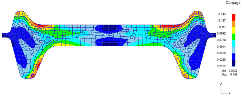
Workpiece Damage distribution after Boolean operation