RVE Lab2 : RVE model for fracture of Hard inclusion
2.1. Introduction to RVE model
2.2. Launch RVE model in Material suite
2.3. Object selection and point selection
2.4. Setting up RVE model
2.4.1. Defining RVE Model dimension
2.4.2. Defining materials for RVE Model
2.4.3. Defining RVE Model
2.4.4. Generating mesh for RVE Model
2.4.5. Defining inclusion settings
2.4.6. Generating Database to simulate RVE model
2.5. Simulating RVE model
2.6. RVE model Output
Introduction to RVE model
Representative volume element (RVE) models at micro-scale via point tracking of a given database. Using RVE model, we can study detailed micro level response (local stress and strain, defects/matrix interaction, void closure), evaluation of microstructure (particle size, volume fraction, shape orientation etc), evaluation of textures, etc.
In this lab, we will demonstrate how to use RVE to model fracture of hard inclusion.
Launch RVE model in Material suite
On a Windows machine, go to the ![]() button, select DEFORM-v1x.xxx (.xxx indicates version number E.g. v14.0.2 and select DEFORM GUI Main v1x.xx from the menu. The DEFORM GUI Main window will appear.
button, select DEFORM-v1x.xxx (.xxx indicates version number E.g. v14.0.2 and select DEFORM GUI Main v1x.xx from the menu. The DEFORM GUI Main window will appear.
We require a nominal DB to perform RVE model in material suite, for this lab we will use Forging_2D_Uniform.key from \2D\LABS\RVE_LABS folder to generate nominal DB. Open NG Pre (![]() ) to create a new problem either by selecting File
) to create a new problem either by selecting File![]() New Problem or by clicking the New Problem
New Problem or by clicking the New Problem ![]() icon as shown in Fig. RVEL2.1. Define problem Name as “Forging_2D_Uniform “ and “SystemInternational(SI) “ unit System radio button in New Problem window as shown in Fig. RVEL2.1. Click on
icon as shown in Fig. RVEL2.1. Define problem Name as “Forging_2D_Uniform “ and “SystemInternational(SI) “ unit System radio button in New Problem window as shown in Fig. RVEL2.1. Click on ![]() button.
button.
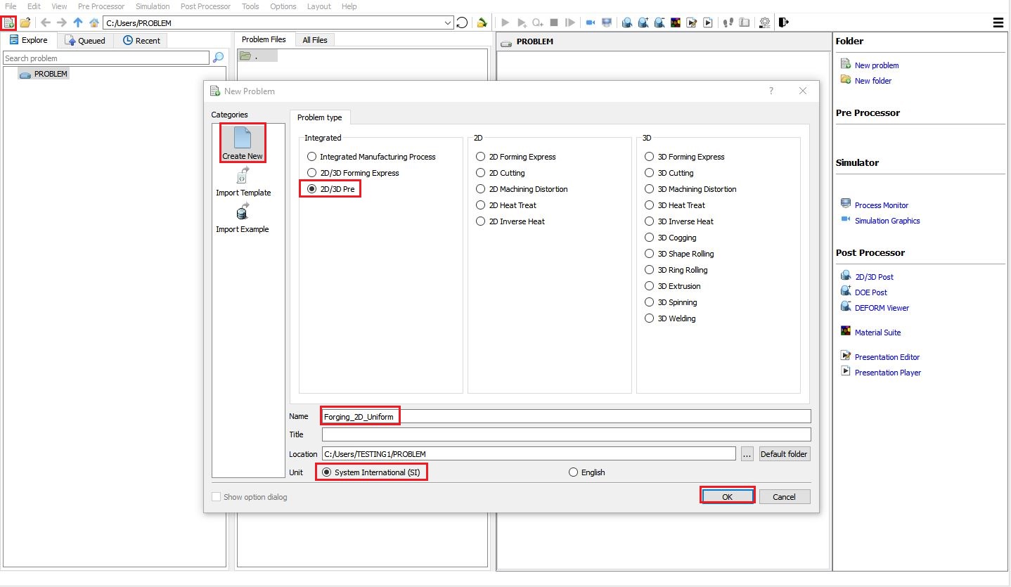
Creating New problem
NG Pre New problem window
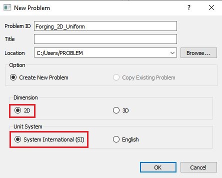
NG Pre GUI will open, keep Problem ID as “Forging_2D_Uniform “ button and “System International (SI) “ unit System , select “2D “ Dimension radio button in New Problem window as shown in Fig. RVEL2.2. Click on ![]() button to close the New Problem dialog. Import “Forging_2D_Uniform.ke y” from “\2D\LABS\RVE_LABS ” folder using “Import Keyfile ” from File menu in NG Pre as shown in Fig. RVEL2.3.
button to close the New Problem dialog. Import “Forging_2D_Uniform.ke y” from “\2D\LABS\RVE_LABS ” folder using “Import Keyfile ” from File menu in NG Pre as shown in Fig. RVEL2.3.
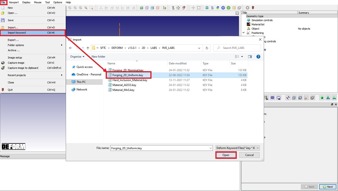
Importing Forging_2D_Uniform keyfile using Import Keyfile option
Navigate to Generate DB page and click on ![]() to generate database. Close the NG Pre and run the simulation from GUI Main, make sure simulation stops normally without any issue. Now from GUI Main, without selecting Forging_2D_Uniform.DB file click on MaterialSuite under “Post Processor” to open Material Suite module as shown in Fig. RVEL2.4.
to generate database. Close the NG Pre and run the simulation from GUI Main, make sure simulation stops normally without any issue. Now from GUI Main, without selecting Forging_2D_Uniform.DB file click on MaterialSuite under “Post Processor” to open Material Suite module as shown in Fig. RVEL2.4.
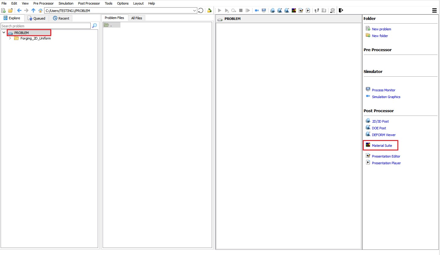
Opening Material Suite from GUI Main
After the main window for material suite is opened, click “Open…” icon (![]() ) in the top tool bar to import the database simulated above (Forging_2D_Uniform.DB). The default task item “DEFORM “ is added to the task tree. Expand “Microstructure “ item and click on “RVE Model “ icon from Microstructure list as shown in Fig. RVEL2.5., the new task item “RVE model” is added to the task tree.
) in the top tool bar to import the database simulated above (Forging_2D_Uniform.DB). The default task item “DEFORM “ is added to the task tree. Expand “Microstructure “ item and click on “RVE Model “ icon from Microstructure list as shown in Fig. RVEL2.5., the new task item “RVE model” is added to the task tree.
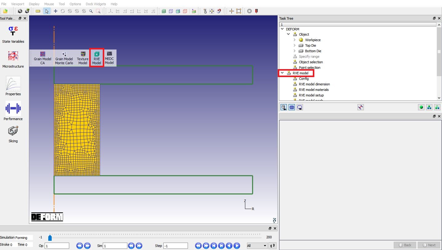
Launching RVE model in material suite
Object selection and point selection
In the “DEFORM” task tree, click on “Object selection “ item and select “workpiece “ (see Fig. RVEL2.6.). Click on “Pointselection “ item, since we are at first step when DB was loaded, the step number will be “-1” in step number field ( Fig. RVEL2.7.). Define one point on Workpiece as shown in Fig. RVEL2.7. The coordinate of point1 (P1) is (61.6289, 129.55, 0, 1). Users can choose any step number convenient for them.
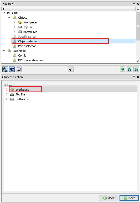
Selecting object to be used to model RVE
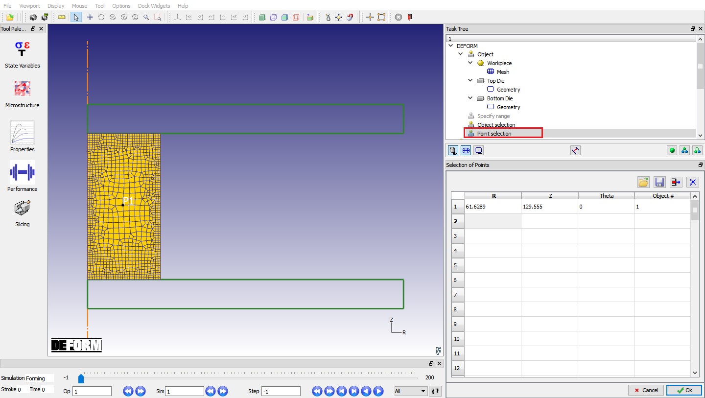
Point selection on Workpiece
Setting up RVE model
Click on “Config “ item from RVE Model Task tree, Configuration window appears. We need to specify the executable for FEM simulation and the working directory using the ![]() button adjacent to the field. The default executable for RVE model simulation is “DEF_SIMULATION.EXE”, which is in installation directory of DEFORM software. The directory containing nominal database is set as Working directory as shown in Fig. RVEL2.8.
button adjacent to the field. The default executable for RVE model simulation is “DEF_SIMULATION.EXE”, which is in installation directory of DEFORM software. The directory containing nominal database is set as Working directory as shown in Fig. RVEL2.8.
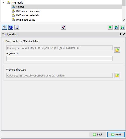
RVE Model Configuration settings
Defining RVE Model dimension
Click on “RVE model dimension ” item under RVE model Task Tree, select RVE model dimension as “2D ” as shown in Fig. RVEL2.9. Using “Import Project ” option, we can import previously saved RVE model project and using “Save Project ” option, we can save the RVE model project.
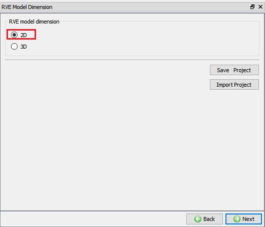
Selecting RVE model dimension
Defining materials for RVE Model
Click on “RVE model Materials “ item under RVE model Task Tree, the first material listed in the list is the material of Workpiece in the nominal database. In this lab, we will be importing one inclusion material, click on ![]() (Add button), one “New material” will be added to the list, select the “New material” in list and import “ Hard_Inclusion_Material.key “ from “2D\LABS\RVE_LABS” folder using Import
(Add button), one “New material” will be added to the list, select the “New material” in list and import “ Hard_Inclusion_Material.key “ from “2D\LABS\RVE_LABS” folder using Import ![]() option. In Matrix material (Steel) flow stress model from nominal DB is
option. In Matrix material (Steel) flow stress model from nominal DB is 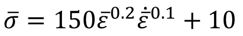 and imported Hard inclusion material flow stress model is
 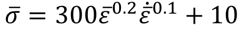 . After loading the materials, RVE Model Materials page looks like as shown in Fig. RVEL2.10. We can also import the material data from library using
 ![]() button, save the material using
button, save the material using ![]() button and we can also Edit the material using
button and we can also Edit the material using ![]() button.
button.
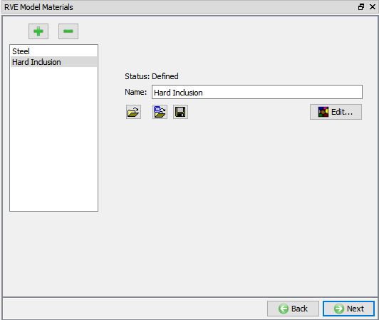
Loading material required for RVE Model
Defining RVE Model
Click on “RVE model setup “ item under RVE model Task Tree, here we can create RVE model geometry using primitive option (2D circular inner void, 2D ellipse inner void and 2D semi-ellipse surface void) or using 2D user defined RVE model option.
Under 2D user defined RVE model option, we can import geometry for Matrix and for Substructure as geometry file or keyfile using “Import user integrated RVE model from a file” button.
Under Substructure, we have following options:
-
Import geometry file button - to import Substructure geometry from a file.
-
Translation - Translates the selected geometry to the translation coordinates.
-
Rotation – Rotates the selected geometry based on defined rotation axis and Rotation angle (Degrees) data.
-
Scale - Scales the selected geometry based on scaling factor in X and Y direction.
-
Duplicate - We can duplicate the selected geometry and position the duplicated geometry based on the translation.
-
Delete - Deletes the selected geometry in list.
-
Submodel - We can define the RVE fracture plane data for the selected geometry and generate tessellation inside the selected geometry. This option will not be active for voids.
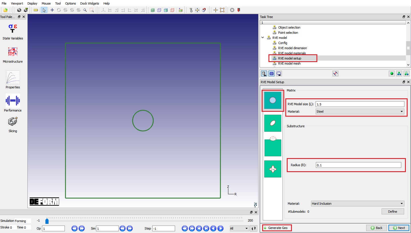
In this lab, we are creating three substructures using Submodels option. In “RVEmodel setup “ page, select “2Dcircularinnervoid ”, specify RVEmodelsize (L) as 1.5 andRadius(R) as 0.1 this will be geometry of the central substructure. Click on ![]() button, created RVE model will look like as shown in Fig. RVEL2.11.
button, created RVE model will look like as shown in Fig. RVEL2.11.
RVE model geometry
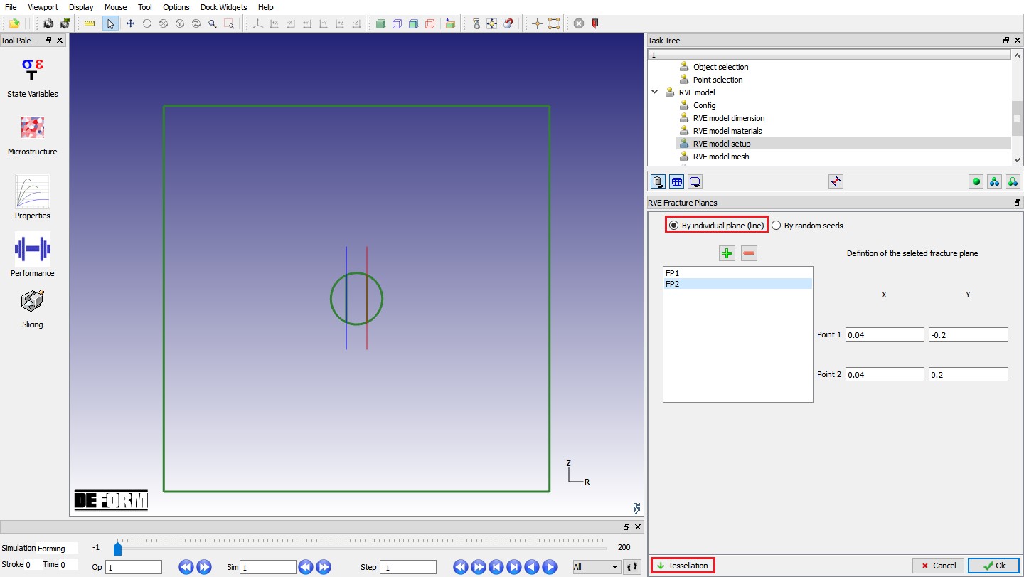
To create submodels, select Substructure Material as “Hardinclusion ” using pulldown menu as shown in Fig. RVEL2.11. and click on ![]() button, RVE Fracture Planes definition window will open. In RVE Fracture Planes, we have two options to create substructures,
button, RVE Fracture Planes definition window will open. In RVE Fracture Planes, we have two options to create substructures,
-
By individual plane (line) : using this this option we can split the substructure into sub model using defined individual plane data.
-
By random seeds : using this this option we can create sub model as per defined seeds # data.
After defining plane data when user clicks on ![]() button, substructure geometry will be created.
button, substructure geometry will be created.
In this lab, we will use “By individual plane(line) ” option to create submodels. Select “By individual plane(line) ” radio button, click on ![]() (Add) button twice to add two planes. For FP1 , define Point 1 as -0.04 (X), -0.2 (Y) and Point 2 as -0.04 (X), 0.2 (Y). Similarly, define Point 1 as 0.04 (X), -0.2 (Y) and Point 2 as 0.04 (X), 0.2 (Y) for FP2 and click on
(Add) button twice to add two planes. For FP1 , define Point 1 as -0.04 (X), -0.2 (Y) and Point 2 as -0.04 (X), 0.2 (Y). Similarly, define Point 1 as 0.04 (X), -0.2 (Y) and Point 2 as 0.04 (X), 0.2 (Y) for FP2 and click on ![]() to create Submodels. Created submodels will be as shown in Fig. RVEL2.12. Click on
to create Submodels. Created submodels will be as shown in Fig. RVEL2.12. Click on ![]() to close RVE Fracture Planes page.
to close RVE Fracture Planes page.
Creating RVE Substructure geometry
Generating mesh for RVE Model
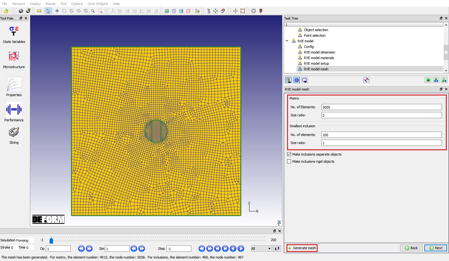
Click on “RVE model mesh “ item under RVE model Task Tree, we will consider the substructures as separate objects, hence turn on “Make inclusions separate objects “ check box. For Matrix , defineNo. of elements as 5000 and sizeratio as2 and for smallestinclusion , define No. of elements as 100 and size ratio as 1. Click on ![]() to generate mesh, generated mesh for RVE model looks like as shown in Fig. RVEL2.13.
to generate mesh, generated mesh for RVE model looks like as shown in Fig. RVEL2.13.
Mesh settings for RVE model inclusions
Defining inclusion settings
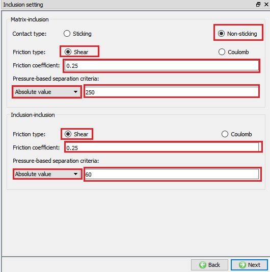
Click on “Inclusion settings “ item under RVE model Task Tree. In Matrix-inclusion contact relation, select contact type as “Non sticking “ and friction type as “Shear “ with friction coefficient of0.25 , then select Pressure-based separation criteria as “Absolutevalue ” and define Absolute value as250 as shown in Fig. RVEL2.14. Similarly, In Inclusion-inclusion contact relation, select friction type as “Shear “ with friction coefficient of 0.25 , select Pressure-based separation criteria as “Absolutevalue ” and define Absolute value as 60 as shown in Fig. RVEL2.14.
Defining Inclusion settings
Generating Database to simulate RVE model
Click on “RVE model DB generation “ item under RVE model Task Tree, we can observe the RVE model setup information in RVE model DB generation page. Click on ![]() button to generate Database to simulate the RVE model. After generating Database successfully, we can observe “Database files are generated successfully for all tracked points!” message in Status bar (See Fig. RVEL2.15.)
button to generate Database to simulate the RVE model. After generating Database successfully, we can observe “Database files are generated successfully for all tracked points!” message in Status bar (See Fig. RVEL2.15.)
After generating database, we can observe that RVE_MODEL folder is created under working directory. Inside RVE_MODEL directory, separate directories for each point will be created with “Point *” containing RVE model database along with .txt files of point tracking data for stress components, mean temperature and Velocity gradient state variables.
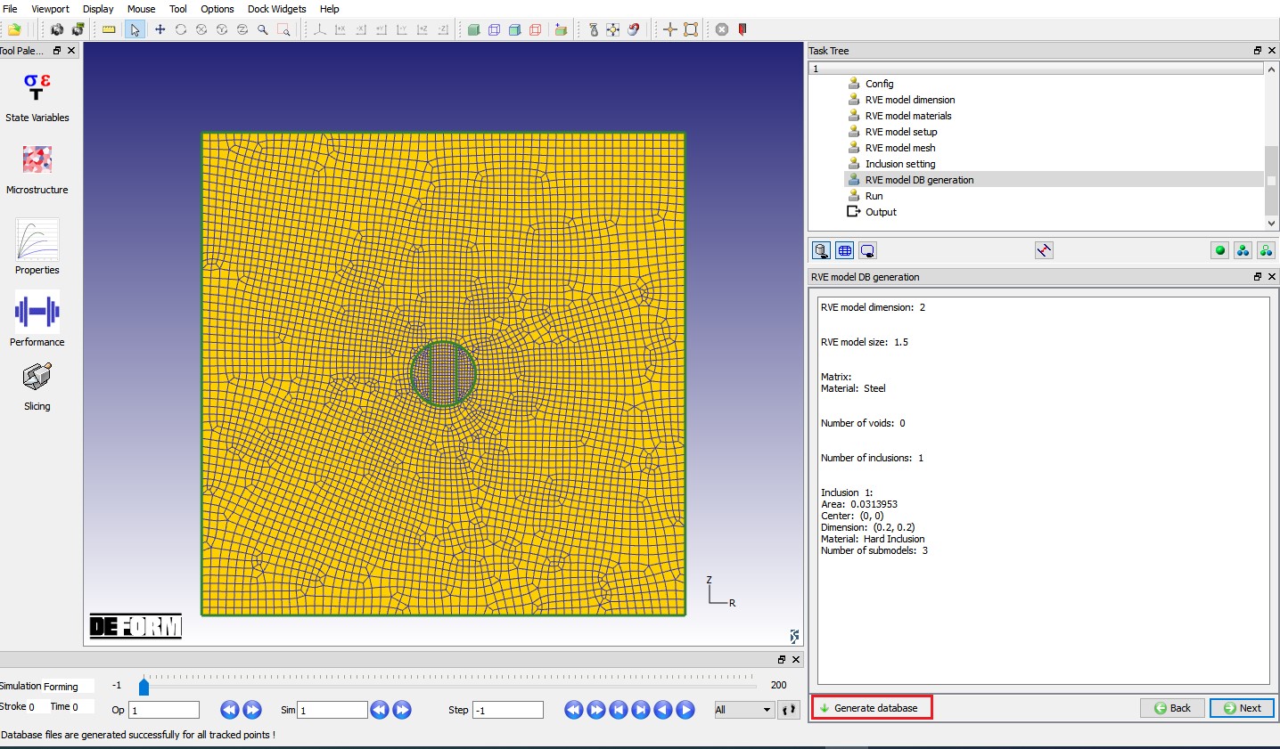
Database generation page for RVE model
Simulating RVE model
Click on “Run “ item in the task tree and click on “Compute “ button in the data window to run the simulation (see Fig. RVEL2.16.).
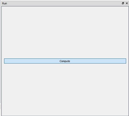
RVE model Run page
RVE model Output
After completion of simulation, click on “Point1 “ item under “Output ” in task tree, go to last step and plot Strain Effective state variable (see Fig. RVEL2.17.). We can play the animation to observe the material fracture behavior during forming operation. Fig. RVEL2.18. shows the fracture of submodels at different steps.
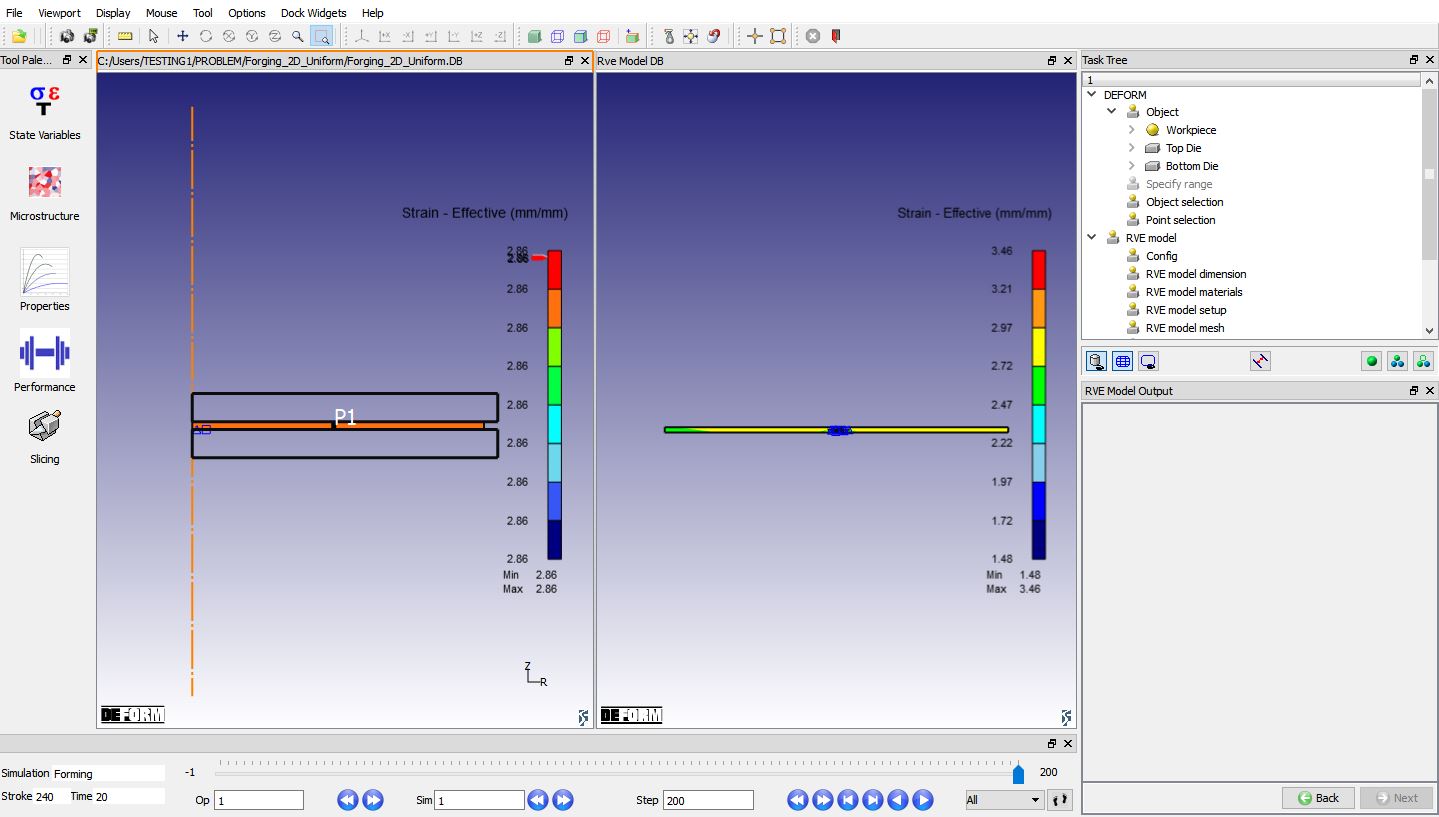
Point1 Output at last step with Effective Strain state variable
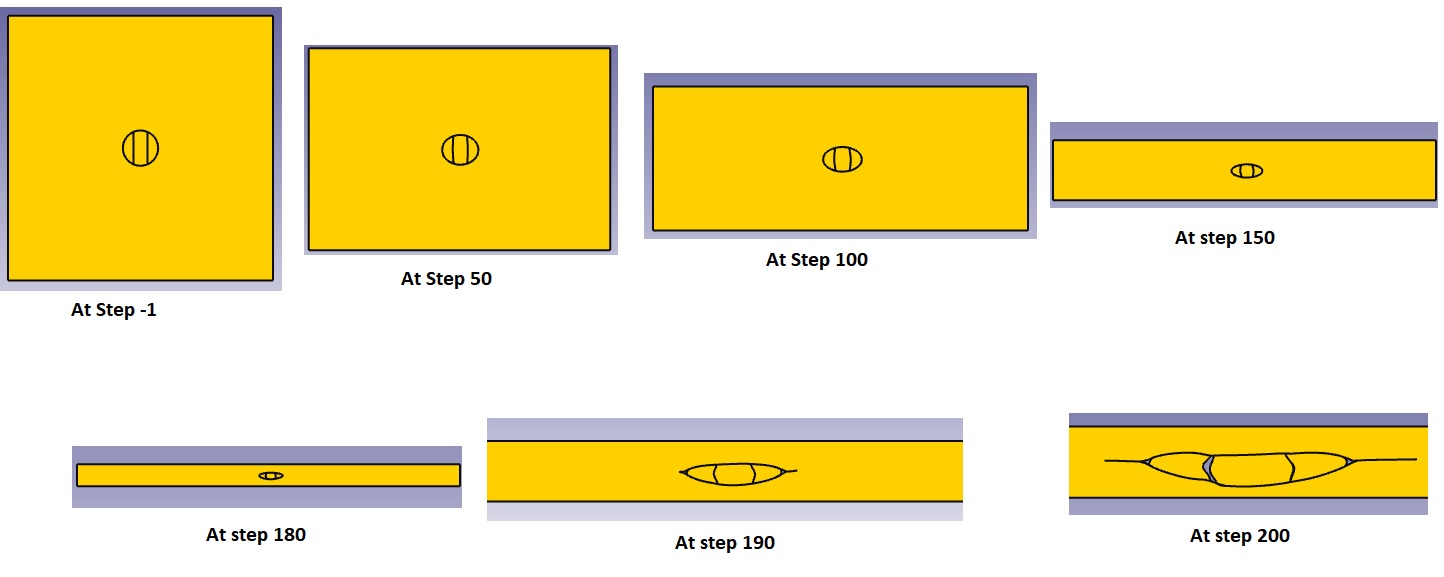
Point1 Fracture with Hard inclusion at different steps