3D Drilling Lab
1.1. Summary
1.2. Starting the 3D machining wizard
1.3. Define Machining Process data
1.4. Defining Drill bit
1.4.1. Drill bit object definition
1.4.2. Defining drill bit geometry
1.4.3. Assigning the tool material
1.4.4. Generating mesh for Tool
1.4.5. Defining BCC for Tool
1.5. Defining Workpiece
1.5.1. Workpiece object definition
1.5.2. Defining geometry for Workpiece
1.5.3. Defining Workpiece material
1.5.4. Workpiece Mesh Generation
1.5.5. Defining BCC for Workpiece
1.6. Positioning the objects
1.7. Defining tool wear parameters
1.8. Defining inter-object relations
1.9. Defining step controls
1.10. Generating database
1.11.Running Simulation
1.12. Post Processing simulation results
Summary
In this lab, we will demonstrate how to setup drilling lab using 3D Cutting wizard. Drilling simulations in DEFORM are time consuming due to the number of revolutions of a drill necessary to establish characteristic behaviour. Therefore, every effort will be made to optimize problem size. Considerations include keeping the workpiece as small as possible while capturing geometry (both in diameter and thickness), using the largest element which can adequately capture chip geometry, and possibly pre-shaping the workpiece to eliminate the necessity to simulate the transient point penetration before the drill reaches full depth. This tutorial will use the example of a 6mm two flute twist drill running at 400RPM with a 0.15mm/rev feed.
Starting the 3D machining wizard
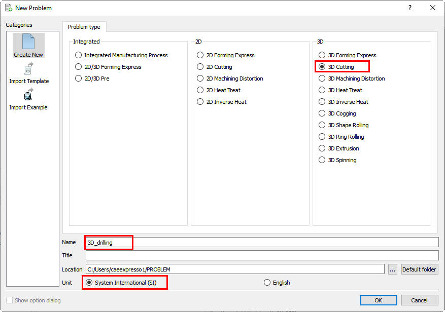
Create a new problem either by selecting File![]() **New Problem** or by clicking the New Problem
**New Problem** or by clicking the New Problem ![]() icon. The Problem Setup window will appear as shown in Fig. 3DDL1.1.) Select “ 3D Cutting “ radio button and Unit system as “SI “ (See Fig. 3DDL1.1.). Define Problem Name as “3D_drilling “ and click on
icon. The Problem Setup window will appear as shown in Fig. 3DDL1.1.) Select “ 3D Cutting “ radio button and Unit system as “SI “ (See Fig. 3DDL1.1.). Define Problem Name as “3D_drilling “ and click on ![]() button to open a new Problem with 3D Cutting operation in MO wizard.
button to open a new Problem with 3D Cutting operation in MO wizard.
Creating new Machining operation
Define Machining Process data
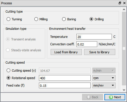
In the ‘Process’ page, select Cutting type as ‘Drilling ‘, enter the Environment temperature as 20 °C and use default Convection coefficient as 0.02 N/sec/mm/C. Define Rotational speed as 400 rpm and feed rate (f) as 0.15 mm/rev as shown in the Fig. 3DDL1.2. Click ![]() until Tool page.
until Tool page.
Setting up process parameters for Drilling operation
Defining Drill bit
Drill bit object definition
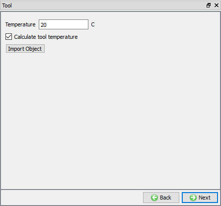
In this Tool page, Define the temperature as 20 °C and turn on the “Calculatetool temperature ” check box so that we can mesh the tool to calculate temperature distribution as shown in the Fig. 3DDL1.3. Click ![]() to Tool geometry page.
to Tool geometry page.
Tool object page
Defining drill bit geometry
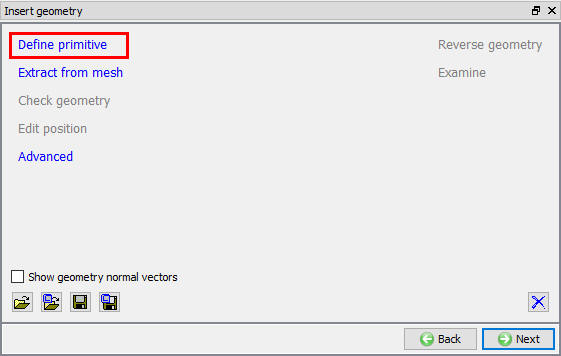
In this Insert Geometry page, the user needs to define the tool geometry using the Define primitive link. Using the ![]() link as shown in the Fig. 3DDL1.4., we will be opening ‘Drillbit Primitive’ window as shown in the Fig. 3DDL1.5. click on
link as shown in the Fig. 3DDL1.4., we will be opening ‘Drillbit Primitive’ window as shown in the Fig. 3DDL1.5. click on ![]() button to create drill bit geometry using the parameters as shown in the Fig. 3DDL1.5.
button to create drill bit geometry using the parameters as shown in the Fig. 3DDL1.5.
Tool geometry page
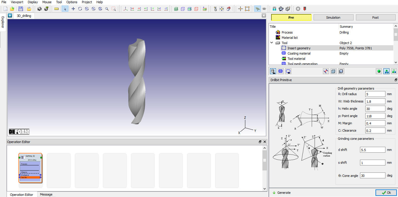
Defining drill bit geometry
Assigning the tool material
In Material Window, we need to load the material from the library. So, click on “Load form Library” option ![]() and select hot formingdie material category and select ‘Carbide(15%Cobalt) ‘ material from the list to assign the material for tool as shown in the Fig. 3DDL1.6. Click
and select hot formingdie material category and select ‘Carbide(15%Cobalt) ‘ material from the list to assign the material for tool as shown in the Fig. 3DDL1.6. Click ![]() to generate mesh for tool.
to generate mesh for tool.
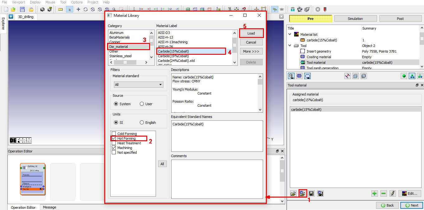
Assigning the Tool Material
Generating mesh for Tool
In Tool mesh page, select the UseRelative mesh size method. Define target number of elements as 20000 and size ratio as 0.3 as shown in the Fig. 3DDL1.7. Click on ![]() to generate mesh. Mesh looks like as shown in Fig. 3DDL1.7. Click
to generate mesh. Mesh looks like as shown in Fig. 3DDL1.7. Click ![]() to BCC page.
to BCC page.
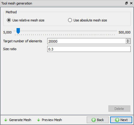
Tool Mesh Generation using relative mesh size
Defining BCC for Tool
In this BCC Page, the user can define Thermal BCCs “HeatExchange withEnvironment ” and “Temperature ”. The default BCC is assigned to the entre outer surface of the drill bit automatically after generating the mesh as shown in the Fig. 3DDL1.8.
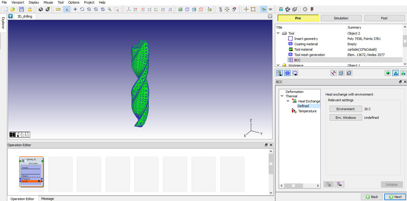
Heat exchange BCC over Tool
Defining Workpiece
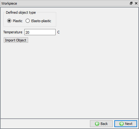
Workpiece object definition
In this Workpiece object page, define the temperature as 20 °C and object type as plastic as shown in the Fig. 3DDL1.9. Click ![]() to workpiece geometry page.
to workpiece geometry page.
Workpiece object Page
Defining geometry for Workpiece
In this Workpiece Geometry page, we need to define the workpiece geometry using the ![]() . In workpiece geometry primitive page, select the cylinder radio button and defineDiameter(D) as 12mm , Thickness as 4mm and Drilltip depth as 3.15mm as shown in the Fig. 3DDL1.10.
. In workpiece geometry primitive page, select the cylinder radio button and defineDiameter(D) as 12mm , Thickness as 4mm and Drilltip depth as 3.15mm as shown in the Fig. 3DDL1.10.
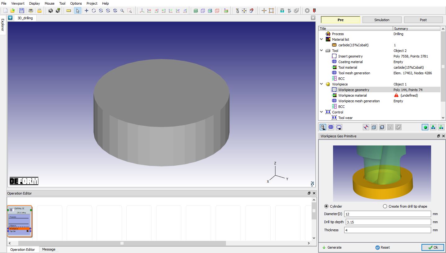
Creating the cylinder workpiece geometry
Defining Workpiece material
In Material Window, we need to load the material from the library. So, click on “LoadformLibrary ” option ![]() and select AISI-1045(Machining) from the Steel category to assign the material for workpiece as shown in the Fig. 3DDL1.11. Click
and select AISI-1045(Machining) from the Steel category to assign the material for workpiece as shown in the Fig. 3DDL1.11. Click ![]() to generate mesh for workpiece.
to generate mesh for workpiece.
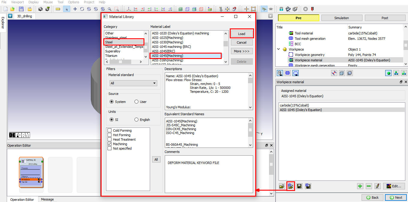
Assigning the material for the workpiece
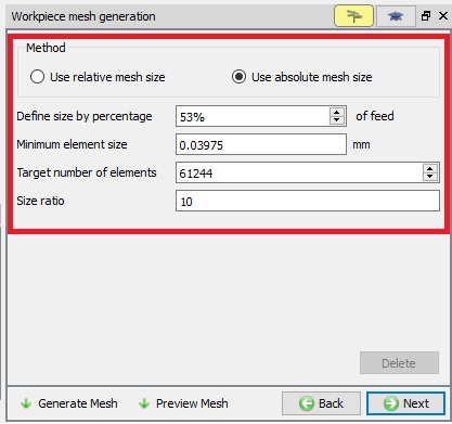
Workpiece Mesh Generation
After the work piece geometry is generated, in mesh page, using the absolute mesh size method define element size ratio as 10 , and Minimum element size as 0.04 mm as shown in Fig. 3DDL1.12. Click on ![]() to complete mesh generation for the Workpiece.
to complete mesh generation for the Workpiece.
Runtime meshing parameters:
To set runtime meshing parameters, switch to expert mode using ![]() . In expert mode selectweighting factors tab and define Strain weight to about 0.65 , StrainRate weight to about 0.35 and make other weights to zero (Including mesh windows) as runtime mesh parameters (See the Fig. 3DDL1.13.). After setting weighing factors, switch to guided mode using
. In expert mode selectweighting factors tab and define Strain weight to about 0.65 , StrainRate weight to about 0.35 and make other weights to zero (Including mesh windows) as runtime mesh parameters (See the Fig. 3DDL1.13.). After setting weighing factors, switch to guided mode using ![]() . Click
. Click ![]() to BCC page.
to BCC page.
Workpiece mesh generation using absolute mesh size
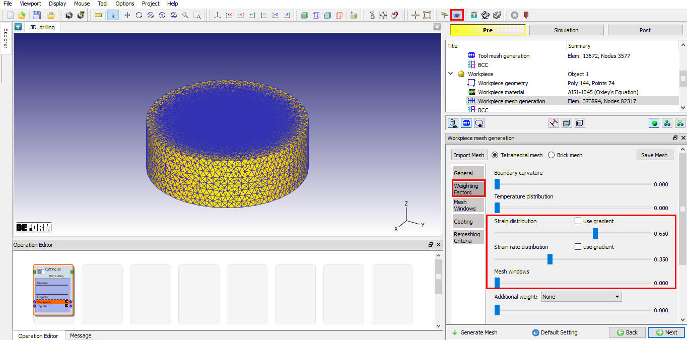
Runtime Workpiece mesh generation weighting factor parameters
Defining BCC for Workpiece
In BCC Page, by default the velocity of all nodes on the circumference of the workpiece are fixed in X, Y and Z directions as shown in the Fig. 3DDL1.14. Heat exchange boundary conditions are assigned to top and bottom surfaces automatically during mesh generation as shown in the Fig. 3DDL1.15. Click ![]() to Control page.
to Control page.
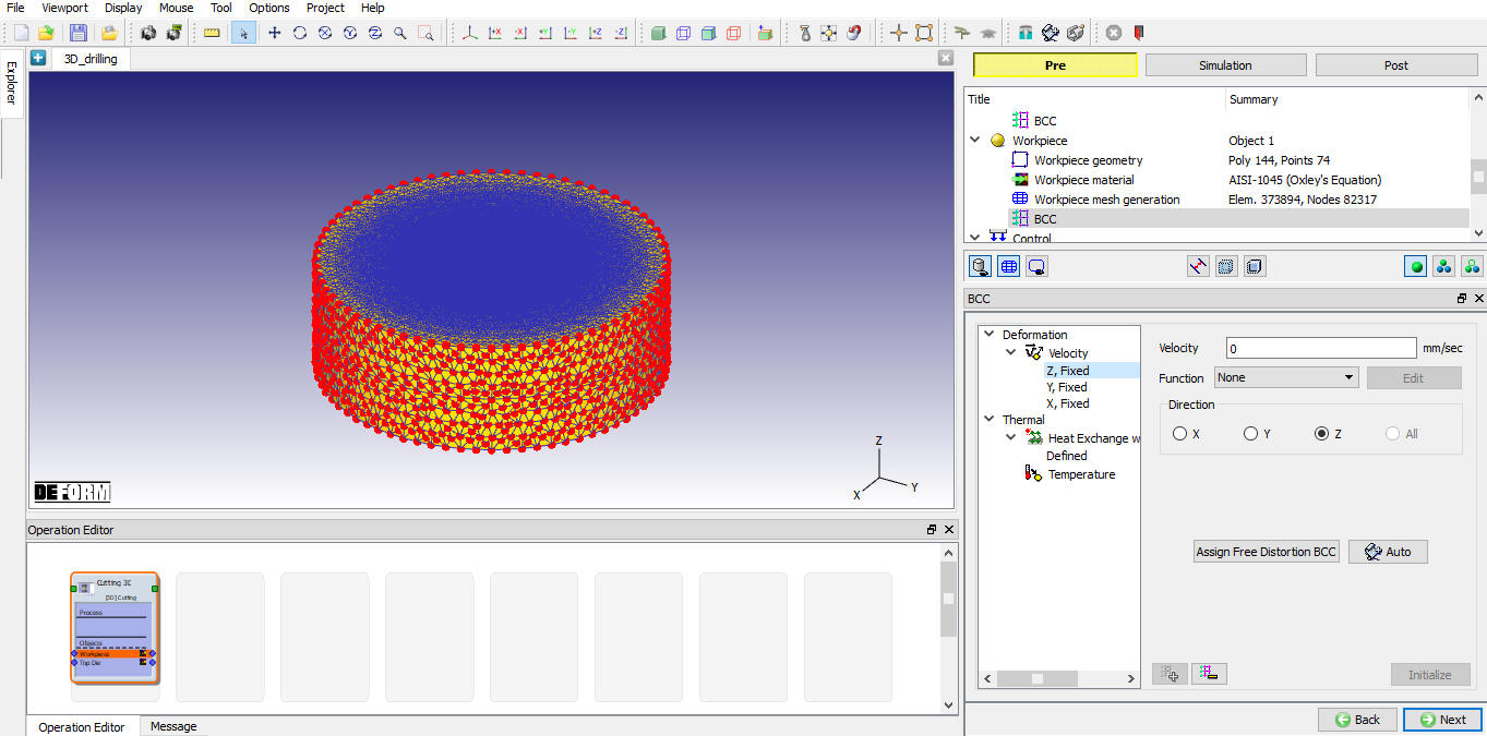
Defining the velocity BCC data
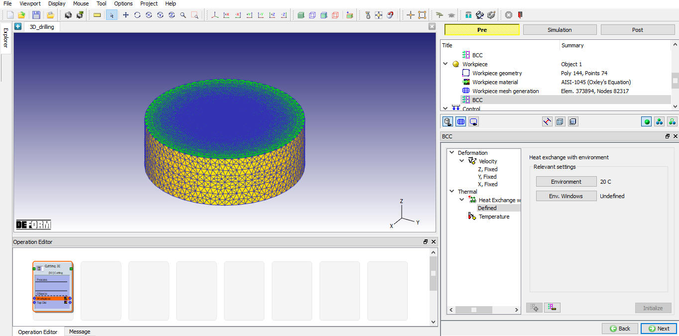
Defining Heat Exchange BCC
Positioning the objects
In Control page, click on ‘Position objects’ and check the position of Tool. If the Tool is not in contact with Workpiece, position the tool using interference method and click ![]() to define tool wear parameters.
to define tool wear parameters.
Defining tool wear parameters
In Tool wear page, turn on the “Definemodel to calculate tool wea r” check box and select Usui model, use the default parameters for Usui model as shown in the Fig. 3DDL1.16. Click ![]() to Contact page.
to Contact page.
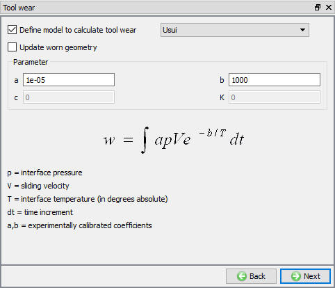
Defining Tool Wear parameters
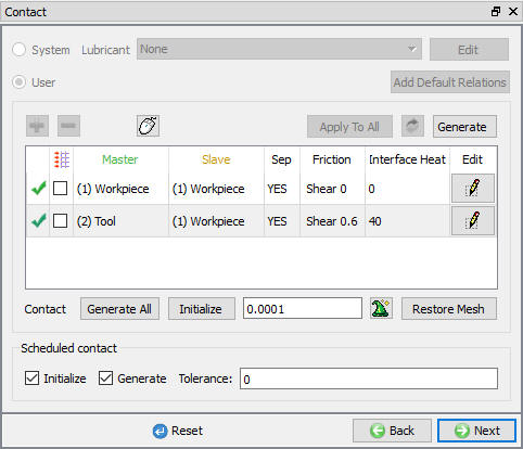
Defining inter-object relations
In Contact page, we will use default relations. Click on Tool - Workpiece relation Edit button and define shear friction factor as 0.6 and the interface heat transfer coefficient as 40 N/sec/mm/C (as shown in Fig. 3DDL1.17.), click on ![]() to generate contacts. Click
to generate contacts. Click ![]() to Step Control page.
to Step Control page.
Contact page
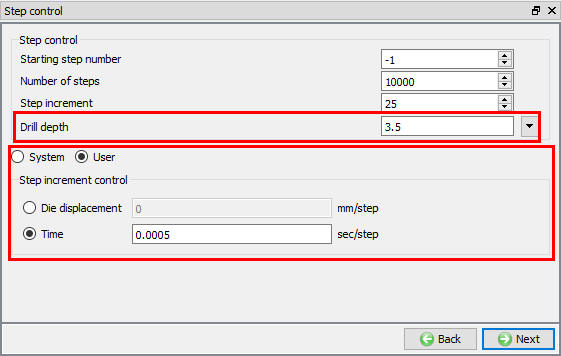
Defining step controls
In Step control page, define the drill depth as 3.5mm and select User radio button to set user definedtime step increment as 0.0005 , keep the rest of the values to default as shown in the Fig. 3DDL1.18. and proceed to generate the database by clicking ![]() .
.
Step controls page in GUIDED Mode
Generating database
In Generate database page, click on the ![]() button to generate the database. Observe messages in Message tab informing database generation status. If there are any errors, we need to correct them before generating Database
button to generate the database. Observe messages in Message tab informing database generation status. If there are any errors, we need to correct them before generating Database
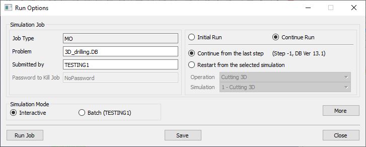
Running Simulation
Once the database has been generated switch to the Simulation mode by clicking on ![]() button above the operation tree. Click on the
button above the operation tree. Click on the ![]() action label to open the Run Options dialog as shown in Fig. 3DDL1.19. Use the default ContinueRun option to select “Continue from the last step ” (from step -1) option and then select the Simulation mode as Interactive radio button. Click on
action label to open the Run Options dialog as shown in Fig. 3DDL1.19. Use the default ContinueRun option to select “Continue from the last step ” (from step -1) option and then select the Simulation mode as Interactive radio button. Click on ![]() button to run the simulation.
button to run the simulation.
To define MPI settings, click on ![]() button, Run Options window will expand and displays options to define MPI settings for simulation (max number of processors that can be defined depend on your 3D MPI license).
button, Run Options window will expand and displays options to define MPI settings for simulation (max number of processors that can be defined depend on your 3D MPI license).
Run Simulation Window
Monitor the progress of the simulation by looking at the Simulation Message and Simulation Log tab, making sure that ![]() option is checked. User can view the drilling process as the simulation proceeds to the specified drill depth from Simulation graphics.
option is checked. User can view the drilling process as the simulation proceeds to the specified drill depth from Simulation graphics.
Post Processing simulation results
When the simulation is completed, review the results by switching to Post mode using the ![]() button above the Simulation tool bar. Play through the steps of the simulation and observe the chip formation during drilling process.
button above the Simulation tool bar. Play through the steps of the simulation and observe the chip formation during drilling process.