15.3. Hammer
15.3.1. Anvil Type Hammer
15.3.2. Counterblow Hammer
[2D, 3D] : Hammer forging operation is controlled by energy. During a working stroke, the deformation proceeds until the total kinetic energy is dissipated by plastic deformation of the material and by elastic deformation of ram and anvil when the die and ram faces contact each other. (See Fig. 15.3.1. and Fig. 15.3.2.)
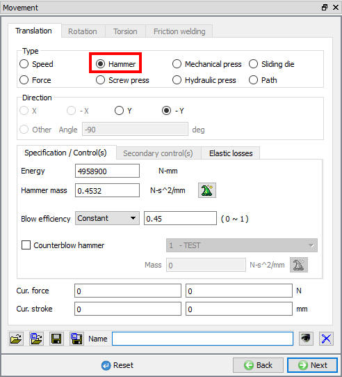
2D Hammer Press movement controls window

3D Hammer Press movement controls window
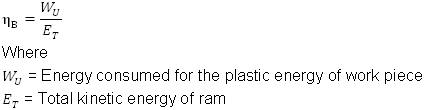
During hammer forging operation, only a portion of the kinetic energy of ram is used for the plastic deformation of work piece. The rest of the energy is lost through anvil and machine frame.
The blow efficiency  is defined by:
 |
|
—|—
These values can be set in the movement controls window.
There are basically two types of hammer. The first is an anvil type hammer and the other counter blow hammer. The formulations and assumptions used for the two types of hammer forging operations are given below:
Anvil Type Hammer [2D, 3D]
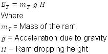
In an anvil type hammer, the workpiece, together with the lower die set, is placed on an anvil which is stationary. In a simple gravity drop hammer, the ram is accelerated by gravity and accumulates energy.
Therefore the blow energy  is calculated by:
 |
|
—|—
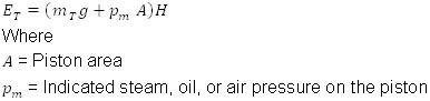
In a power drop hammer, the ram is accelerated by steam, cold or hot air pressure in addition to gravity.
The total blow energy is given by:
 |
|
—|—
The velocity of ram  is calculated by:
 |
|
—|—
The plastic deformation energy during a small time increment  is calculated by:
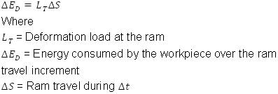 |
|
—|—
After the increment, the blow energy is adjusted by:
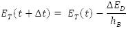 |
|
—|—
This adjustment accounts for elastic energy loss. The simulation is repeated until the blow energy becomes zero.
The characteristic values of Anvil type hammers are given in the following Table 15.3.1.
| Hammer ype | ** | E, KN-m (ft-lbf) | nB | Vs, m/sec (ft/sec) | nB, min-1 | nH |
|---|---|---|---|---|---|---|
| Free Drop Hammer | Belt | 40(29,440) | 0.3-0.6 | 4-5(13-16.4) | 40 | 0.2-0.3 |
| Board | 16(11,780) | 0.3-0.6 | 4-5(13-16.4) | 35 | 0.2-0.3 | |
| Chain | 100(73,600) | 0.3-0.6 | 4-5(13-16.4) | 55 | 0.5 | |
| Piston | 63(46,370) | 0.3-0.6 | 4-5(13-16.4) | 60 | 0.5 | |
| Power Drop Hammer | Pneumatic | 50(36,800) | 0.8-0.9 | 5-8(16.4-26.3) | 80-250 | 0.45-0.55 |
| Open-die, single frame | 40(29,440) | 0.8-0.9 | 5-8(16.4-26.3) | 450 | 0.45-0.55 | |
| Open-die, double frame | 250(184,000) | 0.8-0.9 | 5-8(16.4-26.3) | 55-240 | 0.5 | |
| Die forging | 100(73,600) | 0.3-0.6 | 5-8(16.4-26.3) | 55-240 | 0.5 |
Characteristic values of Anvil type hammers
Counterblow Hammer [2D, 3D]
A counterblow hammer is defined by specifying the counterblow hammer checkbox for one die, as shown in Fig. 15.3.3. and Fig. 15.3.4. The total energy should be defined for the first die (generally the primary die). The mass of each die should be assigned to that respective die.
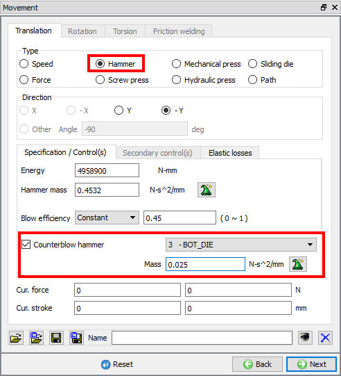
2D Counter blow hammer press settings

3D Counter blow hammer press settings
DEFORM assumes that momentum is matched between dies in counterblow hammers. That is, M1* V1 = M2* V2, where M and V are the mass and velocity of the respective dies. DEFORM will automatically split energy between the two dies and calculate the velocity of each die. The inputs are as summarized in Table 15.3.2.
| Die 1 | Die 2 | |
|---|---|---|
| Energy | Total Energy | 0 |
| Mass | Mass of Die 1 | Mass2 |
| Efficiency | Blow efficiency | Inherited from Die 1 |
| Velocity | Sqrt (2EM2/((M1+M2)*M1)) | V1*M1/M2 |
Hammer movement input summary
Related Topics: