Appendix VIII: Preventing leakage of nodes in sectioned simulations
In many cases, To prevent the leaking of nodes about symmetry planes, requires extra information so that the simulation engine knows the exact definition of the symmetric condition. This is done by two definitions:
-
The deforming body needs a symmetric plane definition on the cut surfaces.
-
The rigid geometry require a symmetric surface definition on their cut surfaces.
In the example used for this section, the spike simulation (See Fig. AVIII.1.) will be used to demonstrate this capability. Note that the die geometries and the workpiece mesh are the same size. What follows is a step-by-step procedure that shows how this simulation is constructed in order to allow the geometry and mesh to coincide in size.
Note:
If there is a difference in the size of the die versus the workpiece in the symmetry surfaces, it is safer to error in making the dies larger.
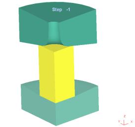
Spike problem being used as the example case
Step 1: Define symmetric surface on workpiece cut faces to allow for proper meshing.
On the workpiece geometry, the cut faces should have symmetric surface defined prior to the meshing step (See Fig. AVIII.2.). This option is available from the geometry selection under the symmetric surface tab. This information allows the mesh generator to maintain a tight seam of nodes on the centerline.
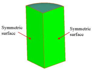
Adding symmetric surface to the part helps the part maintain the centerline during meshing
Step 2: Define symmetry surface boundary condition on cut faces of workpiece to maintain proper symmetry.
After the mesh has been generated for the workpiece, the nodes on the symmetry surfaces must be given a boundary condition to hold them in the plane. This is done under the BCC window. Use the symmetry plane selection and define symmetry planes for both cut surfaces (See Fig. AVIII.3.). After this, the workpiece boundary conditions are taken care of in terms of leakage.
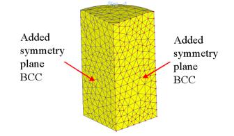
Adding symmetry planes in the boundary condition window maintains the nodes in a planar condition
Step 3: Add symmetric surface to die geometry cut surfaces.
Adding symmetric surface condition to the geometry of both the top die (See Fig. AVIII.4.) and the bottom die completes the specification that allows the dies and workpiece to be the same size.
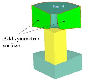
Adding a symmetric surface to the top die prevents any leakage from occurring
Related Topics: