2D Boolean and Trimming with Fracture Lab
DEFORM includes many ways of removing material:
-
Boolean
-
Shearing
-
Fracture
Boolean can be performed either as an interactive pre-processing operation, or as an operator between operations.
In this lab, a Boolean operation will be performed interactively in the preprocessor, followed by a forming operation with fracture.
1.1. Creating New problem
1.2. Adding 2D Forming Operation
1.3. Select Geometry type and Simulation Modes
1.4. Adding Objects
1.5. Loading Workpiece data
1.6. Defining Top die object data
1.6.1. Create Top Die geometry from primitive
1.7. Performing Boolean operation
1.8. Workpiece Mesh page
1.8.1. Defining Fracture data in Material
1.8.2. Assigning Workpiece Fracture properties
1.9. Defining Top die object data for Flash trimming operation
1.9.1. Import the trim punch geometry
1.9.2. Assigning movement controls to trim punch
1.10. Defining Bottom die object data
1.10.1. Import the trim die geometry
1.11. Defining Object 4 object data
1.11.1. Import the trim flash holder geometry
1.11.2. Assigning movement controls to trim flash holder
1.12. Positioning object
1.13. Define Inter-object relations
1.14. Assign Step controls
1.15. Data checking and database generation
1.16. Run and monitor a simulation
1.17. Review Results
Creating New problem
On a Windows machine, go to the ![]() button select DEFORM-v1x.xxx (.xxx indicates version number E.g. v14.0.2) and select DEFORM GUI Main v1x.x from the menu. The DEFORM GUI Main window will appear.
button select DEFORM-v1x.xxx (.xxx indicates version number E.g. v14.0.2) and select DEFORM GUI Main v1x.x from the menu. The DEFORM GUI Main window will appear.
Create a new problem either by selecting File![]() New Problem or by clicking the New Problem
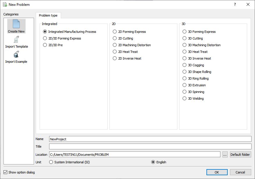
New Problem or by clicking the New Problem ![]() icon. The Problem Setup window will appear as shown in Fig. 2DBTL1.1. Select “ Integrated Manufacturing Process “ radio button and unit system as “English “ radio button in unit field. Define Problem Name as “ Boolean_Trimming “ and make sure the “Show option dialog” check box is turned on (if we do not turn on the “Show option dialog ” check box, then we will not get the New Project dialog in MO UI). Then click on
icon. The Problem Setup window will appear as shown in Fig. 2DBTL1.1. Select “ Integrated Manufacturing Process “ radio button and unit system as “English “ radio button in unit field. Define Problem Name as “ Boolean_Trimming “ and make sure the “Show option dialog” check box is turned on (if we do not turn on the “Show option dialog ” check box, then we will not get the New Project dialog in MO UI). Then click on ![]() button to open a new Problem using the Deform Integrated Manufacturing Process.
button to open a new Problem using the Deform Integrated Manufacturing Process.
Problem Setup Window
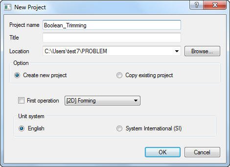
Multiple operation wizard will open with the New Project dialog, at this point user will be prompted to specify a project name (system will create a separate folder with this project name) and title for this session. In this session we will use “Boolean_Trimming “ as the project name. Confirm that First operation check box is unchecked as we will add operation later, click on ![]() to continue to open the operation.
to continue to open the operation.
New MO Project window
Adding 2D Forming Operation
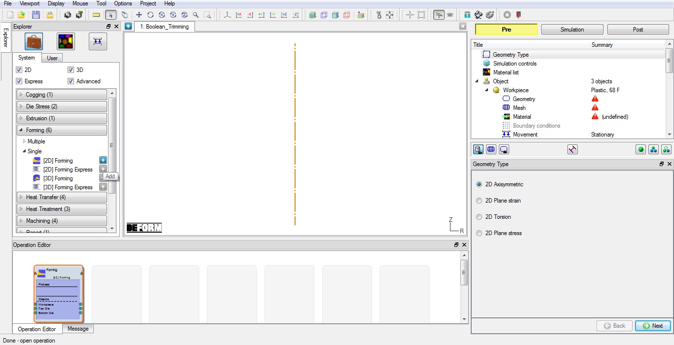
Multiple Operation wizard will open new project. Add 2D Forming operation from the Explorer Operations list. Operation can be add by clicking on 2D Forming operation ![]() button (See Fig. 2DBTL1.3.) or user can also added by drag and drop into the Operation Editor.
button (See Fig. 2DBTL1.3.) or user can also added by drag and drop into the Operation Editor.
Adding 2D Forming operation from operation explorer
Select Geometry type and Simulation Modes
Confirm the geometry type selected is Axi-symmetric in Geometry type page, then click ![]() .
.
In this lab we will be showing how to setup trimming operation with Isothermal condition, so in Simulation controls page, Check the Deformation mode check box, then click ![]() until Objects page.
until Objects page.
Adding Objects
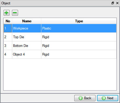
The forming operation to be simulated requires a workpiece and three dies. By default three objects will be added in Forming operation list, so add another object by clicking the ![]() (insert object) button to add 4th object in list, Workpiece and three dies. Object window looks as shown in Fig. 2DBTL1.4. Click
(insert object) button to add 4th object in list, Workpiece and three dies. Object window looks as shown in Fig. 2DBTL1.4. Click ![]() button.
button.
Adding Objects in list
Loading Workpiece data
Click the ![]() button and Import the “gear2.DB “ file from DEFORM installation folder **Tutorials** directory. Select Last step in Step List page (See Fig. 2DBTL1.5.) and Select workpiece in Object selection window. Now the loaded workpiece shape from the database should be like as shown in Fig. 2DBTL1.6. Click
button and Import the “gear2.DB “ file from DEFORM installation folder **Tutorials** directory. Select Last step in Step List page (See Fig. 2DBTL1.5.) and Select workpiece in Object selection window. Now the loaded workpiece shape from the database should be like as shown in Fig. 2DBTL1.6. Click ![]() until Top die page.
until Top die page.
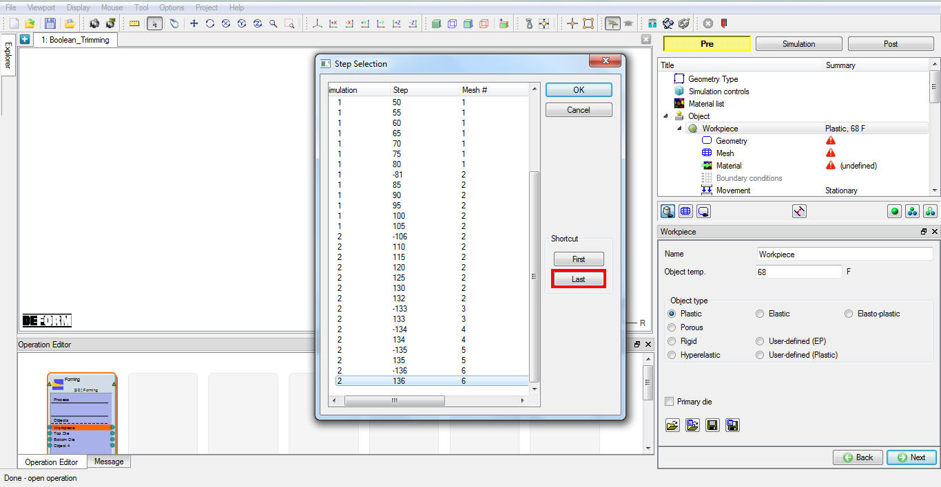
Step selection page popup window
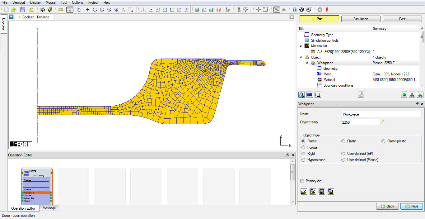
Loaded Workpiece object data from Database
Defining Top die object data
Change the Object name to “Trim Geo “, Keep the Top die default temperature as 68 ° F and confirm the object type selected as rigid and Primary die. Click ![]() to Top die geometry page.
to Top die geometry page.
Create Top Die geometry from primitive
Click on the ![]() button to create a geometry within DEFORM. The Trim Geo dia is 5.5”, and Height of 3” with Y: -1”, so you will define a width of half the diameter. Define Radius as 2.75 “ and Height(H) as 3 “ (See Fig. 2DBTL1.7.). Click on
button to create a geometry within DEFORM. The Trim Geo dia is 5.5”, and Height of 3” with Y: -1”, so you will define a width of half the diameter. Define Radius as 2.75 “ and Height(H) as 3 “ (See Fig. 2DBTL1.7.). Click on ![]() button to close the Geometry Primitive dialog. Select
button to close the Geometry Primitive dialog. Select ![]() , using “Offset “ positioning move the Top Die object down in -Y direction by -1 ” as shown in Fig. 2DBTL1.8. and observe the geometry in graphics window.
, using “Offset “ positioning move the Top Die object down in -Y direction by -1 ” as shown in Fig. 2DBTL1.8. and observe the geometry in graphics window.
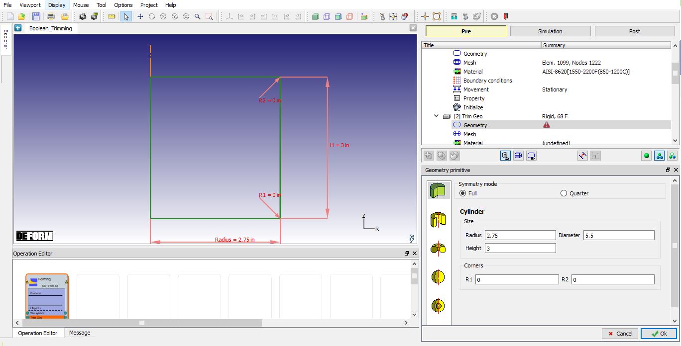
Geometry Primitive window
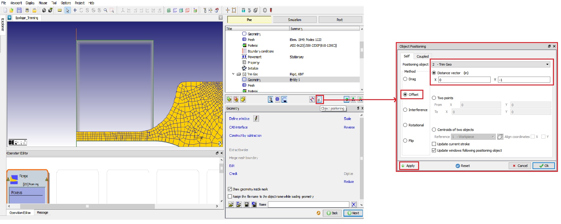
Positioning the Workpiece using Object Postioning option
Performing Boolean operation
Now Click on ![]() mode, select Workpiece object from Operation tree and click on Boolean (
mode, select Workpiece object from Operation tree and click on Boolean (![]() ) icon on Top line Menu (See Fig. 2DBTL1.9.).
) icon on Top line Menu (See Fig. 2DBTL1.9.).

Opening Boolean wizard by clicking on Boolean icon
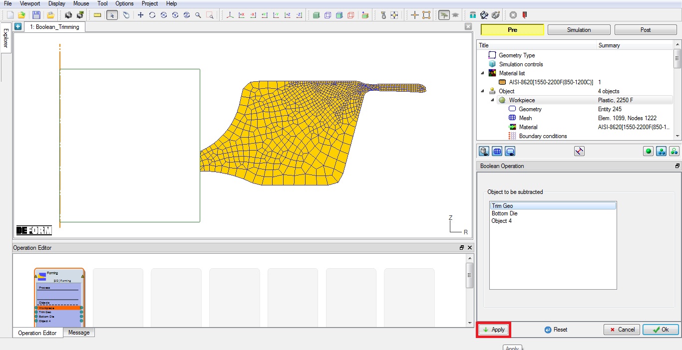
In Boolean wizard, select TrimGeo from Object to be subtracted list and click on ![]() button. After boolean, the workpiece will be as shown in Fig. 2DBTL1.10.
button. After boolean, the workpiece will be as shown in Fig. 2DBTL1.10.
Workpiece after boolean operation
Now we will setup Flash trimming operation. Go to WorkpieceMesh page.
Workpiece Mesh page
Define Target number of Elements as 5000 and no need to regenerate mesh. Click ![]() to Material page.
to Material page.
Defining Fracture data in Material
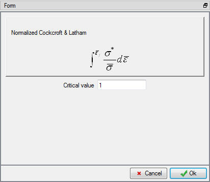
Click on ![]() button to define Fracture data, Click on Miscellaneous tab, select Normalized C &L Fracture model click on
button to define Fracture data, Click on Miscellaneous tab, select Normalized C &L Fracture model click on ![]() button and define Criticalvalue as 1 (See Fig. 2DBTL1.11.) Now Click
button and define Criticalvalue as 1 (See Fig. 2DBTL1.11.) Now Click ![]() and close the Material Edit window. Click
and close the Material Edit window. Click ![]() until Properties page.
until Properties page.
Workpiece material Fracture model window
Assigning Workpiece Fracture properties
Click on Fracture tab and select “Fractureelementdeletion “ from pull down menu and define FractureElements value as 2. Click ![]() to Top die page.
to Top die page.
Defining Top die object data for Flash trimming operation
Change the Objectname to “trim punch “, Keep the default temperature as 68 ° F and confirm the object type selected as rigid and Primary die. Click ![]() to Punch geometry page.
to Punch geometry page.
Import the trim punch geometry
Click the ![]() (Load geometry from a file) button and
(Load geometry from a file) button and ![]() open (import) the file “TrimPunch.IGS ” by browsing the geometry file path located in DEFORM installation folder *Tutorials***** directory. Check the geometry using
open (import) the file “TrimPunch.IGS ” by browsing the geometry file path located in DEFORM installation folder *Tutorials***** directory. Check the geometry using ![]() option to make sure the geometry is OK. Click
option to make sure the geometry is OK. Click ![]() until Punch movement page.
until Punch movement page.
Assigning movement controls to trim punch
The default mode is constant speed. Input a value of 3 in/sec for the Constant value and confirm that the Direction is -Y. Click ![]() until Bottom die page.
until Bottom die page.
Defining Bottom die object data
Change the Object name to “trim die “, Keep the defaulttemperature as 68 ° F and confirm that the object type selected is rigid. Click ![]() to trim die geometry page.
to trim die geometry page.
Import the trim die geometry
Click the ![]() (Load geometry from a file) button and
(Load geometry from a file) button and ![]() open (import) the file “TrimDie.IGS ” by browsing the geometry file path located in DEFORM installation folder **Tutorials** directory. Check the geometry using
open (import) the file “TrimDie.IGS ” by browsing the geometry file path located in DEFORM installation folder **Tutorials** directory. Check the geometry using ![]() option to make sure the geometry is OK. Click
option to make sure the geometry is OK. Click ![]() until Object 4page.
until Object 4page.
Defining Object 4 object data
Change the Object name to “trim flash holder “, Keep the default temperature as 68 °F and confirm the object type selected is rigid. Click ![]() to geometry page.
to geometry page.
Import the trim flash holder geometry
Click the ![]() (Load geometry from a file) button and
(Load geometry from a file) button and ![]() open (import) the file “TrimFlashHolder.IGS ” by browsing the geometry file path located in DEFORM installation folder **Tutorials** directory. Check the geometry using
open (import) the file “TrimFlashHolder.IGS ” by browsing the geometry file path located in DEFORM installation folder **Tutorials** directory. Check the geometry using ![]() option to make sure the geometry is OK. Click
option to make sure the geometry is OK. Click ![]() until Movement page.
until Movement page.
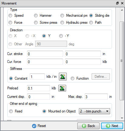
Assigning movement controls to trim flash holder
Select Slidingdie type movement radio button. Input a value of 1 klb/in as Constant Stiffness , 0.1klb as Preload , 3 “ as Max. disp, select “trim punch “ object in Mountedonobject list and confirm that the Direction is +Y (See Fig. 2DBTL1.12.). Click ![]() until Positioning page.
until Positioning page.
Trim Flash holder Movement page
Positioning object
Using Interferencemethod , position the Workpiece on Trim die in -Y direction, then position the trim flash holder on Workpiece in -Y direction and trim punch on Workpiece in -Y direction. Click ![]() until Contact page.
until Contact page.
Define Inter-object relations
Assign the default inter-object relationships using ![]() button. Click on the
button. Click on the ![]() button for one of the relationships. Select Shear type friction radio button, use the Constant radio button and define1 value. Click
button for one of the relationships. Select Shear type friction radio button, use the Constant radio button and define1 value. Click ![]() to exit the menu. Click
to exit the menu. Click ![]() to apply the friction value to the three other relationships. Click
to apply the friction value to the three other relationships. Click ![]() to Step controls page.
to Step controls page.
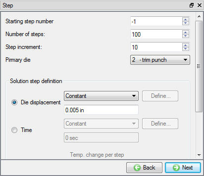
Assign Step controls
Define Number of steps as 100 , Step increment as 10 and define constant die displacement as 0.005 in/step as shown in Fig. 2DBTL1.13.
Step controls page
Data checking and database generation
Click on the ![]() button, the data checking system will confirm that all defined data is appropriate for running a simulation.
button, the data checking system will confirm that all defined data is appropriate for running a simulation.
Red marks indicate missing or incorrect data that will prevent a simulation from running. It is necessary to correct these errors before the database can be generated.
Yellow marks indicate data which may be suspect and should be reviewed. These should be investigated carefully, as they might result in system instability or erroneous (incorrect) results.
Review the data checking information. If there are no yellow or red marks, click the ![]() button.
button.
You should look for the words: Database has been generated. When you see this, it means that your inputs have been saved to the database and you are now ready to run the simulation.
Click on the MO ![]() Mode button (above the operation tree) to start the simulation.
Mode button (above the operation tree) to start the simulation.
Run and monitor a simulation
Click on the ![]() action label to open the Run Options dialog. Use the default Continue Run option to select “Continue from the last step ” (from step -1) option and then select the Simulation mode as Interactive and click on
action label to open the Run Options dialog. Use the default Continue Run option to select “Continue from the last step ” (from step -1) option and then select the Simulation mode as Interactive and click on ![]() button to run the simulation.
button to run the simulation.
Watching the simulation graphics provides an initial idea of what to expect when opening the post processor. Also monitor simulation from Simulation and log messages. The message file and log file will indicate that the simulation has been completed on the last line, confirming that click on ![]() mode button to review results.
mode button to review results.
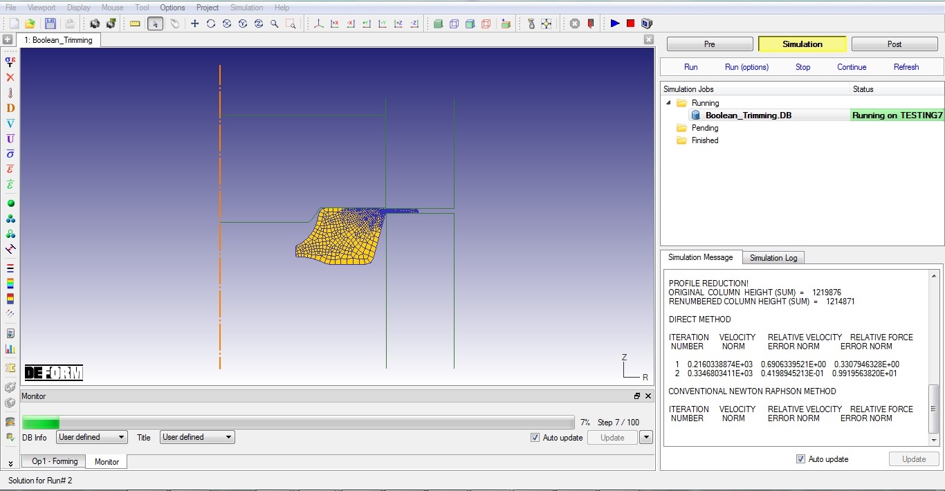
Running the simulation from MO simulation mode
Review Results
Play through the Steps and see the Damage distribution by plotting the Damage State variable.
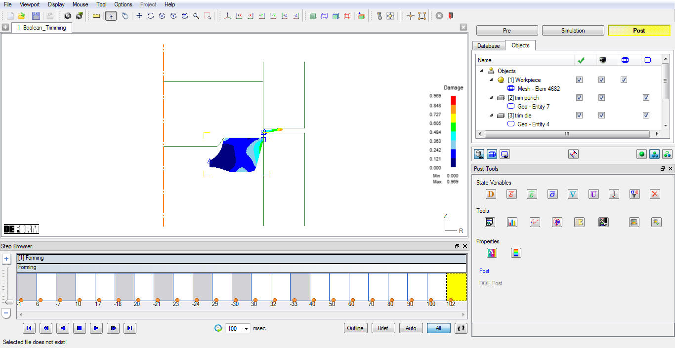
Damage distribution at last step