43.1. Shape Rolling Manual
43.1.1. How to add the Shape Rolling operation
43.1.2. Shape rolling operation in Operation Editor
43.1.3. Rolling Group Level
43.1.3.1. Process
43.1.3.2. Workpiece Page
-
Geometry 2D
-
Mesh 2D
-
Material page
-
BCC Page (Rolling Group)
43.1.3.3. Groove List page
43.1.3.4. Pass Table
-
First HT
-
Multi Pass Setup
-
Rollset Type
-
Defining Roll Groove Geometry in Pass Table
-
Roll Speed
-
Roll Gap
-
Rotation (deg)
-
Reverse rolling (For Lagrangian rolling type)
-
Show all rolls (For asymmetric rolling)
-
Running 2.5D Simulation
-
Stand Table
-
Stand Settings
43.1.3.5. 3D Setup Page
-
3D Roll geometry settings
-
3D Roll mesh settings
-
3D Workpiece settings
-
3D setup page for ALE Rolling type
-
3D Setup page for Lagrangian Rolling type
43.1.3.6. Simulation Controls
43.1.3.7. Generate DB
43.1.4. Shape Rolling Pass Level
43.1.4.1. Stand Table
43.1.4.2. Roll Stand Page
-
Roll Geometry Page
-
Roll Mesh Page
-
Roll Movement page
43.1.4.3. Table/Guide geometry page
43.1.4.4. Workpiece Object page
-
Workpiece Mesh
-
Workpiece BCC
-
Workpiece Movement
-
Workpiece Initialize
-
Workpiece Built-in Flownet
43.1.4.5. Positioning
43.1.4.6. Scheduled Positioning
43.1.4.7. Contact
43.1.4.8. Simulation Controls
43.1.4.9. Generate DB
How to add the Shape Rolling operation
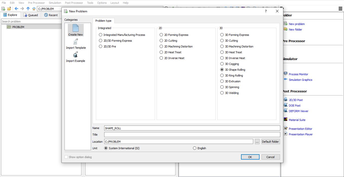
Shape rolling operation can be setup in Integrated Manufacturing Process environment that can be accessed from “GUI Main”. Create a new problem by either selecting File ![]() New Problem or by clicking the
New Problem or by clicking the ![]() icon. Select “3D Shape Rolling” radio button under problem type and unit system as shown in Fig. 43.1.1.. Click
icon. Select “3D Shape Rolling” radio button under problem type and unit system as shown in Fig. 43.1.1.. Click ![]() button. Integrated Manufacturing Process wizard will open, we can see that 3D Shape rolling operation is added in Operation editor.
button. Integrated Manufacturing Process wizard will open, we can see that 3D Shape rolling operation is added in Operation editor.
Adding Shape Rolling Operation from GUI Main
We can also add shape rolling operation into Integrated Manufacturing Process environment from the New Project pop-up when a new problem is opened in Integrated Manufacturing Process environment as shown in Fig. 43.1.2. Using “Copy Existing project” option, we can import previous saved projects as new project from the New Project pop-up.
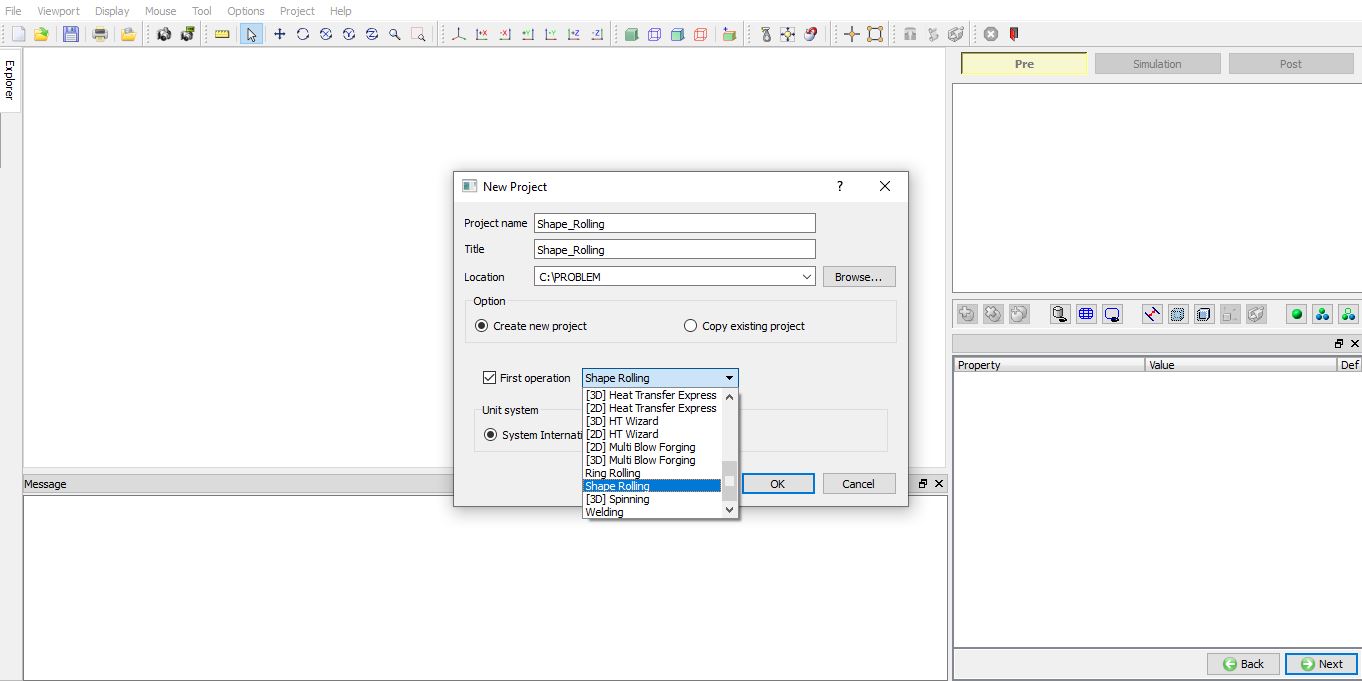
Assign Project name and select First Operation in New Project window
We can also add Shape Rolling operation to operation editor from explorer tab in Integrated Manufacturing Process environment, by clicking on ![]() button next to “Shape Rolling” operation (as shown in Fig. 43.1.3.) or by drag and drop “Shape Rolling” operation into operation editor window. As the “Shape Rolling” operation is added into operation editor Process selection page will be opened in property settings modification window.
button next to “Shape Rolling” operation (as shown in Fig. 43.1.3.) or by drag and drop “Shape Rolling” operation into operation editor window. As the “Shape Rolling” operation is added into operation editor Process selection page will be opened in property settings modification window.

Adding Shape Rolling operation from Explorer Operation list
Shape rolling operation in Operation Editor
Shape Rolling Operation is set in two different stages, “Rolling Group” level and “Rolling Pass” level. In “Rolling Group” stage, we will be defining the operation at top level with objects 2D cross-section (both Workpiece and Grooves) and Pass information. User can generate 3D objects with this information and then define Simulation controls. If there is no specific change to be modelled at pass level, user can start the simulation with this data. The simulation controls and other process definition defined at Rolling Group is common to all passes. At Rolling Pass stage user can make specific changes to each pass such as add and remove tables/Guides, add and remove Stations, define remeshing conditions and so on.
After adding the Shape rolling operation in Operation Editor, we will observe the Orange ribbon around the Rolling pass operation (as shown in Fig. 43.1.4.) which means we are at Rolling Group stage. When we select the Rolling pass Operation than the Rolling Group orange ribbon turns to blue and the selected Rolling Pass will be highlighted with Orange border as shown in Fig. 43.1.5.

Rolling Group Level is selected
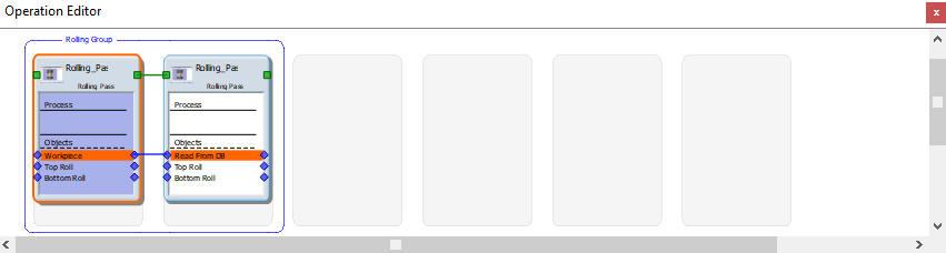
Rolling Pass Operation selected
Rolling Group Level
Process
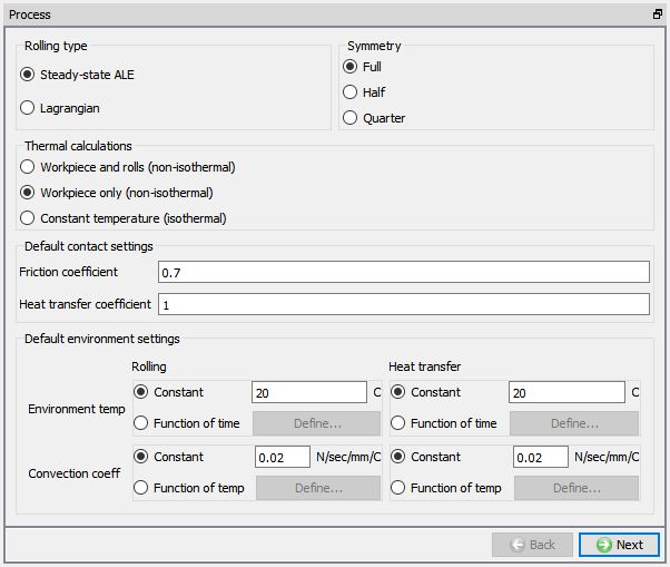
In Process page user will be specifying the process settings and select the type of Rolling simulation to be performed.
Rolling type : The rolling template has two different rolling types. One is steady state ALE rolling and other is Lagrangian (incremental) rolling.
Lagrangian Rolling Type: In Lagrangian rolling type, initial workpiece shape is modelled same as actual workpiece and during simulation the workpiece is displaced (deformed) incrementally in all directions based on the output of incremental equations and state variable values are updated. It takes longer period for completion of the simulation since simulation must be continued until the workpiece passes through the last roll set to visualize the output of rolling process, also displacement is calculated in all directions and updated.
ALE Rolling Type : In ALE (Augmented Lagrangian Eulerian) Rolling type, initial workpiece is modelled approximately closer to the output shape (2.5D simulations are used for better approximation) and workpiece is displaced only in Y and Z directions but not in rolling direction and state variable values are updated. ALE Simulations can be stopped when steady state is reached based on ALE Stopping criteria, steps required to achieve steady-state depends on how close we can model initial workpiece conditions to steady-state condition. ALE Simulations usually take less time for simulation and will be helpful to visualize rolling process output quickly.
Thermal Calculations : In thermal calculations page (see Fig. 43.1.6.) options are available to select the object types on which thermal calculations need to be performed. User has options to select Calculations in workpiece alone or even in rolls in case of non-isothermal or at constant temperature in case of isothermal models. User can select Calculations in workpiece alone or even in rolls in case of hot rolling process setup. In case of cold rolling process user can select constant temperature or Calculation in workpiece alone to study the temperature change in workpiece.
Symmetry: In symmetry tab (see Fig. 43.1.6.), we have options to select full model or half symmetry or Quarter symmetry depending on the geometry symmetry to be modelled in the setup.
Friction coefficient : We can define the friction coefficient value between rolls and workpiece. This friction co-efficient value is applied between all rolls and workpiece for all the passes, user can modify this value at Rolling Pass level if required (See Fig. 43.1.6.).
Heat transfer Coefficient : We can define the heat transfer coefficient value which will be applied for all the passes from process page(See Fig. 43.1.6.).
Default environment settings : We can define the Environment temperature and Convection coefficient values for both Rolling and Heat transfer simulations in Process page which are then applied to all the Rolling Pass and Heat transfer operations respectively (See Fig. 43.1.6.). We can also customize this environment settings for each pass from Pass table page (See Fig. 43.1.6.)
Process settings definition
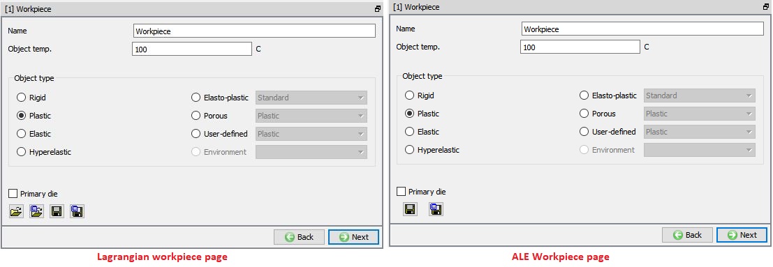
Workpiece Page
We can define the temperature and object type of a workpiece in this page as shown in the Fig. 43.1.7. Plastic object type is selected by default, if user is interested to consider the effect of elastic properties then Elasto-plastic object type can be used. User can import objects from other databases or key files using ![]() ,
, ![]() options or save the object data using
options or save the object data using ![]() ,
, ![]() options.
options.
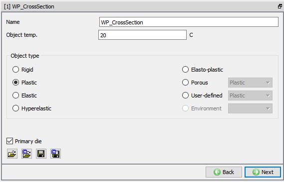
Workpiece object definition page
-
Geometry 2D
The sectional geometry of the stock can be imported from a file using ![]() ,
, ![]() options or can be created from the
options or can be created from the ![]() (primitives). Modifications to the imported or created geometry can be made using
(primitives). Modifications to the imported or created geometry can be made using ![]() option. The geometry can be saved using
option. The geometry can be saved using ![]() ,
, ![]() options.
options.
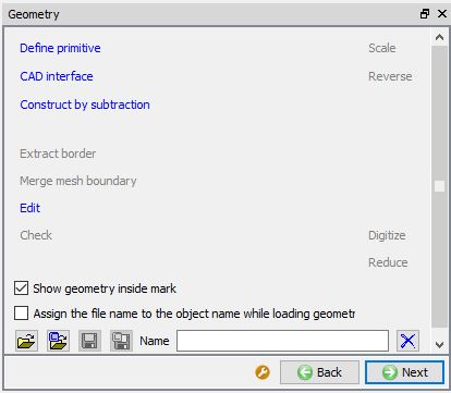
Geometry page
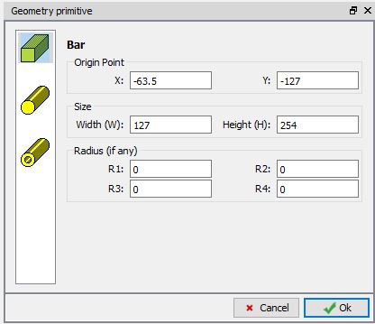
Geometry primitive page
-
Mesh 2D
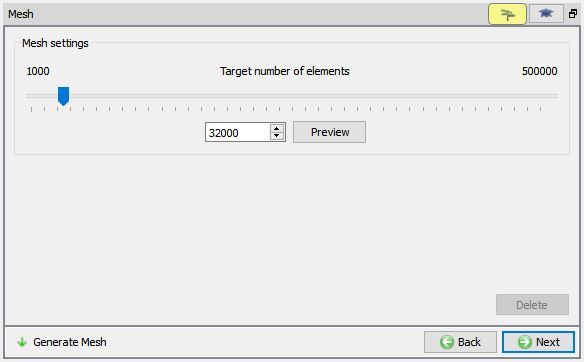
We can generate the 2D Cross Section mesh by defining the number of elements in guided mode. Advanced options to control 2D mesh generation can be accessed using expert mode ![]() toggle button from tool bar. For more information please refer to 13.1. 2D Mesh Genearation.
toggle button from tool bar. For more information please refer to 13.1. 2D Mesh Genearation.

Guided mode mesh settings
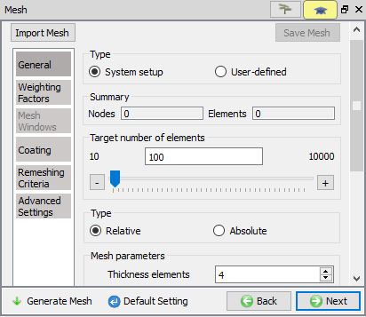
Expert mode mesh settings
-
Material page
In material page, all the materials added to material list are displayed (As shown in Fig. 43.1.12.). User can select the required material to assign it to respective object. If the desired material is not available in the list, then the user can load the material in object material page using Import Material data from a file ![]() or Using Load form Library option
or Using Load form Library option ![]() . User can also create new material if the material is not available in DEFORM library using
. User can also create new material if the material is not available in DEFORM library using ![]() . User can delete the material from list using
. User can delete the material from list using ![]() or edit the material data using
or edit the material data using ![]() . Modified / newly defined Material can be saved using
. Modified / newly defined Material can be saved using ![]() ,
, ![]() options.
options.
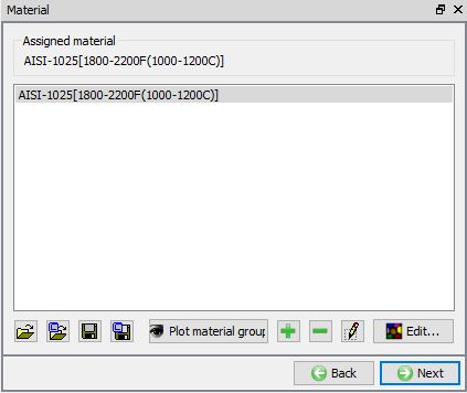
Material page
-
BCC Page (Rolling Group)
In Boundary conditions page, user can assign various boundary constraints to an object. Boundary conditions specify how the boundary of an object interacts with other objects and with the environment. Commonly used boundary conditions are heat exchange with the environment for simulations involving heat transfer, prescribed velocity for enforcing symmetry and Contact between objects in the model. Fig. 43.1.13. shows various BCC that can be assigned to an object at Rolling Group stage.
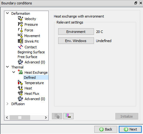
BCC page
Groove List page
In groove list page, user can create or load the rolls groove cross-sections that are used in the operation. We can add a groove by clicking on the ![]() button. After adding a groove, we need to select the respective groove and define the groove geometry by using the
button. After adding a groove, we need to select the respective groove and define the groove geometry by using the ![]() or
or ![]() button. Several pre-defined roll designs are available for user to select else user has an option to create rolls from primitives. We can also define the Rotation centre and axis of the grooves as shown in the Fig. 43.1.14. Using the
button. Several pre-defined roll designs are available for user to select else user has an option to create rolls from primitives. We can also define the Rotation centre and axis of the grooves as shown in the Fig. 43.1.14. Using the ![]() button we can save the Groove list to a file and using
button we can save the Groove list to a file and using ![]() button we can import the Groove list.
button we can import the Groove list.
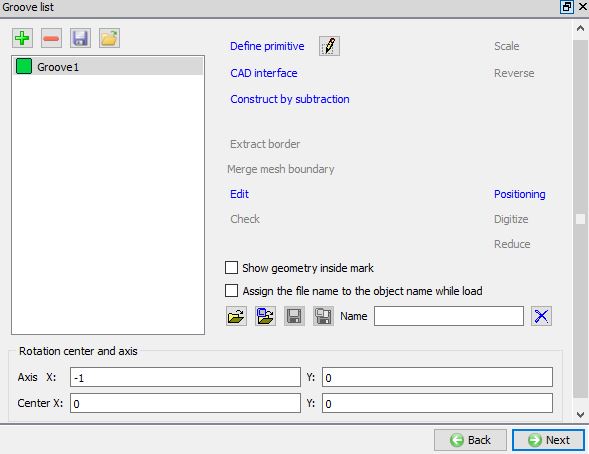
Groove List Page
Defining the Groove geometry using Define Primitive
**When we click on![]() label, Roll groove primitives window will be opened as shown in the Fig. 43.1.15. We can select any one of the groove shapes, define its parameter and then click on
label, Roll groove primitives window will be opened as shown in the Fig. 43.1.15. We can select any one of the groove shapes, define its parameter and then click on ![]() to create the groove geometry.
to create the groove geometry.
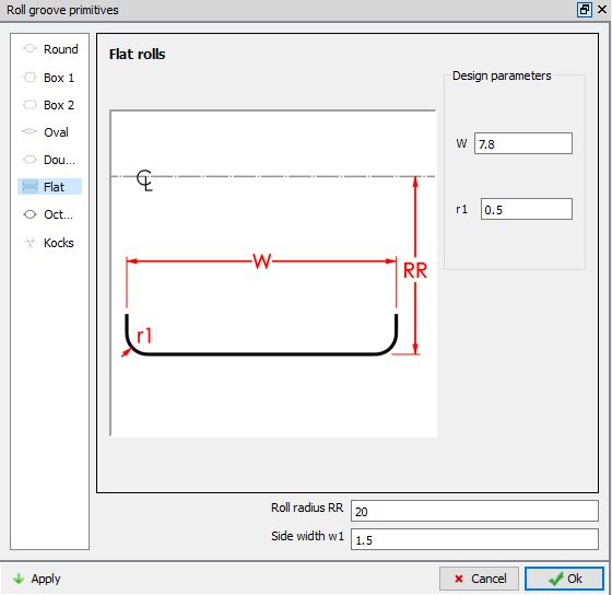
Roll Groove Primitive window
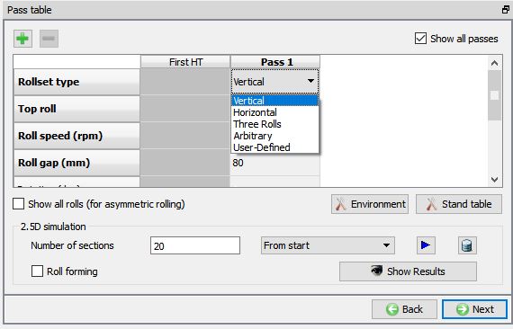
Pass Table
In pass table, user can define number of passes and stands in each pass along with the pass setting as shown in Fig. 43.1.16. In this pass table, user can define the Rollset type, select Roll Grooves to be used, Roll speed (rpm), Roll Gap (mm), workpiece Rotation (deg) before entering the pass, Roll temperature, Transfer time to the next pass after completion of the current pass and Customize environment check box to modify the environment settings if they are different from the default values defined in the Process page or using Environment button in the Pass table page.
First HT
This is used to simulate a heat transfer operation only for the workpiece before the Pass 1 operation. User can activate First HT Operation to simulate transfer time from the furnace to Pass1. For all other passes user can use “Transfer Time” in pass table to specify the time between end of current selected pass and next pass.
Multi Pass Setup
**We can define multiple passes in rolling operation by clicking one![]() button in pass table. If user wants to delete any pass, select the respective pass and click on
button in pass table. If user wants to delete any pass, select the respective pass and click on ![]() button. We can also observe the operation editor that as we increase / decrease the passes, the shape rolling pass tiles are added / deleted respectively. From V14.0, when we click on
button. We can also observe the operation editor that as we increase / decrease the passes, the shape rolling pass tiles are added / deleted respectively. From V14.0, when we click on ![]() button it will add the new pass by copying the previous pass table data.
button it will add the new pass by copying the previous pass table data.

Pass Table Page
Rollset Type
Depending on the arrangement of rolls at the roll stand user can select the Rollset type from pull down menu as shown in Fig. 43.1.17. Depending on the Rollset type selected, the rolls are positioned automatically by the system. User must define number of rolls and their position in case of arbitrary Rollset type.
Arbitrary Rolls
Arbitrary rolls are used for the problems in which the rolls are placed in specific way to meet special requirements. These rolls can be placed at any arbitrary position in space to which any value can be assigned as per the problem requirement. Basic steps followed in setting up the arbitrary roll design.
-
Define groove geometry in Groove list page (as shown in Fig. 43.1.14.).
-
In Pass table page select Arbitrary option as Rollset type in a Pass, select the Pass and click on
 (as shown in Fig. 43.1.18.).
 -
Select the Stand 1 and click on
 button. In stand settings define Number of rolls. Define the Angle with neighbouring roll and select groove geometry for all the rolls from the list. Click
  button (as shown in Fig. 43.1.19.).
 -
Define the Roll Gap and Roll Speed in the stand table and click
button (as shown in Fig. 43.1.20.). -
Click
 to 3D setup page and generate the 3D geometry and observe (as shown in Fig. 43.1.21.).
Assigning Rollset type

Selecting Arbitrary rollset type
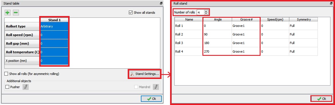
Defining Stand Settings

Defining Stand Details
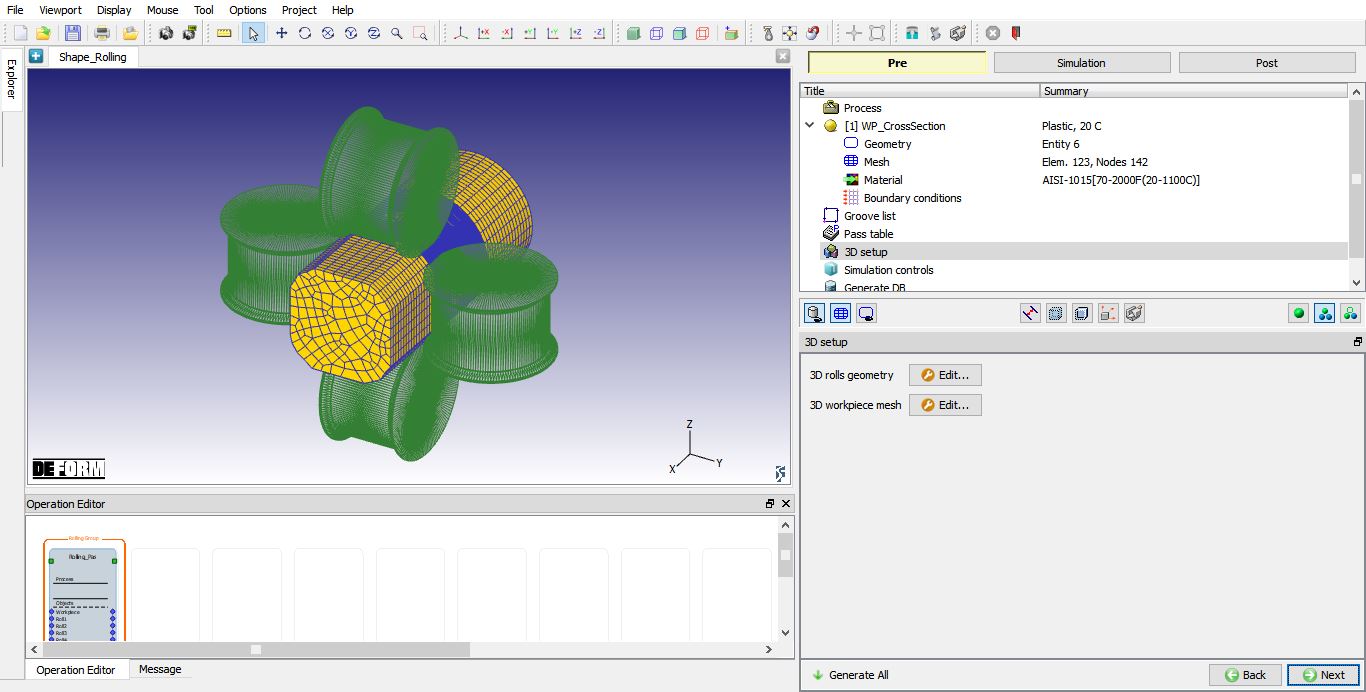
Arbitrary roll set (Four rolls)
####
Defining Roll Groove Geometry in Pass Table
Several pre-defined roll designs are available for user to select else user has an option to create rolls from primitives in “Groove list” page. User can select the groove from the pull-down menu in “Top roll”/ “Bottom roll” row. Both Top and Bottom roll are visible in the Pass Table/Stand Table when the rolls are asymmetric. User can activate Asymmetric rolling by checking the check box next to “Show all Rolls”. When roll geometry is not created from the available primitives, it is important to pay attention to the cross section, the roll center, roll axis and roll diameter data.
Roll Speed
User can define the roll speed in “Roll Speed” row. This roll speed is applied to all rolls, if user wants to have differential rolling speed then it can be defined in movement page of the respective object at Pass stage.
####
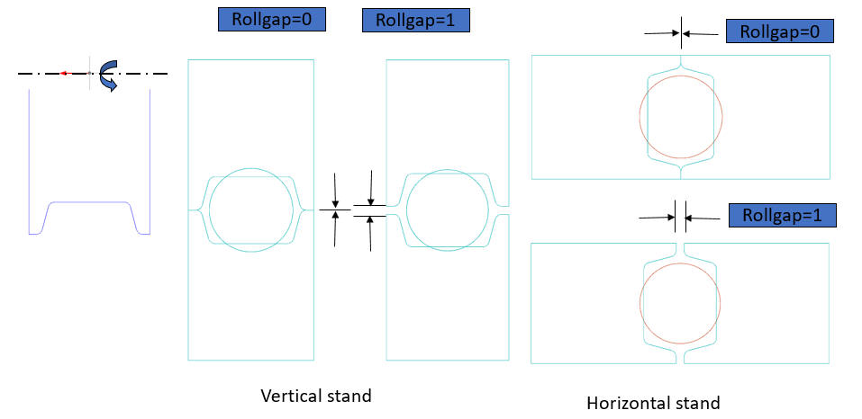
Roll Gap
“Roll gap” is the distance used to position rolls using bounding box. This is the distance between Top and Bottom rolls as shown in the Fig. 43.1.22.
Roll Gap definition
For User-defined Rollset type the rolls must be positioned manually instead of the automatic positioning (using bounding box method) as shown in the Fig. 43.1.23. It will be useful when roll geometry is already positioned appropriately.
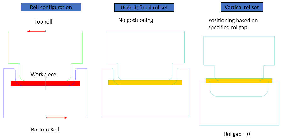
Roll Gap definition for User defined rollset
Rotation (deg)
The user can define the rotation of the workpiece before the simulation of the pass is started. The workpiece will rotate by the amount specified in Rotation (deg) before it is positioned with rolls. This option is not available at the first pass, quarter symmetry Lagrangian model and for Half symmetry model. For Full model, user is allowed to enter the angle and it is available for both ALE and Lagrangain rolling types as shown in the Fig. 43.1.24.. For quarter symmetry ALE model, we are allowed to rotate only by 90 deg by turning on the check box as shown in the Fig. 43.1.25.
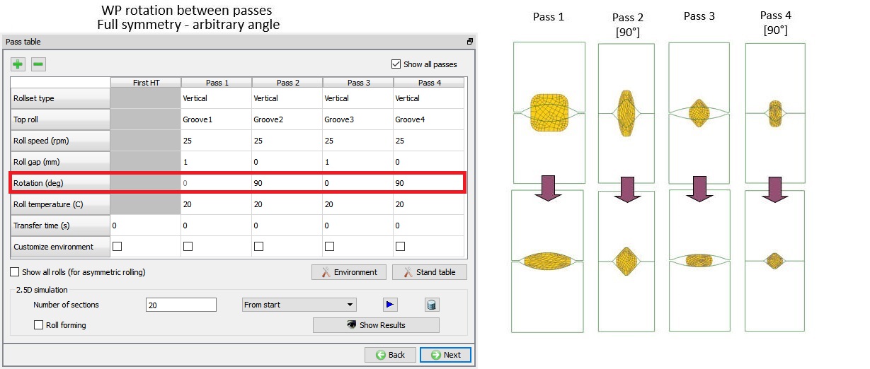
Rotation between passes for Full Model
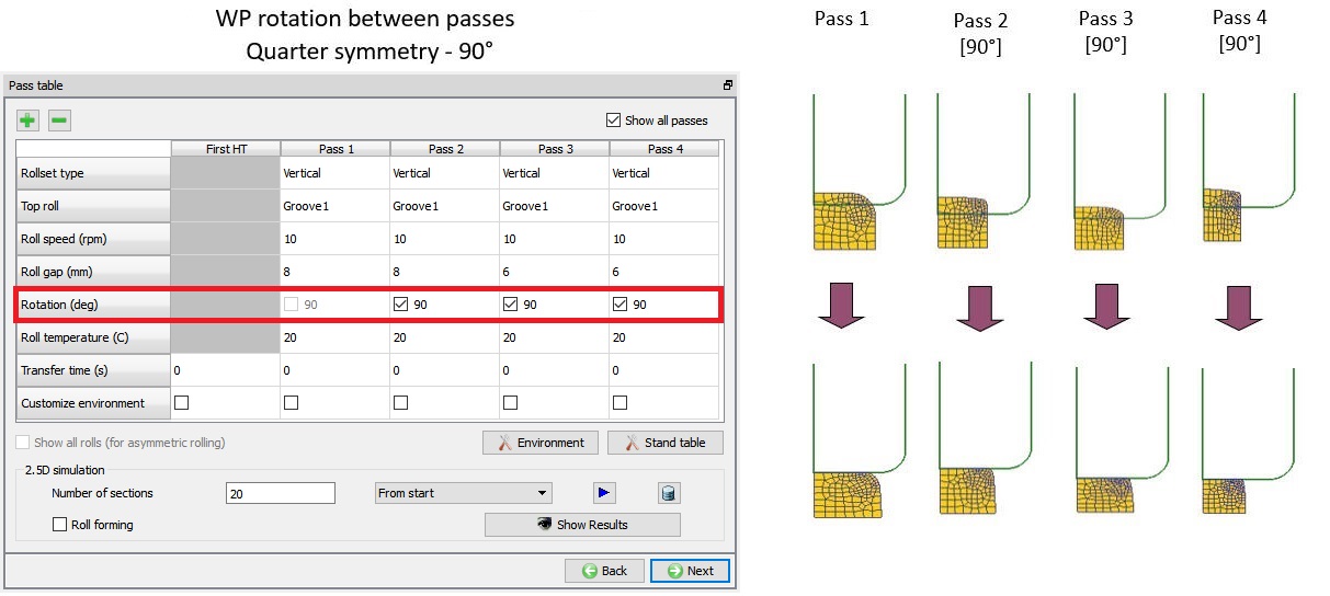
Rotation between passes for quarter Model
Reverse rolling (For Lagrangian rolling type)
For Lagrangian type rolling simulation, by default the workpiece is assigned movement to move in +X axis direction, but when we turn ON the Reverse rolling check box, the workpiece movement is reversed with respect to the previous pass so that we can have to and fro motion for the workpiece as shown in the Fig. 43.1.26..
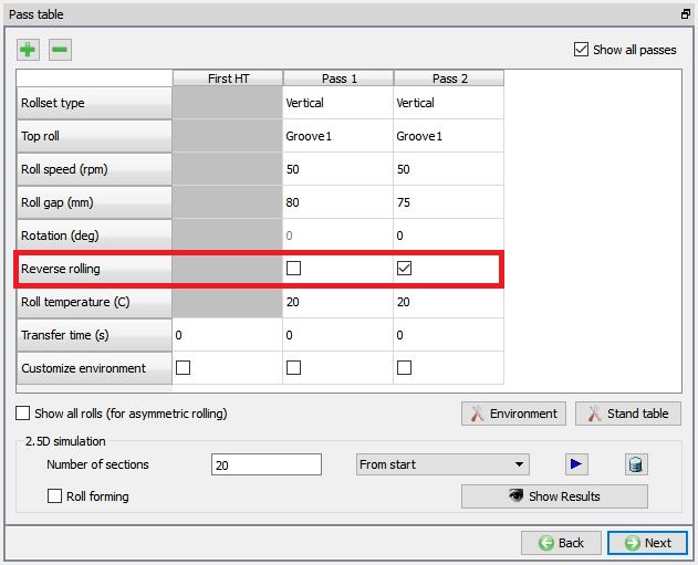
Reverse rolling option for Lagrangian type rolling simulation.
Show all rolls (For asymmetric rolling)
This check box is checked when we want to setup an asymmetric rolling. When this check box is activated, user can define different grooves for Top roll and Bottom roll as shown in the Fig. 43.1.27.
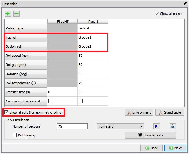
Defining asymmetric rolling
Running 2.5D Simulation
This simulation is mostly used for the ALE Rolling Type to generate initial workpiece shape. 2.5D Simulation will provide information about approximate deformation levels in workpiece at the end of rolling. To use the 2.5D simulation user can define Number of sections along the contact between the Rolls and workpiece and click on ![]() button (by default From start option is selected in the combo box). When we click on
button (by default From start option is selected in the combo box). When we click on ![]() button, 2.5D simulation will start to simulate and message file is updated as the simulation progress. If we want to stop the 2.5D simulation, we can click on
button, 2.5D simulation will start to simulate and message file is updated as the simulation progress. If we want to stop the 2.5D simulation, we can click on ![]() button and after completion of simulation, click
button and after completion of simulation, click ![]() to close and view the results.
to close and view the results.
From v14.0, user can rerun the 2.5 D simulation or continue from the simulation selected from the combo box. After completion of the 2.5D simulation, the combo box contains all the simulations that 2.5D database contains and user can select one of them to continue from (See Fig. 43.1.28.).
The Roll Forming check box is Useful for thin sections or sheet forming, where bending is more dominant than deformation.
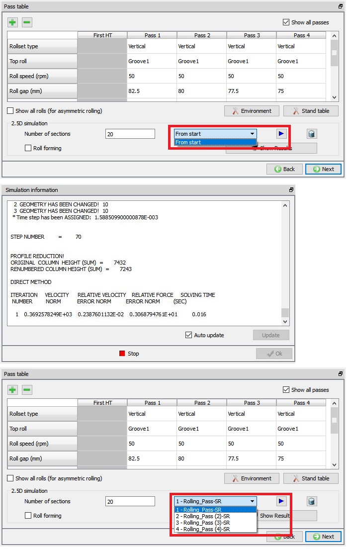
Simulation message file during 2.5D simulation
To view the 2.5 D simulation results, click on ![]() button. We will observe the Rolling pass Result table as shown in Fig. 43.1.29. We can also plot state variable using state variable pull down menu and selecting respective state variable. Click
button. We will observe the Rolling pass Result table as shown in Fig. 43.1.29. We can also plot state variable using state variable pull down menu and selecting respective state variable. Click ![]() to close the Results page. The user can open the 2.5D simulation results in the Post Processor by clicking on the
to close the Results page. The user can open the 2.5D simulation results in the Post Processor by clicking on the ![]() button. We can observe that every cross-section result is stored in each step sequentially and for each pass there is a separate operation.
button. We can observe that every cross-section result is stored in each step sequentially and for each pass there is a separate operation.
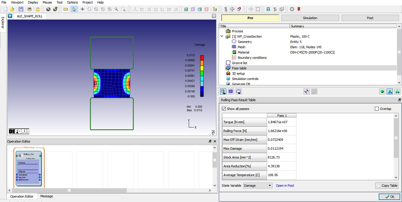
Simulation results of 2.5D Simulation
####
Stand Table ![]()
A pass can have a single stand or multiple stands. If a pass is having multiple stands than user can select the respective pass and then click on the ![]() button to open the Stand table window of the respective pass. In stand table user can add stands or remove stands using
button to open the Stand table window of the respective pass. In stand table user can add stands or remove stands using ![]() and
and ![]() buttons. Distance between the current stand and previous stand is specified in “X position”. User can select the respective stand column and click on the
buttons. Distance between the current stand and previous stand is specified in “X position”. User can select the respective stand column and click on the ![]() button. We can run the 2.5D Simulation for Multi stands in stand table like in Pass table (See Fig. 43.1.30.).
button. We can run the 2.5D Simulation for Multi stands in stand table like in Pass table (See Fig. 43.1.30.).
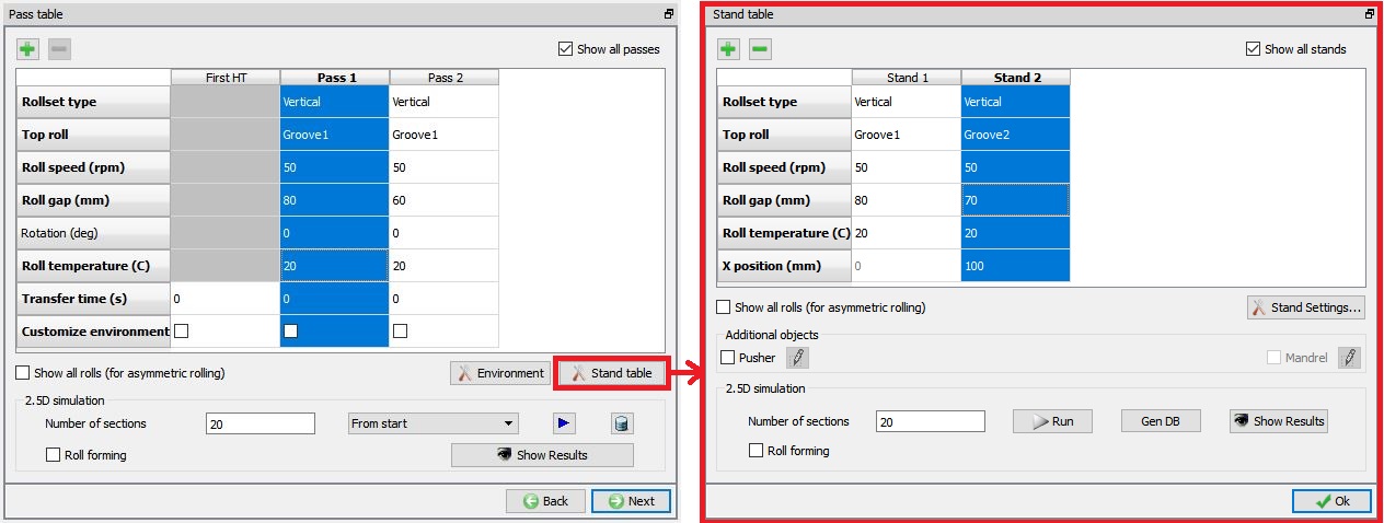
Multi Stand Table Page for Pass 1
####
Stand Settings ![]()
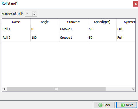
In Stand settings, user can select the Groove design of the rolls and define its speed. In case of arbitrary and user-define rolls, we can define the roll angle with the neighbouring roll. It also shows the Symmetry data of the rolls as shown in the Fig. 43.1.31
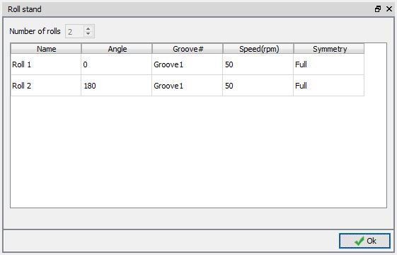
Roll Stand Settings Page
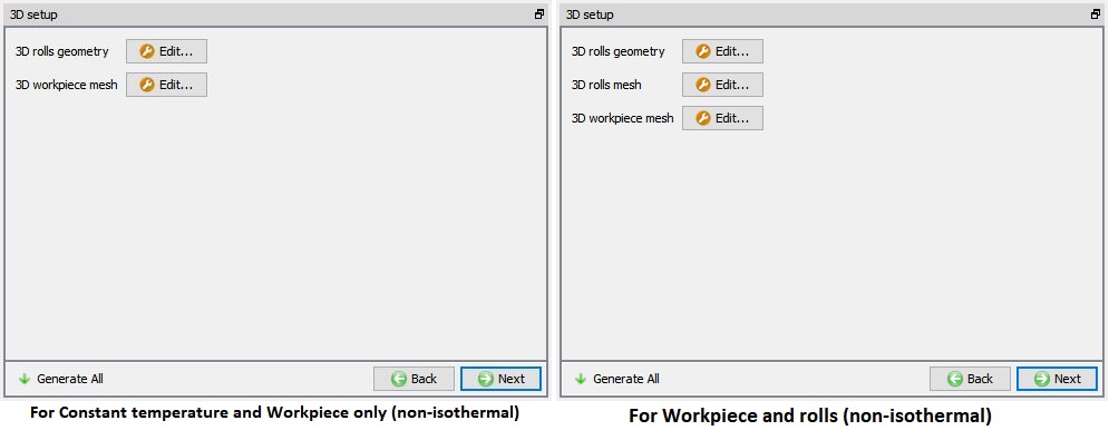
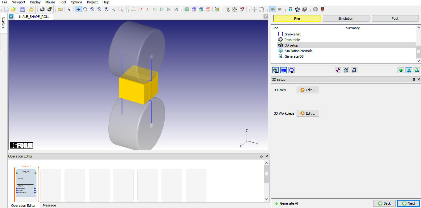
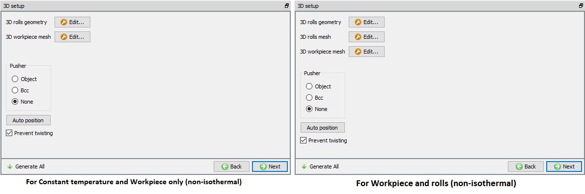
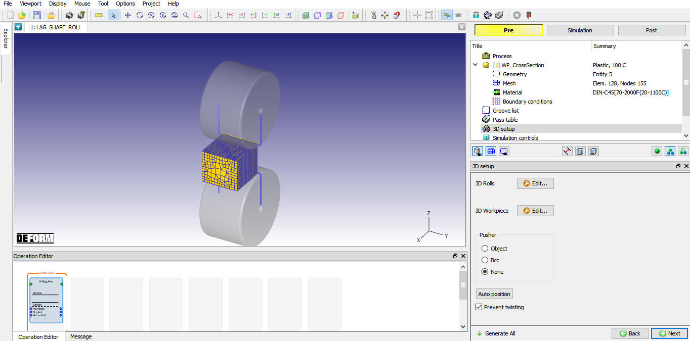
3D Setup Page
User can define settings to convert 2D- Cross section into 3D geometry in this page. These settings are different for Lagrangian and ALE Rolling types.
3D setup page for ALE Rolling type
3D setup page for ALE Rolling is as shown in Fig. 43.1.32. User can click on ![]() button next to 3D rolls geometry, 3D rolls mesh and 3D Workpiece mesh to modify the respective settings. 3D settings for rolls geometry are as shown in the Fig. 43.1.33. 3D rolls mesh options as shown in the Fig. 43.1.34. 3D workpiece mesh options as shown in the Fig. 43.1.35.
button next to 3D rolls geometry, 3D rolls mesh and 3D Workpiece mesh to modify the respective settings. 3D settings for rolls geometry are as shown in the Fig. 43.1.33. 3D rolls mesh options as shown in the Fig. 43.1.34. 3D workpiece mesh options as shown in the Fig. 43.1.35.
After defining the settings for both 3D Workpiece and 3D Rolls, user can click on ![]() button in the 3D setup page to generate 3D geometries and mesh, setup looks like as shown in the Fig. 43.1.39.
button in the 3D setup page to generate 3D geometries and mesh, setup looks like as shown in the Fig. 43.1.39.
ALE Rolling Type 3D Setup Page
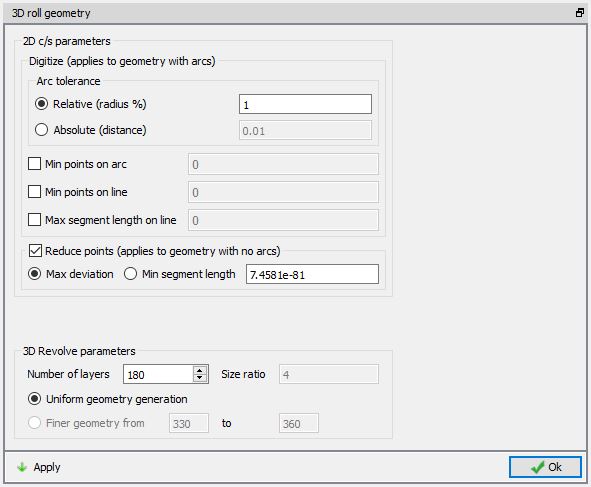
3D roll geometry settings
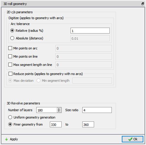
3D Roll Geometry page for ALE Rolling type
-
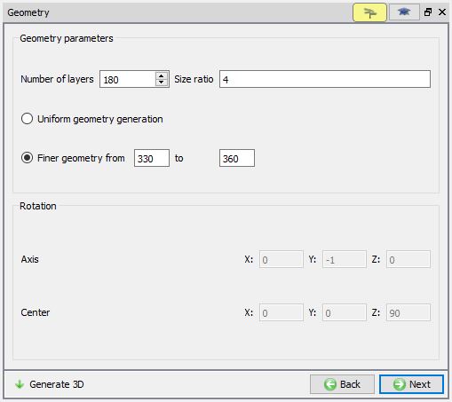
Number of Layers: User can define number of layers along the rotation of the 2D cross-section.
-
Size ratio: If user is having a finer geometry then the size ratio between maximum size to minimum size in the Finer geometry region can be defined here.
-
Uniform Geometry option: When user uses this radio button, the 3D geometry will be generated with uniform layer thickness along the rotation of the 2D cross-section.
-
Finer Geometry from: If user would like to have finer geometry at the contact region to increase the accuracy of the calculations, then user can specify the start and end angle of the finer geometry.
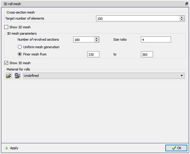
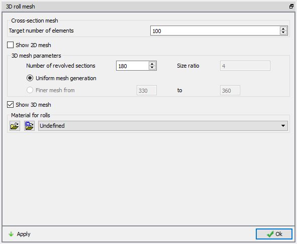
3D roll mesh settings![]()
This option will be available only after selecting the Workpiece and rolls (non-isothermal) option from the process page. In roll mesh settings page, user can define the number of elements for 2D Cross section mesh, 3D mesh parameters and material for rolls. These settings are applied for all rolls. User can modify these settings from respective pass.
3D Rolls Mesh generation page for ALE Rolling Type
-
Cross section : User can define the target number of elements for 2D cross section mesh.
-
Uniform mesh generation : When user uses this radio button, the 3D mesh will be generated with uniform layer thickness along the rotation of the 2D cross-section.
-
Finer mesh from : If user would like to have finer mesh at the contact region to increase the accuracy of the calculations, then user can specify the start and end angle of the finer mesh.
-
Materialforrolls : We can assign the material for rolls by importing material data from a file or library.
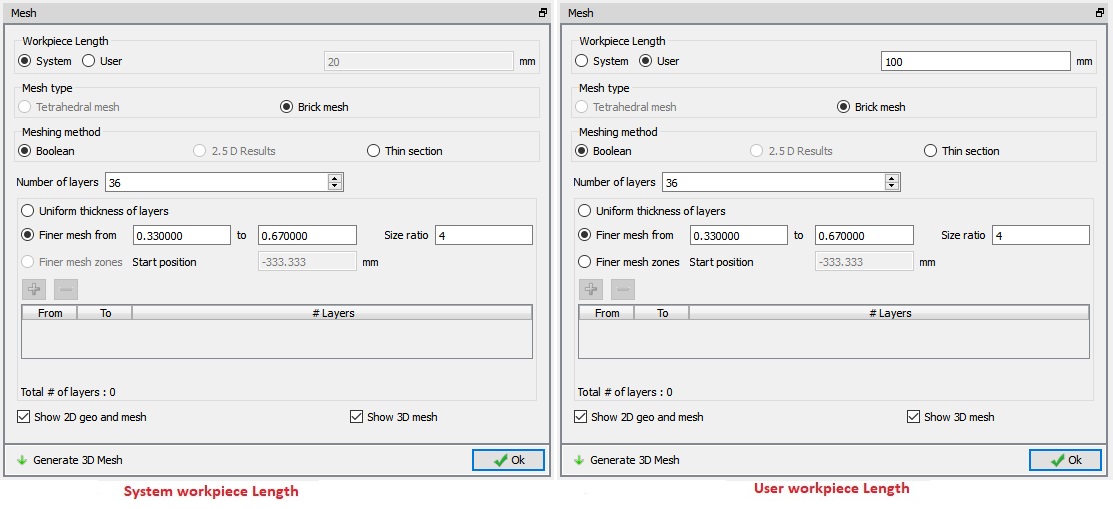
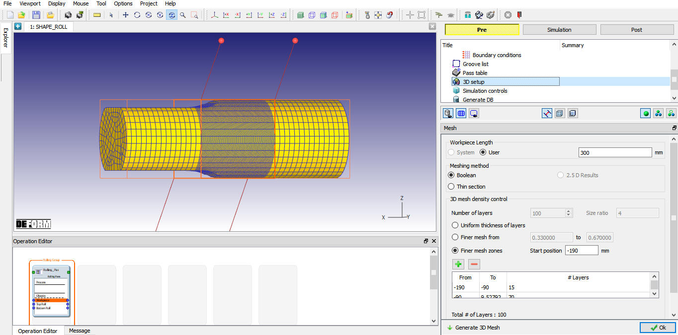
3D Workpiece settings
In workpiece settings page user can define the Workpiece length, meshing method and mesh settings to be used while generating 3D shape.
3D Workpiece Mesh generation page for ALE Rolling Type
-
Workpiece length: User can choose “System” defined length or select “User” and define custom size as require.
-
Meshing method: They are 3 methods available for meshing in ALE type of rolling,
-
Boolean: The workpiece shape is created and meshed by performing boolean operation at the contact of roll and workpiece.
-
2.5D Results: The workpiece shape at the contact of roll and workpiece is created and meshed based on the 2.5 D results.
-
Thin Section: This option is used when thin sheets are simulated. The workpiece shape is created and meshed similar to Boolean operation, but more layers are added along the thickness.
-
3D Mesh density control
-
Number of Layers: Number of layers to be used along the rolling direction to generate workpiece mesh is defined here.
-
Size Ratio: When finer mesh is used closer to the contact zone for accurate results then size ratio will be used to determine the layers thickness. It is the ratio between the maximum layer thickness and minimum layer thickness.
-
Uniform Thickness of layers: If user would like to create a workpiece with constant layer thickness along the rolling direction then user can select this option. Mesh generated with “UniformThickness of layers ” will look like as shown in the Fig. 43.1.36.
-
Finer mesh from: Finer mesh from is used to define the start and end point of the finer mesh. It is defined between 0 to 1, 0 is the start of the workpiece and 1 is end of the workpiece. Workpiece mesh generated with “Finer mesh from” looks like as shown in the Fig. 43.1.37.
-
Finer mesh zones: Using this Option, the user can define the different zones with different number of layers in each zone. Starting position is the absolute distance from which mesh zones are created, by default it is exit end of workpiece. Workpiece mesh generated with “Finer mesh zones” looks like as shown in the Fig. 43.1.38.

Mesh generation using “Uniform thickness of layers” option
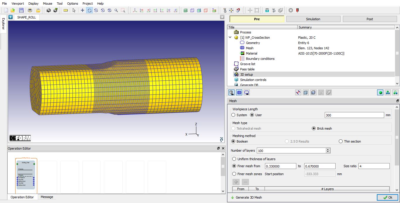
Mesh generation using “Finer mesh from” option
Mesh generation using “Finer mesh zones” option
3D setup for ALE Rolling type
3D Setup page for Lagrangian Rolling type
3D setup page for a Lagrangian Rolling type is as shown in Fig. 43.1.40. In addition to the 3D Roll and 3D Workpiece settings, we have Pusher settings, Auto position and Prevent twisting. After defining the 3D Workpiece, 3D Rolls and Pusher settings, click on ![]() button in the 3D setup page to generate 3D geometries and mesh, setup looks like as shown in the Fig. 43.1.44.
button in the 3D setup page to generate 3D geometries and mesh, setup looks like as shown in the Fig. 43.1.44.
-
3D Roll settings
: The settings are similar to ALE 3D Roll settings, except that we do not have options to create finer geometry as shown in the Fig. 43.1.41. -
3D Roll mesh settings
: The settings are similar to ALE 3D Roll mesh settings, except that we do not have options to create finer mesh as shown in the Fig. 43.1.42. -
3D Workpiece settings
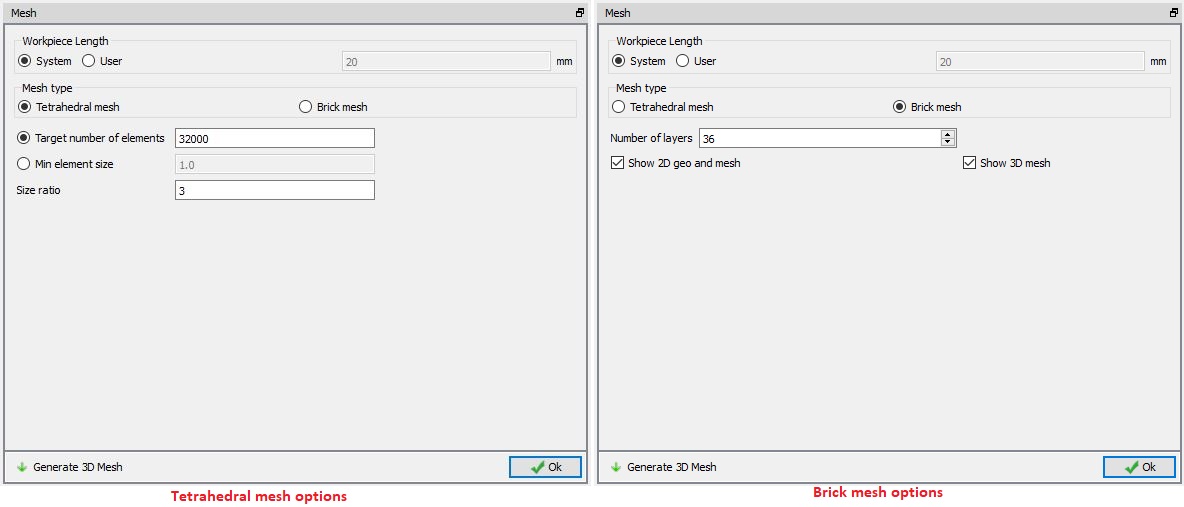
: We can use the Tetrahedral or Brick mesh type to generate mesh for the workpiece in Lagrangian rolling type as shown in the Fig. 43.1.43. -
Pusher: User may use pusher to push the workpiece towards the rolls with some speed to complete the shape rolling simulation. “None” can be selected if user does not want to use pusher. If user wants to use pusher then pusher can be defined as,
-
Object: When this option is selected a separate rigid Pusher object is created with default velocity calculated based on the Roll speed. The object dimensions and mesh can be modified at Pass stage Pusher object settings.
-
BCC: When this option is selected, it eliminates artificial distortion at the end of the workpiece resulting from contact with pusher. This will be activated through pusher boundary condition on the workpiece and assign the movement controls to workpiece. The velocity is calculated based on the Roll speed and can be modified by changing the workpiece velocity in Movement page at “Pass Stage”
-
Prevent twisting: If user does not want to model workpiece twisting during rolling then user can check this check box to prevent twisting. This check box when checked, it prevents the rotation of workpiece in Lagrangian rolling so that it stays fixed to the x-axis through the rolling process. This will automatically assign the No Rotation Boundary condition for the workpiece when we select the “Prevent twisting” check box.
-
Auto Position
 : The user can position all the generated objects automatically by clicking on button. The workpiece will be interference positioned with the first roll set top roll in in rolling direction and Pusher is positioned at rear end of the workpiece by interference position with workpiece in rolling direction.
Lagrangian Rolling Type 3D Setup Page
3D Roll Geometry page for Lagrangian type Rolling
3D Roll mesh page for Lagrangian type Rolling
3D Workpiece Mesh generation page for Lagrangian type Rolling
3D setup for Lagrangian type Rolling
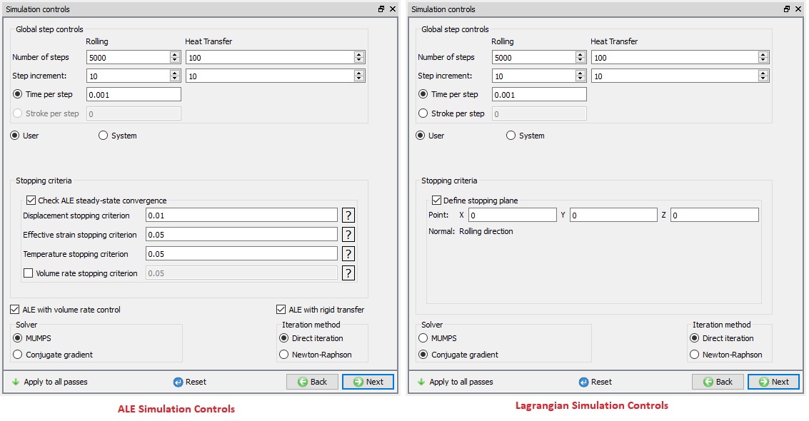
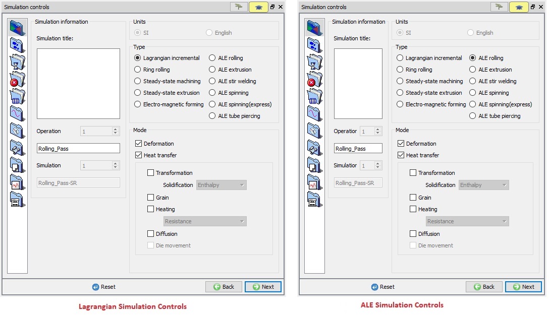
Simulation Controls
Simulation control settings can be defined at the Rolling Group level and apply those settings to all passes using ![]() . User can make changes to these settings for any specific pass at Pass level Simulation Controls, advanced settings are accessible using expert mode at Pass level. Simulation control settings for ALE and Lagrangian rolling types is shown in Fig. 43.1.45. “Global step controls” are similar for both ALE and Lagrangian, while the stopping criteria settings are different.
. User can make changes to these settings for any specific pass at Pass level Simulation Controls, advanced settings are accessible using expert mode at Pass level. Simulation control settings for ALE and Lagrangian rolling types is shown in Fig. 43.1.45. “Global step controls” are similar for both ALE and Lagrangian, while the stopping criteria settings are different.
Global step controls
Number of steps: Number of steps to be simulated during each Pass and HT can be defined at Rolling group level which will applied to all passes and HT operations of that Rolling group. If the simulation stops due to stopping criteria before completion of defined steps then next operation starting step will be continuation from previous operation.
Step increment: The step increment (STPINC) to save in the database controls the number of steps that the system will save in the database. When a simulation runs, every step must be computed, but does not necessarily need to be saved in the database. Storing more steps will preserve more information about the process, consequently it will require more storage space.
Time per Step: If time per step is specified, the time interval per step will be used. The die displacement per step will be the time step times the die velocity.
Stroke per Step: If stroke per step is specified, the primary die will move the specified amount in each time step. The total movement of the primary die will be the displacement per step multiplied by the total number of steps.
User: It will allow the users to specify their own step size. User should provide an appropriate step size to meet their stopping condition based on their number of steps.
System: It will automatically calculate the step size to meet their stopping condition based on their number of steps.
Stopping criteria
ALE Stopping criteria: ALE simulation can be automatically stopped once the steady state is reached with respect to diminishing gradients of the state variables and the geometry corrections reaching the exit section. This stopping criterion can be activated by turning on “Check ALE steady-state convergence” check box and defining the ALE Steady-State convergence settings.
Volume rate stopping criterion : Simulation will be stopped when volume rate ratio between entry and exit is within the stopping criteria.
ALE with volume rate control : When ALE with volume rate control is turned on, then simulation will try to use Volume rate constancy between exit and entry and try to minimize the difference between volume rate at entry and exit to improve the accuracy of the solution.
ALE with rigid transfer : When ALE with rigid transfer is turned on, then system will identify the rigid zones and deformation zones similar to RSE and nodes within rigid zone will not be updated which will decrease the time to reach convergence in general.
Lagrangian stopping criteria: Lagrangian rolling simulations can be automatically stopped once the billet passes through the last roll set center or at any plane along the roll pass direction as user desires. The stopping plane can be defined in “Stopping criteria” by specifying the co-ordinate on the stopping plane and direction will be rolling direction by default, which is set automatically, see Fig. 43.1.45. After all nodes of workpiece cross this defined point (imaginary plane) the simulation stops for that pass. These settings can be defined independently for each pass at Pass level, roll pass direction +X or -X can be selected based on rolls movement as shown in Fig. 43.1.45.
Solver : We can apply the solver settings for all passes of the rolling group as shown in Fig. 43.1.45. By default, “MUMPS” solver for ALE type rolling simulation and “Conjugate gradient” solver for Lagrangian type rolling simulation is selected.
Iteration method : User can select the iteration method as shown in Fig. 43.1.45. either Direct iteration or Newton-Raphson, which will be applied for all the passes of the rolling group.
Simulation Controls for GUIDED Mode
Apply to all passes: If user wants to overwrite the independent simulation controls with global simulation controls or apply changes in the global simulation controls to all passes then user can use Apply to all passes, as shown in Fig. 43.1.45. which will overwrite the simulation controls of all passes with global simulation controls. User can also define step controls and stopping criteria for each pass independently as shown in Fig. 43.1.46. The settings defined at pass level will have precedence over global simulation controls.

Simulation controls in GUIDED Mode (Operation level)
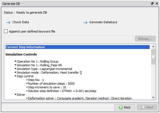
Generate DB
In Generate DB page, we can observe the Operation Simulation setup summary as shown in Fig. 43.1.47.
Check Data![]() : It checks the Data. If Data is correct, we can generate DB. But while checking Data if it gives any errors or warnings then it should be corrected before generating Database. Errors will not allow the database to be generated while warnings will allow the DB to be generated.
: It checks the Data. If Data is correct, we can generate DB. But while checking Data if it gives any errors or warnings then it should be corrected before generating Database. Errors will not allow the database to be generated while warnings will allow the DB to be generated.
Generate Database ![]() : By clicking on this button, it generates the Database for the setup. When user generates DB at Rolling Group level then the database is generated from the start of the rolling operation. (See Fig. 43.1.47. )
: By clicking on this button, it generates the Database for the setup. When user generates DB at Rolling Group level then the database is generated from the start of the rolling operation. (See Fig. 43.1.47. )
Append Key file : Any information that is not defined in the template but still applicable to the process can be loaded as .key file. This option is also useful in the cases where only few values needs to be changed then those values can be defined as .key file and store in specified path. When necessary only values in .key file can be changed and simulation can be resubmitted to study the effect of the change in parameters.
Generate DB page
Shape Rolling Pass Level
After completion of the global level data definition a Rolling Group level, user can select a Pass from the operation editor to make changes to the respective pass. As the user select the pass Stand table page is opened in Property editor space. User can add tables, add/ remove stands at pass level stand table, this stand table is also accessible from Pass table (see Fig. 43.1.48.). Remesh criteria and advanced settings using expert mode are accessible only at pass level. Operation tree at Roll Pass level for Lagrangian rolling and ALE rolling looks like as shown in Fig. 43.1.48.
In ALE and Lagrangian Rolling pass user can define or modify following data for respective objects,
Workpiece: Object type (Plastic/ Elasto-plastic type is preferred for shape rolling), Geometry, Mesh settings, Material, Boundary conditions, movement controls, initialize state variable values (temperature, strain… etc) and Built-in-flownet.
Rolls: Object type (Rigid/ Elastic type is preferred for shape rolling), Geometry, Mesh settings, Material, Boundary conditions and movement controls.
Pusher(Lagrangian Rolling type): Object type (Rigid type is preferred for shape rolling), Geometry, Mesh settings, Material, Boundary conditions and movement controls.
Table/ Guide (Lagrangian Rolling type): Object type (Rigid type is preferred for shape rolling), Geometry, Mesh settings, Material and Boundary conditions.
Apart from the above data user can perform schedule positioning between passes, modify inter-object data and simulation controls.
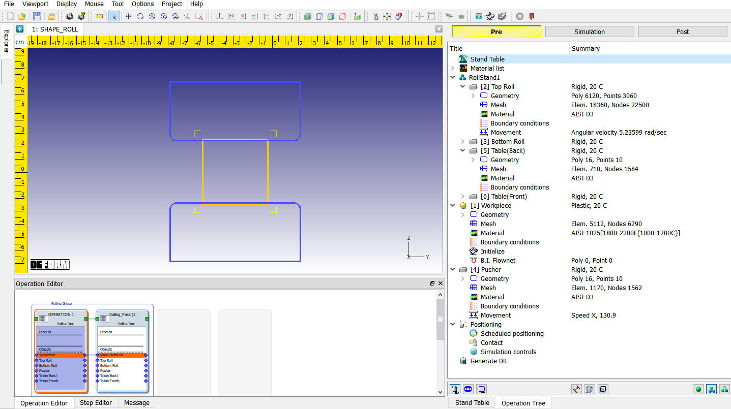
Rolling Pass level operation tree
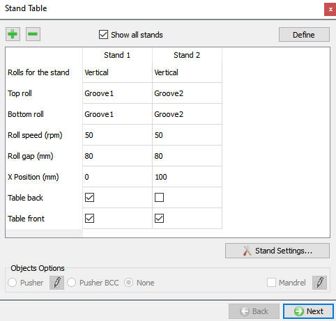
Stand Table
As the user opens Pass level for a Pass, “Stand Table” page is opened. User can add multiple stands if a pass is having more than one stand (see Fig. 43.1.49.), data for each stand can be defined using ![]() button (for more details on “Stand Settings” refer Stand Settings from Rolling Group level). Defining Roll set type, Rolls groove geometry, Roll speed and Roll gap in “Stand Table” is similar to Pass table.
button (for more details on “Stand Settings” refer Stand Settings from Rolling Group level). Defining Roll set type, Rolls groove geometry, Roll speed and Roll gap in “Stand Table” is similar to Pass table.
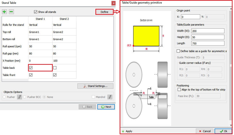
In Stand Table user have options to select whether to use table/guide in respective stand (see Fig. 43.1.49.), a stand can have “Table Front” (at exit end) and “Table Back” (at entry end) or only one of them. User can select any stand and Table (see Fig. 43.1.50.) to define its data using ![]() button at the top of stand table as shown in the Fig. 43.1.50., for more details on Table definition refer Table geometry.
button at the top of stand table as shown in the Fig. 43.1.50., for more details on Table definition refer Table geometry.
Stand table page (Operation level)
Defining table geometry from the Stand table page (Operation level)
Roll Stand Page
In this page it shows the Rolls data for the respective selected stand as shown in the Fig. 43.1.51., refer Stand settings from Roll Group level.
Roll stand 1 page (Operation level)
Roll Geometry page
In this page user can define or change the geometry settings which is generated in the 3D Setup page. The user is provided with both guided mode and expert mode geometry settings (as shown in Fig. 43.1.52. and Fig. 43.1.53.). For advanced geometry setting which are available in expert mode please refer to 3D geometry setting.
Roll geometry page in GUIDED Mode (Operation level)

Roll Geometry page in EXPERT Mode (Operation level)
####
Roll Mesh Page
In operation level we can generate the rolls mesh. When we visit the roll mesh page by default the Brick mesh type is select as shown in the Fig. 43.1.54. For more information please go through the 13.2. 3D Tet Mesh Generation and 13.3. 3D Brick Mesh Generation. Lagrangian Rolling type can be set up using both Brick and Tetrahedral mesh while ALE rolling type can be set only using Brick mesh.
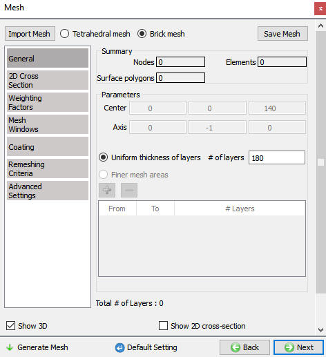
Roll Mesh page (Operation level)
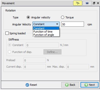
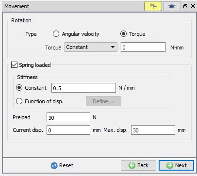
Roll Movement page
The Roll Movement can be defined in both Guided Mode and Expert Mode. Using guided mode user can define Roll movement as Angular velocity or Torque. The movement can be constant, function of time and function of angle as shown in Fig. 43.1.55.
A roll can be a spring loaded, in such case user can turn on Spring loaded check box and define Stiffness (can be constant or Function of displacement), Pre-load, Current displacement and Maximum Displacement as shown in Fig. 43.1.56.
If user wants to define any advanced movement controls, then it can be done using Expert mode settings as shown in Fig. 43.1.57. for more details on these settings please refer 15. Movement Controls Settings.
Roll Movement Controls in GUIDED Mode
Defining Spring loaded movement data in GUIDED Mode
Roll Movement Controls in EXPERT Mode
Table/Guide geometry page
User can use primitives to define the Table/ Guide geometry using ![]() button. When user clicks on
button. When user clicks on ![]() button, Table/Guide primitive definition window will be opened as shown in Fig. 43.1.58.
button, Table/Guide primitive definition window will be opened as shown in Fig. 43.1.58.
The user can define the Table/Guide parameters click on ![]() to generate table/guide. User can define Guide instead of table by turning on “Define table as guide for asymmetric shape rolling” check box as shown in Fig. 43.1.59.
to generate table/guide. User can define Guide instead of table by turning on “Define table as guide for asymmetric shape rolling” check box as shown in Fig. 43.1.59.
Origin point: It is Left bottom corner co-ordinate of the Table2D cross-section in case of table (see Fig. 43.1.58.) and inner Left Corner Radius center point in case of Guide (see Fig. 43.1.59.).
Table/ Guide Parameters: Width (W), Height (H) and Length of the Table / Guide can be defined here.
Guide Thickness (T): Thickness of the guide can be specified here.
Guide Corner Radius (if any): Guide corner radius can be specified here.
Positioning/ Pass Line: Table can be aligned with the roll by defining “Pass line (PL)” value after turning on “Align to the top of bottom roll for strip rolling” check box, see Fig. 43.1.58. The table will be moved down from the bottom roll top surface by the amount of Pass line value and then interference positioned in +X direction (for back table) / -X direction (for front table).
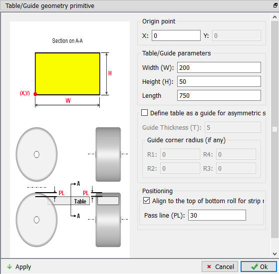
Table Geometry Primitive definition
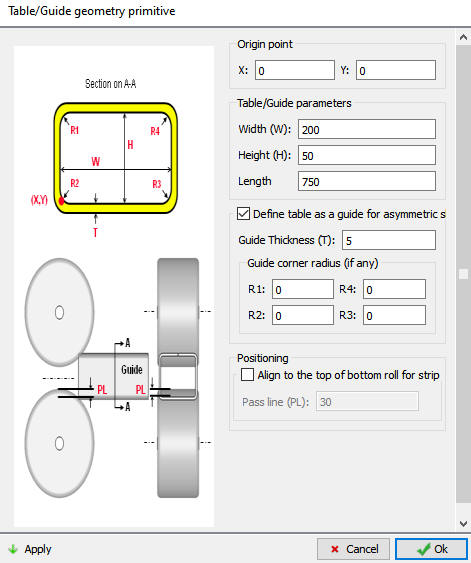
Guide Geometry Primitive definition
Workpiece Object page
The user can define the Object name, Temperature and object type (As shown in Fig. 43.1.60.). Plastic object type is selected by default, if user is interested to consider the effect of elastic properties then Elasto-plastic object type can be used.
For Lagrangian rolling type we can import the 3D Workpiece object using the ![]() ,
, ![]() options at the first pass. If the Workpiece object is imported from a file then the mesh settings will be as shown in Fig. 43.1.61. which is similar to the Forming operation mesh page.
options at the first pass. If the Workpiece object is imported from a file then the mesh settings will be as shown in Fig. 43.1.61. which is similar to the Forming operation mesh page.
Workpiece object page
Workpiece Mesh
The mesh settings of workpiece are similar to that of mesh settings in 3D setup page of Workpiece mesh generation at Rolling Group level, for details on the mesh settings refer 3D setup page. For Lagrangian setup if we import the Workpiece object or geometry, then we will get the general mesh page to generate the 3D workpiece mesh as shown in Fig. 43.1.61. For more information on this Mesh page, please go through the 13.2. 3D Tet Mesh Generation and 13.3. 3D Brick Mesh Generation.
Workpiece general mesh for imported object or geometry.
Force remeshing between Passes in ALE Rolling Type
From second Pass onwards, user can turn on “Force remeshing” check box in Workpiece mesh page and define the number of elements under “Meshing between passes” to generate new mesh before the start of the Pass simulation, see Fig. 43.1.62.
Entry cross section mesh from last operation:
The “Cross section at exit” or “Cross section at last roll contact” from last operation can be used as an entry 2D cross section for the current pass and generating 3D ALE mesh for subsequent rolling.

ALE Workpiece mesh page for second pass
Remeshing between Passes in Lagrangian Rolling type
In Lagrangian rolling type user can perform some additional actions apart from Force remeshing as shown in Fig. 43.1.63.
Force Remeshing: When this checkbox is turned on, then a new mesh will be generated with the specified number of elements before the pass simulation is started. For brick mesh, we will define the targeted 2D cross section mesh elements and for tetrahedral mesh, we will define the targeted elements for 3D workpiece mesh.
Axial Subdivision: By turning on this checkbox, the layer thickness in the new mesh along the rolling direction can be controlled using Axial subdivision value either by absolute length or aspect ratio.

Lagrangian Workpiece mesh page for second pass
Schedule to align workpiece to X- axis: If the workpiece axis moves away from the X- axis then the workpiece axis will be aligned with X-axis.
Boolean between passes
From second pass onwards, user can perform boolean operation to remove the extra material and control the regions of interest and the model size across multiple passes in a typical transient rolling process. In Lagrangian operation, as the stock or workpiece moves from one pass to another, its length increases. Mesh system used in the initial passes may soon become less effective to handle contact conditions in the subsequent passes due to the element stretching in the deforming region. Finer mesh from the start of the passes could be computationally more expensive. By using this Boolean operation, the user can select an area of interest in the rolling direction and periodically delete the workpiece that is stretched beyond this domain during rolling process. For example, if the end effects are not required to be modelled, user can trim the end regions after a set number of passes while maintaining good contact and material flow description with a model size that is computationally efficient. This can be done using the different options available as given below ( Fig. 43.1.64.).
S1 and S2 can be defined between 0 to 1, S1 represents front end while S2 represents rear end, 0 being the front end and 1 representing rear end. When S1 is “0”, the front-end mesh will be kept and when S2 is “1”, the rear end mesh will be kept.
For brick mesh type, new mesh will be generated based on the selection in Option tab,
0 – Keep the original mesh between S1 and S2
1 – Project the nodes at front end and rear end to a plane
2 – Smooth the axial location to sample the nodes.
3 – Specify axial locations to sample the nodes.
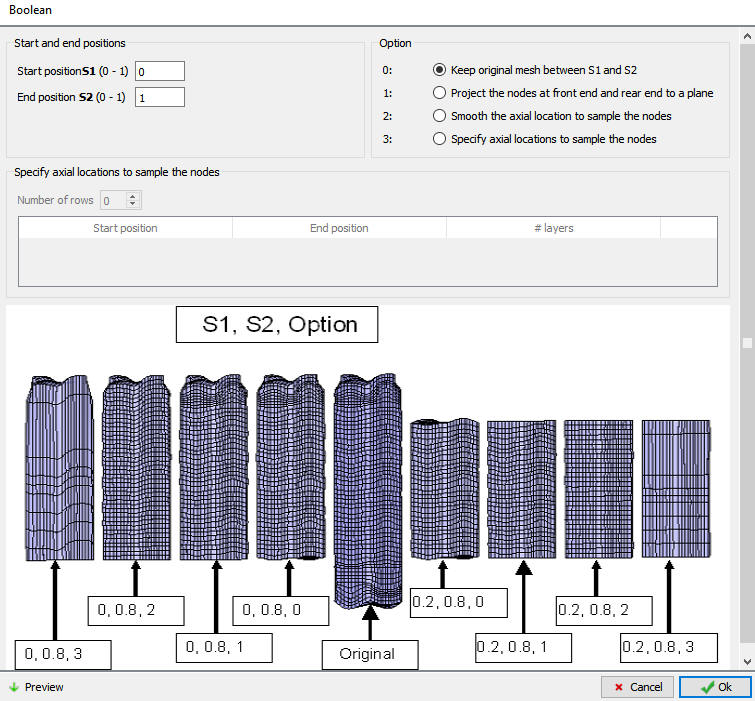
Boolean Between Passes Option for birck mesh
From v14, Boolean operation between the passes can be added even for the workpiece with Tet mesh ( Fig. 43.1.65.)..

Boolean Between Passes Option for tetrahedral mesh
Workpiece BCC
For ALE Rolling Type
The user can define the Symmetry, Deformation, Thermal and Diffusion BCC data depending on the process requirement. Beginning surface (entry end) and Free surface (exit end) must be defined for ALE Rolling type. By default, the Beginning surface and Free surface BCC data is assigned under deformation for ALE models see Fig. 43.1.66.
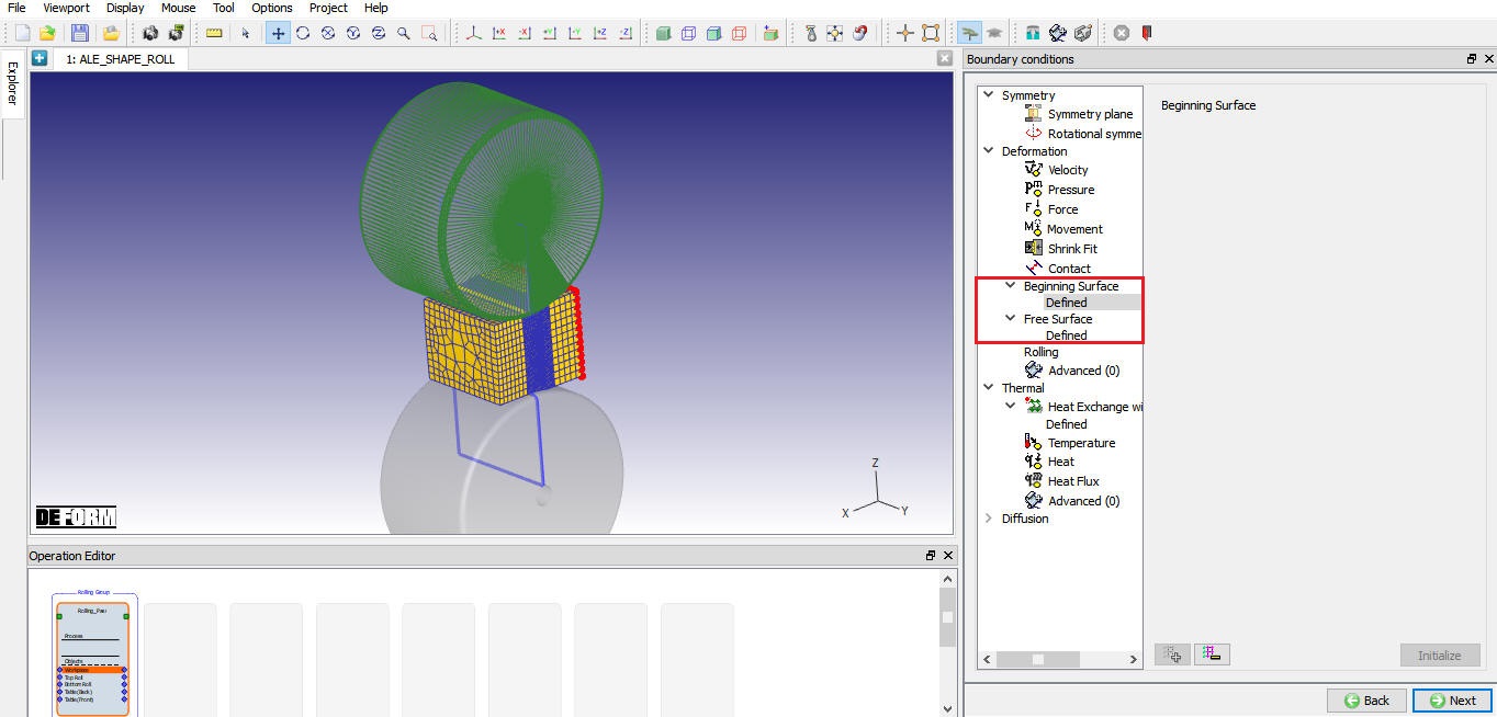
Beginning surface BCC for ALE Rolling type
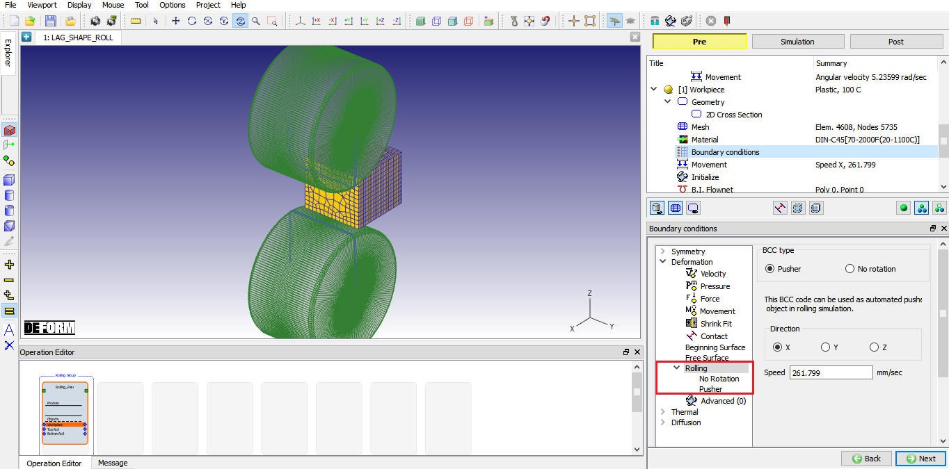
For Lagrangian Rolling Type
The user can define the Symmetry, Deformation, Thermal and Diffusion BCC data depending on the process requirement. For Lagrangian rolling type we have “Pusher” and “No rotation” options available under the Deformation -> Rolling as shown in Fig. 43.1. 67.
No Rotation BCC: This BCC is assigned when we select the Prevent twisting check box in the 3D Setup Page as shown in the Fig. 43.1.68. It prevents the rotation of workpiece in Lagrangian rolling so that it stays fixed to the x-axis through the rolling process.
Pusher BCC: This BCC is assigned when we define Pusher as BCC in 3D Setup Page as shown in the Fig. 43.1.69. Workpiece must have movement controls defined when this BCC is assigned. In Lagrangian rolling type the velocity is automatically calculated based on Rolls speed and assigned to workpiece, user can modify this value if required.
Rolling type BCC for Lagrangian Rolling type
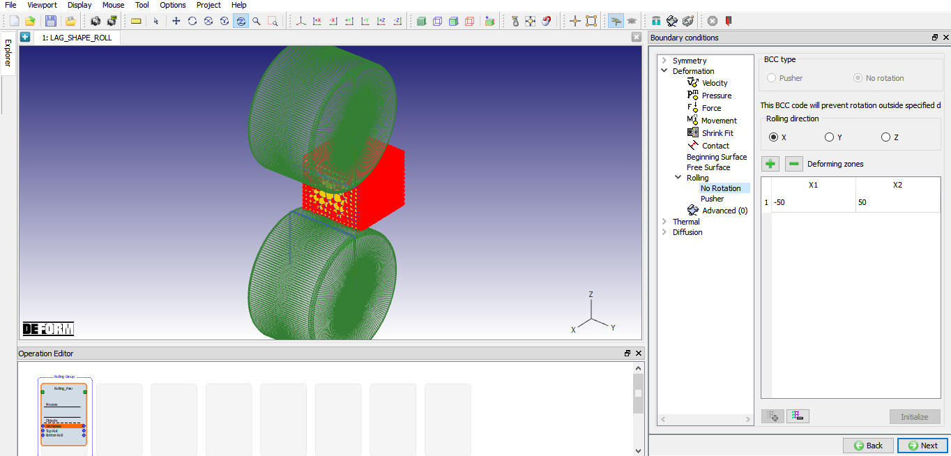
No Rotation type Rolling BCC
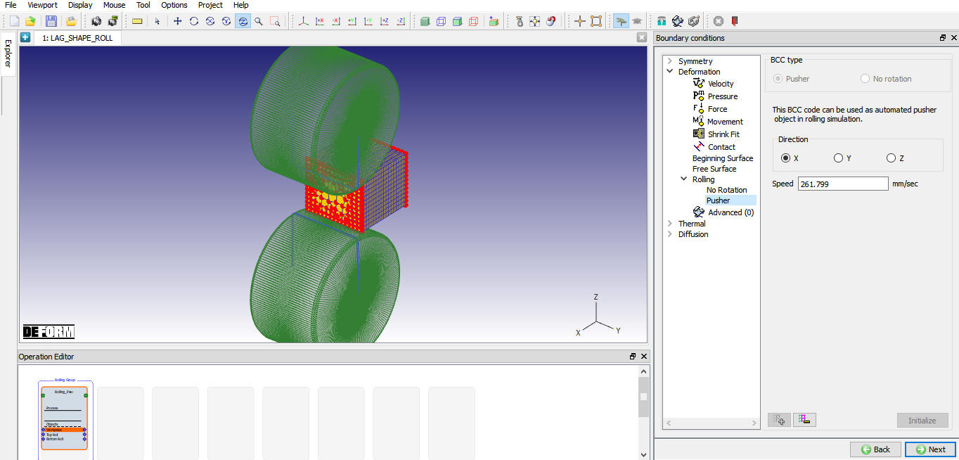
Pusher type Rolling BCC
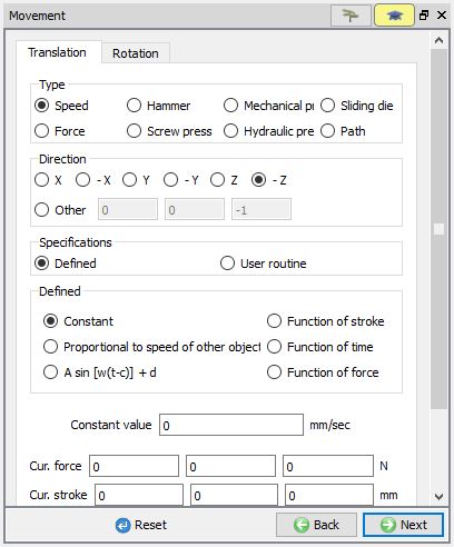
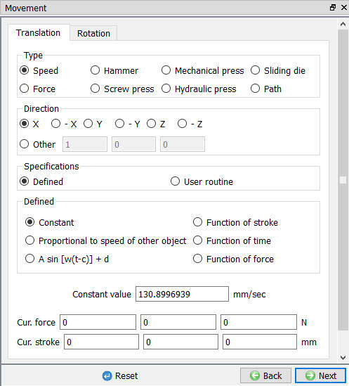
Workpiece Movement
In Lagrangian rolling type workpiece will have movement defined automatically if pusher is defined as BCC and user can modify this value based on Rolls speed and user can modify this value in movement page if required as shown in Fig. 43.1.70. No movement control definition is required for ALE rolling type.
Workpiece movement page for pusher BCC type
Workpiece Initialize
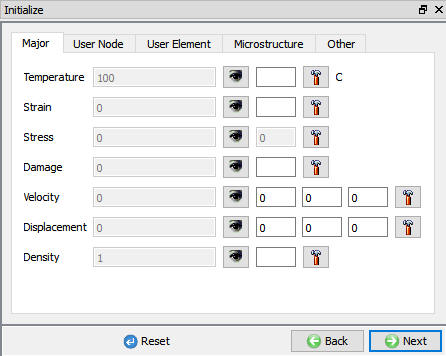
In Initialize window, few state variables that are commonly used such as temperature, strain, stress, damage, velocity, displacement, density and microstructure grain size and particle size are made available for initialization. In multiple pass rolling operation if user wants to initialize the temperature, strain or grain size then user can use this initialization page.
User can initialize the values for these state variables by defining in the field next to it and clicking on ![]() button. Fig. 43.1.71. shows various state variables that are available in Initialize window. Depending on the type of state variable, user can also initialize them from Node and Element data windows. For more information on how to initialize state variables in Node and Element windows, please refer 17.1. Node Data Window and 17.2. Element Data Window.
button. Fig. 43.1.71. shows various state variables that are available in Initialize window. Depending on the type of state variable, user can also initialize them from Node and Element data windows. For more information on how to initialize state variables in Node and Element windows, please refer 17.1. Node Data Window and 17.2. Element Data Window.
Initialize page
Workpiece Built-in Flownet
Multiple pass rolling setups normally generate DBs with large number of steps hence plotting a Flownet will take lot of time. User can overcome this issue by using Built-in-Flownet. When user uses Built-in-Flownet, the Flownet is calculated as the problem is simulated. For more information please refer Built in Flownet.
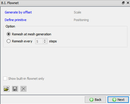
Built-in Flownet page
Positioning
When we click on Auto position ![]() button in 3D setup page/ Automatic Position
button in 3D setup page/ Automatic Position ![]() button in positioning page, all rolls, workpiece and pusher objects are positioned automatically. If user wants to modify any of these objects position, then user can use Position objects button in Positioning page. Various positioning options are available to position the objects as shown in Fig. 43.1.73., for more information on these options please refer 19. Object positioning.
button in positioning page, all rolls, workpiece and pusher objects are positioned automatically. If user wants to modify any of these objects position, then user can use Position objects button in Positioning page. Various positioning options are available to position the objects as shown in Fig. 43.1.73., for more information on these options please refer 19. Object positioning.
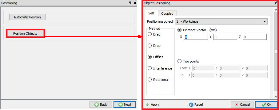
Object Positioning options
Scheduled Positioning
When user is not sure about the location of an object as in case of Read from DB objects, scheduled positioning will help to position the objects accurately. Schedule positioning allows the user to define the positioning for objects in Integrated Manufacturing Process setup for successive operations for which DB is not generated so that the objects are positioned before generation of DB while running simulation in Batch mode.
In Shape Rolling the schedule positioning is automatically defined by the system for 2nd Rolling Pass operation when we click on ![]() button in 3D Setup page as shown in the Fig. 43.1.74.
button in 3D Setup page as shown in the Fig. 43.1.74.
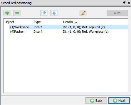
Scheduled positioning page
Contact
The user can define the contact between the Workpiece and other roll objects by defining the inter object relations as shown in Fig. 43.1.75. Global frictional value defined in Process page is automatically assigned and user can customize this value in Pass level contact page. User must define friction and Interface heat transfer co-efficient for non-isothermal rolling processes and friction value for isothermal rolling process.
System: By selecting this radio button, system assigns default inter-object relationships. Also, user can add the lubricants if necessary, by selecting Add New from pull down menu and clicking on ![]() button or user can load the required lubricants from the library for the simulation.
button or user can load the required lubricants from the library for the simulation.
User: By default, user radio button will be selected for shape rolling operation. User can add relationships by clicking on ![]() button as shown in Fig. 43.1.75. User can modify the value of each relation by selecting it and clicking on
button as shown in Fig. 43.1.75. User can modify the value of each relation by selecting it and clicking on ![]() button. User can use
button. User can use ![]() to assign same values to all relations. User can click on to calculate contact tolerance. User can click on
to assign same values to all relations. User can click on to calculate contact tolerance. User can click on ![]() to generate contact relation. User can turn on check box next to contact relation to define sticking contact. For more information please refer, 20.Inter-Object Relations.
to generate contact relation. User can turn on check box next to contact relation to define sticking contact. For more information please refer, 20.Inter-Object Relations.

Contact Page
Simulation Controls
The simulation controls settings at Pass level are similar to that of Rolling Group level, refer Simulation control in Rolling group. Simulation controls defined at Rolling Group level are applied to pass level automatically when ![]() button is clicked, user can modify these settings for each pass. In each pass level if user want to use the advanced simulation controls select the expert mode as shown in Fig. 43.1.76. For advanced simulation controls refer to 9. Simulation controls.
button is clicked, user can modify these settings for each pass. In each pass level if user want to use the advanced simulation controls select the expert mode as shown in Fig. 43.1.76. For advanced simulation controls refer to 9. Simulation controls.
Simulation Controls in Expert Mode (Operation level)
Generate DB
User can generate DB at pass level if it is a First pass or if previous passes simulation is completed in case of multi-pass rolling.
Related Topics: