Setting up 3D Fracture Element deactivation lab
2.1. Introduction
2.2. Creating a New problem
2.2.1. Adding 3D Forming operation
2.2.2. Import Sheet Blanking keyfile
2.2.3. Modifying the material properties
2.2.4. Selecting Fracture type
2.2.5. Generating Database
2.2.6. Running simulation
2.2.7. Post Processing
Introduction
Generally, fracture element deletion will be used for crack propagation study in DEFORM system. Due to the difficulty in brick remeshing, fracture element deletion currently does not support 3D brick mesh.
Fracture element deactivation is a new method to study crack propagation. It will deactivate an element instead of deleting it when its damage reaches the critical value of its material. It allows simulation to continue without remeshing or with less remeshing in forming processes. So, fracture element deactivation can support 3D brick mesh, 3D tetrahedral mesh and 2D mesh to predict crack onset & propagation. In this lab, we will demonstrate how to setup 3D Brick mesh model with Fracture element deactivation method..
Creating a New problem
On a Windows machine, go to the ![]() button, select DEFORM-v1x.xxx (.xxx indicates version number E.g. v14.0.2) and select DEFORM GUI Main v1x.x from the menu. The DEFORM GUI Main window will appear.
button, select DEFORM-v1x.xxx (.xxx indicates version number E.g. v14.0.2) and select DEFORM GUI Main v1x.x from the menu. The DEFORM GUI Main window will appear.
Create a new problem either by selecting File![]() **New Problem** or by clicking the New Problem
**New Problem** or by clicking the New Problem ![]() icon. The Problem Setup window will appear as shown in Fig.3DFRCL2.1. Select “ Integrated Manufacturing Process “ radio button and “SI “ radio button in Unit field. Define Problem Name as “3D_Fracture_Element_deactivation “ and make sure the “Show option dialog ” check box is turned on. Then click on
icon. The Problem Setup window will appear as shown in Fig.3DFRCL2.1. Select “ Integrated Manufacturing Process “ radio button and “SI “ radio button in Unit field. Define Problem Name as “3D_Fracture_Element_deactivation “ and make sure the “Show option dialog ” check box is turned on. Then click on ![]() button to open a new problem using the Deform Integrated Manufacturing Process.
button to open a new problem using the Deform Integrated Manufacturing Process.
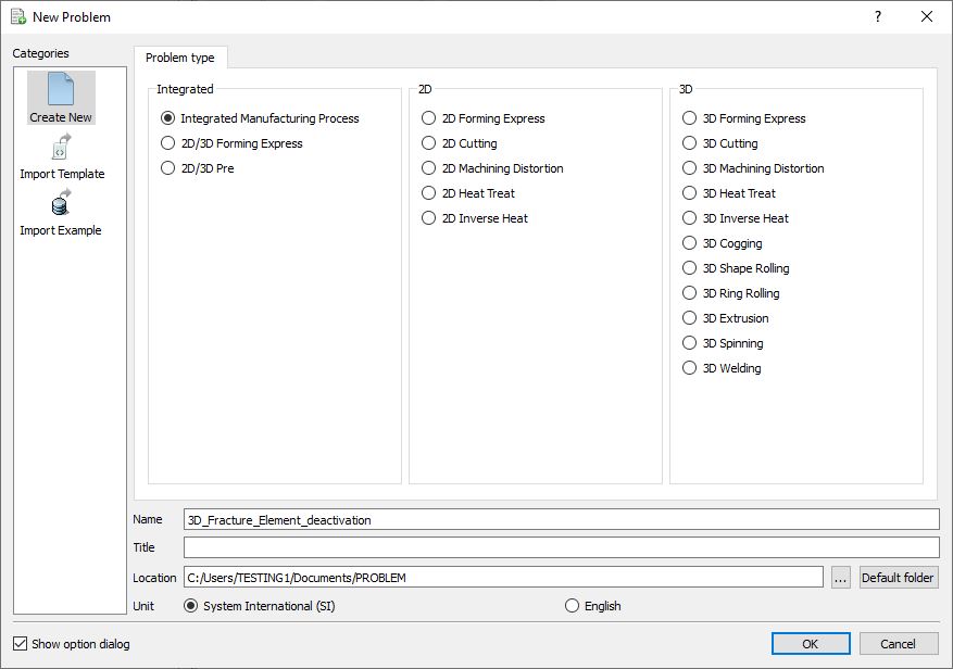
Problem type selection window
Multiple operation wizard will open with the New Project dialog as shown in Fig.3DFRCL2.2., at this point user will be prompted to specify a project name (system will create a separate folder with this project name) and title for this session. In this session, we will use “3**D _Fracture_Element_deactivation”** as the project name. 3D Forming operation can also be added in “New Project” dialog (see Fig.3DFRCL2.2.), but we will add 3D Forming operation in this lab from operations list in Explorer, so do not check “First operation” check box in “New Project” dialog. Click on ![]() to continue to open the operation.
to continue to open the operation.
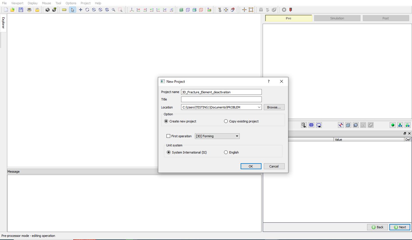
Project definition in New Project window from MO
Adding 3D Forming operation
Add one 3D Forming operation from the Explorer Operations list. Operation can be added by clicking on ![]() button adjacent to 3D Forming in Explorer or user can also add by drag and drop into the Operation Editor (See Fig.3DFRCL2.3.). As we add operation, Process page will be opened in the properties area.
button adjacent to 3D Forming in Explorer or user can also add by drag and drop into the Operation Editor (See Fig.3DFRCL2.3.). As we add operation, Process page will be opened in the properties area.
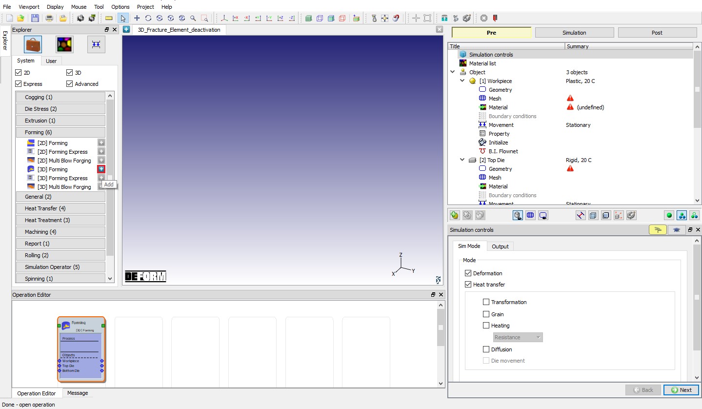
Adding 3D Forming Operation from explorer.
Import Sheet Blanking keyfile
Import “3D_SheetBlanking_Brick.KEY ” file from DEFORM Installation 3D\LABS folder using File![]() “Import Keyword ” option. Model setup is imported 3D Sheet blanking example keyfile is as shown in Fig.3DFRCL2.4.
“Import Keyword ” option. Model setup is imported 3D Sheet blanking example keyfile is as shown in Fig.3DFRCL2.4.
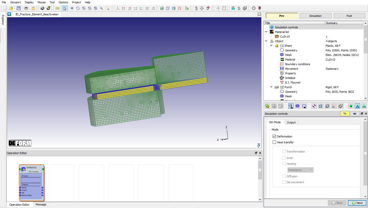
3D Sheet blanking example
Modifying the material properties
In operation tree, select CuZn15 under material list to display the material properties. From material properties, select the Miscellaneous properties tab. We can observe that Normalized C&L is selected as Fracture model, click on ![]() and observe the critical value defined. Critical value defined is 0.4 as shown in Fig.3DFRCL2.5. We can define the softening percentage of flow stress when Damage SV of an element reaches the material’s fracture model’s critical value. Define the Soften to as constant value 100 as shown in the Fig.3DFRCL2.6.
and observe the critical value defined. Critical value defined is 0.4 as shown in Fig.3DFRCL2.5. We can define the softening percentage of flow stress when Damage SV of an element reaches the material’s fracture model’s critical value. Define the Soften to as constant value 100 as shown in the Fig.3DFRCL2.6.
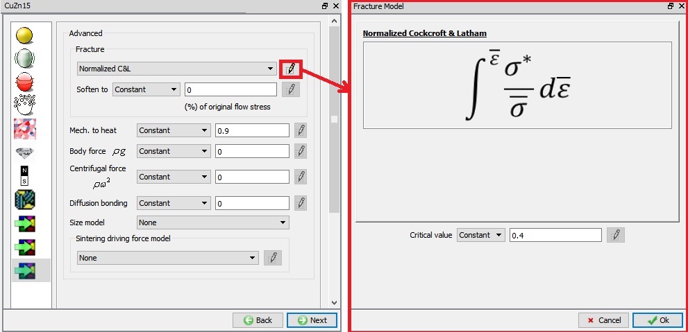
Critical value of Damage to initiate fracture
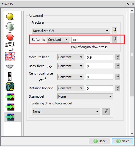
Defining softening % of flow stress
Selecting Fracture type
To select “Fracture element deactivation” type, go to Workpiece Object Properties page. Under Fracture tab, select “Fracture element deactivation ” type from Fracture pulldown menu as shown in Fig.3DFRCL2.7.
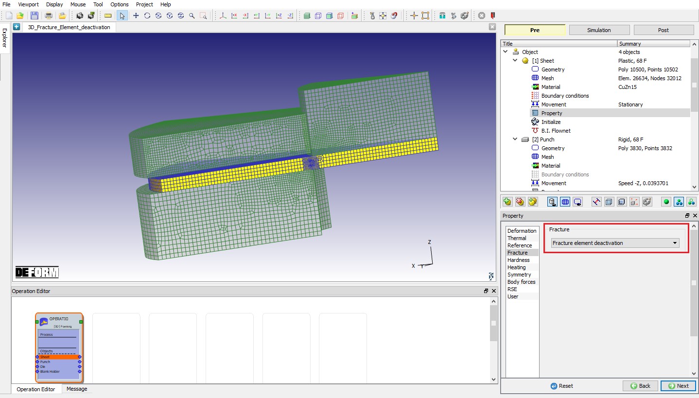
Selecting Fracture type
Generating Database
In operation tree, select “Generate DB ”, then click on ![]() button to have the program check to see if anything was missed in the problem setup. During the checking process, messages in the red colour signify data that needs to be fixed before a simulation can be run (such as when you forget to define any material data).
button to have the program check to see if anything was missed in the problem setup. During the checking process, messages in the red colour signify data that needs to be fixed before a simulation can be run (such as when you forget to define any material data).
Click on ![]() button to generate the database as shown in Fig.3DFRCL2.8.
button to generate the database as shown in Fig.3DFRCL2.8.
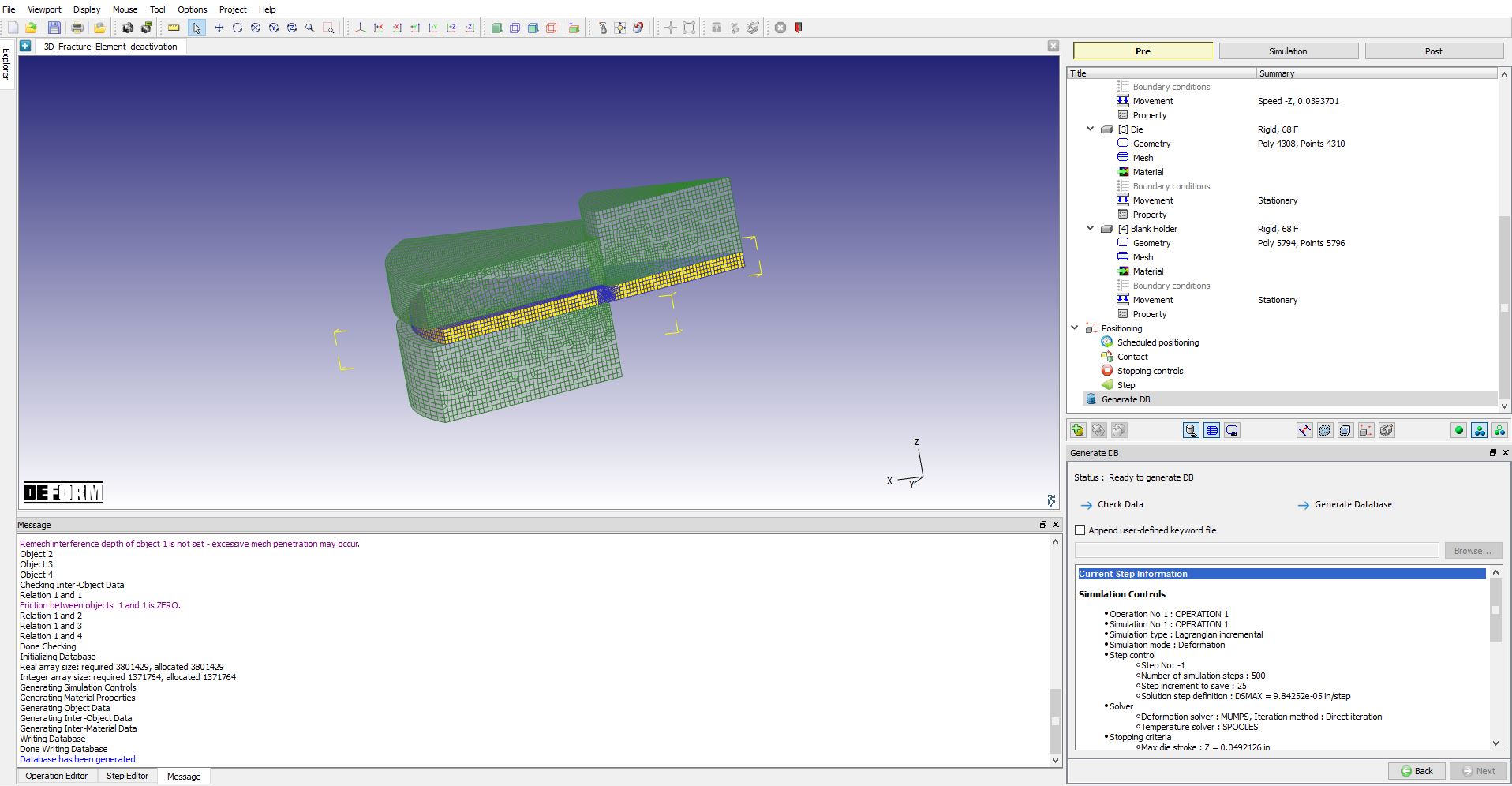
Generating Database
Running simulation
Once the database has been generated, switch to the Simulation mode by clicking on ![]() button above the operation tree. Click on the
button above the operation tree. Click on the ![]() action label to open the Run Options dialog as shown in Fig.3DFRCL2.9. Use the default ContinueRun option to select “Continue from the last step ” (from step -1) option and then select the Simulation mode as Interactive radio button.
action label to open the Run Options dialog as shown in Fig.3DFRCL2.9. Use the default ContinueRun option to select “Continue from the last step ” (from step -1) option and then select the Simulation mode as Interactive radio button.
To define MPI settings, click on ![]() button, Run Options window will expand and displays options to define MPI settings for simulation. We will define “MPI 3D” as 4 (or any number depending on your 3D MPI license) as shown in Fig.3DFRCL2.9. Then click on
button, Run Options window will expand and displays options to define MPI settings for simulation. We will define “MPI 3D” as 4 (or any number depending on your 3D MPI license) as shown in Fig.3DFRCL2.9. Then click on ![]() button to run the simulation.
button to run the simulation.
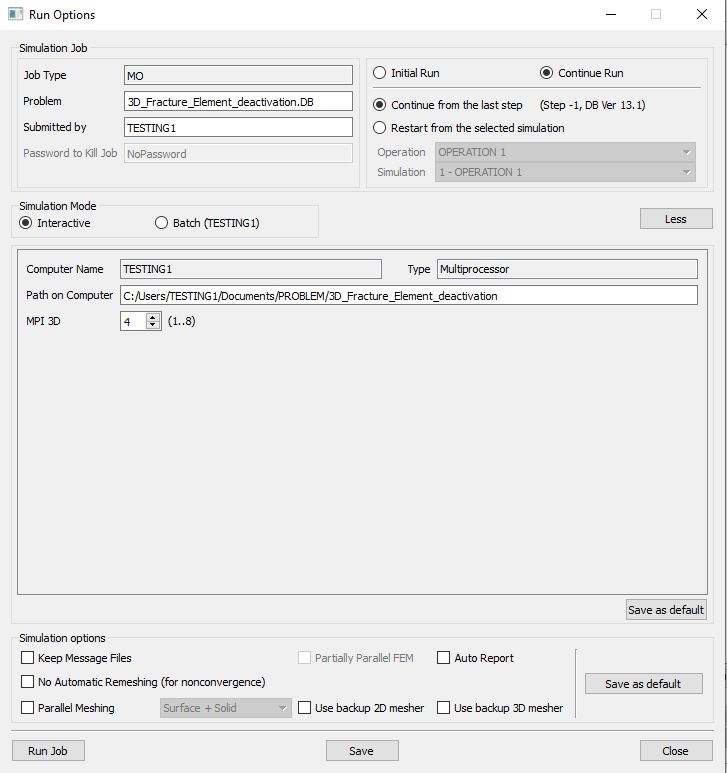
Run Options Popup
The progress of the simulation can be monitored as it is running by looking at the Simulation Message tab and Simulation Graphics from the Graphics display region in Simulation mode. If ![]() option is checked in Simulation Message tab, which is the default setting, the Message file will refresh automatically.
option is checked in Simulation Message tab, which is the default setting, the Message file will refresh automatically.
The Message file provides information about which simulation step the simulation is currently on and information dealing with how well the simulation is running as shown in Fig.3DFRCL2.10.
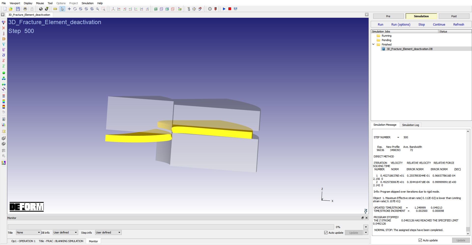
Simulation mode
Post Processing
After the simulation is completed, click on ![]() tab to visit MO post processor. Play the animation to see the crack onset & propagation from mesh, see Fig.3DFRCL2.11.
tab to visit MO post processor. Play the animation to see the crack onset & propagation from mesh, see Fig.3DFRCL2.11.
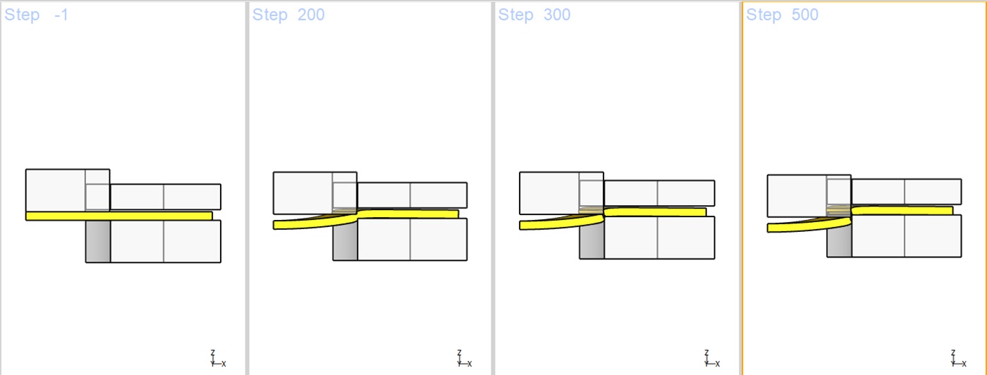
Onset and Propagation of crack
MO Post mode after simulation is completed
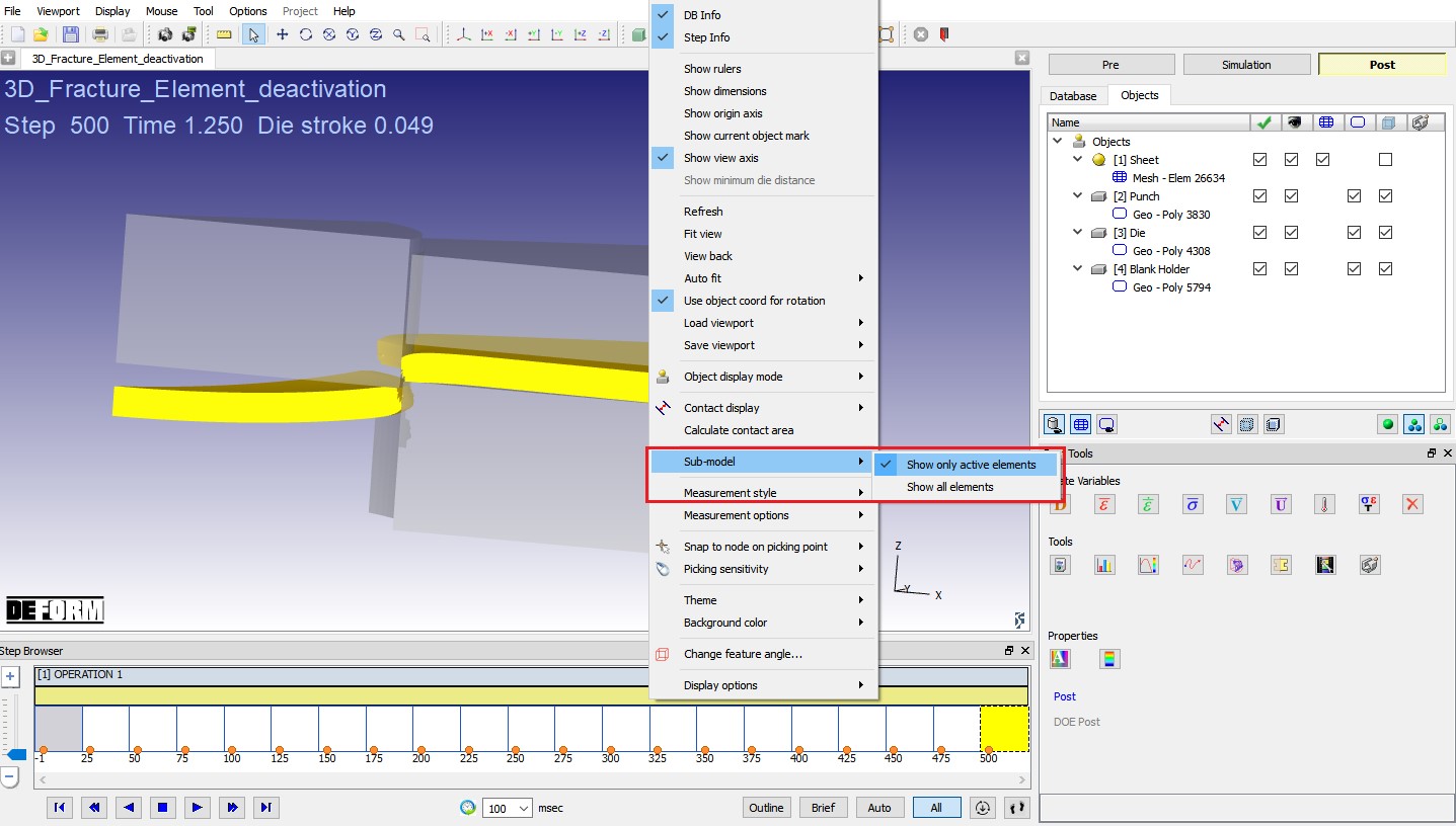
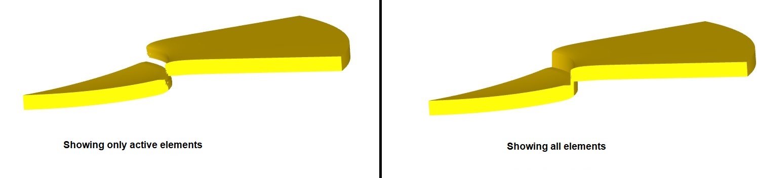
By default, only active elements of the model will be displayed. To view all the elements of the model, right click in Display area ![]() select “Sub-model ” from RMB popup menu
select “Sub-model ” from RMB popup menu ![]() select “Show all elements ” option ( Fig.3DFRCL2.12.) to see all elements of workpiece as shown in Fig. 3DFRCL1.13.
select “Show all elements ” option ( Fig.3DFRCL2.12.) to see all elements of workpiece as shown in Fig. 3DFRCL1.13.
Sub model options workpiece display
Click on State variable ![]() icon, select All button and Under Additive manufacturing menu plot “Element density ” variable. We can observe that the element density is 0 for deactivated elements and element density of other elements is 1. Display will be more clear using ‘Elemental’ display type, so select “Elemental ” display type as shown in Fig.3DFRCL2.14.
icon, select All button and Under Additive manufacturing menu plot “Element density ” variable. We can observe that the element density is 0 for deactivated elements and element density of other elements is 1. Display will be more clear using ‘Elemental’ display type, so select “Elemental ” display type as shown in Fig.3DFRCL2.14.
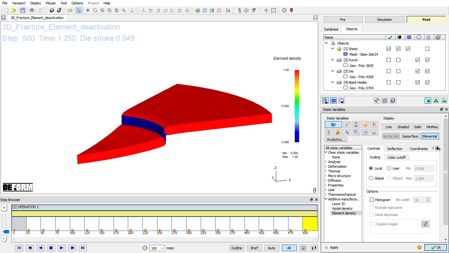
Element density state variable plot with Elemental display