2D Cartridge case drawing lab
Problem Summary:
In this lab, we will be demonstrating about how to use Integrated Manufacturing Process UI (MO) to setup multiple stages of forming process in batch mode. We will be setting up a multi-stage extrusion process to simulate cartridge case forming using [2D]Forming operation from Integrated Manufacturing Process UI. The process involves three stages of extrusion with annealing in between each stage for strain relief.
We will be setting up all 3 stations at a time in batch mode, Workpiece will be transferred to all operations while changing dies for station 2 and station3. We will be simulating only forming process in this lab and not annealing process, instead we will initialize the strain, damage and velocity of the workpiece in successive forming operations. The dies will be positioned using schedule positioning so that objects are positioned during DB generation. The contact generation also will be scheduled so that the contacts between objects will be generated during DB generation.
1. Creating New Problem and Adding Operations
1.2. Adding operations to Operation Editor
2.1. Select Geometry Type and Simulation Controls
2.8. Defining Scheduled positioning
2.9. Defining contact conditions
3.1. Select Geometry Type and Simulation modes
3.7. Defining Contact conditions and scheduling contact generation for Station2
3.8.Stopping controls for Station2
3.9. Step Controls for Station2
4.1. Select Geometry Type and Simulation modes
4.7. Defining Contact Conditions and scheduling contact generation for Station3
4.8. Stopping controls for Station3
4.9. Step Controls for Station3
Creating New problem and Adding Operations
Creating a New problem
On a Windows machine , press ![]() button, select DEFORM-v1x.xxx (.xxx indicates version number E.g. v14.0.2) and select DEFORM GUI Main vxx.xx from the menu. The DEFORM GUI Main window will appear.
button, select DEFORM-v1x.xxx (.xxx indicates version number E.g. v14.0.2) and select DEFORM GUI Main vxx.xx from the menu. The DEFORM GUI Main window will appear.
Create a new problem either by selecting File![]() **New Problem** or by clicking the New Problem
**New Problem** or by clicking the New Problem ![]() icon. The Problem Setup window will appear. Select “ Integrated Manufacturing Process “ radio button and unit system as “English “ using radio button. Define Problem Name as “Cartridge_Case_Lab “ and make sure the “Show option dialog ” check box is turned on (if we do not turn on the “Show option dialog ” check box, then we will not get the New Project dialog in MO UI). Click on
icon. The Problem Setup window will appear. Select “ Integrated Manufacturing Process “ radio button and unit system as “English “ using radio button. Define Problem Name as “Cartridge_Case_Lab “ and make sure the “Show option dialog ” check box is turned on (if we do not turn on the “Show option dialog ” check box, then we will not get the New Project dialog in MO UI). Click on ![]() button to close the New Problem dialog and open the project in Integrated Manufacturing Process UI.
button to close the New Problem dialog and open the project in Integrated Manufacturing Process UI.
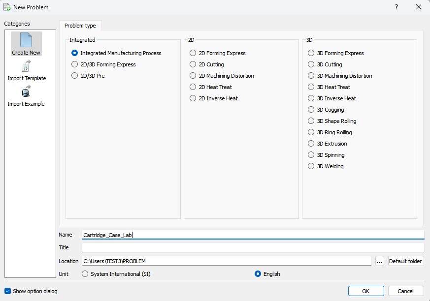
New problem dialog
Adding operations to Operation Editor
Multiple Operation wizard will open the new project. Add three 2d forming operations from Operations Explorer list clicking ![]() button.
button.
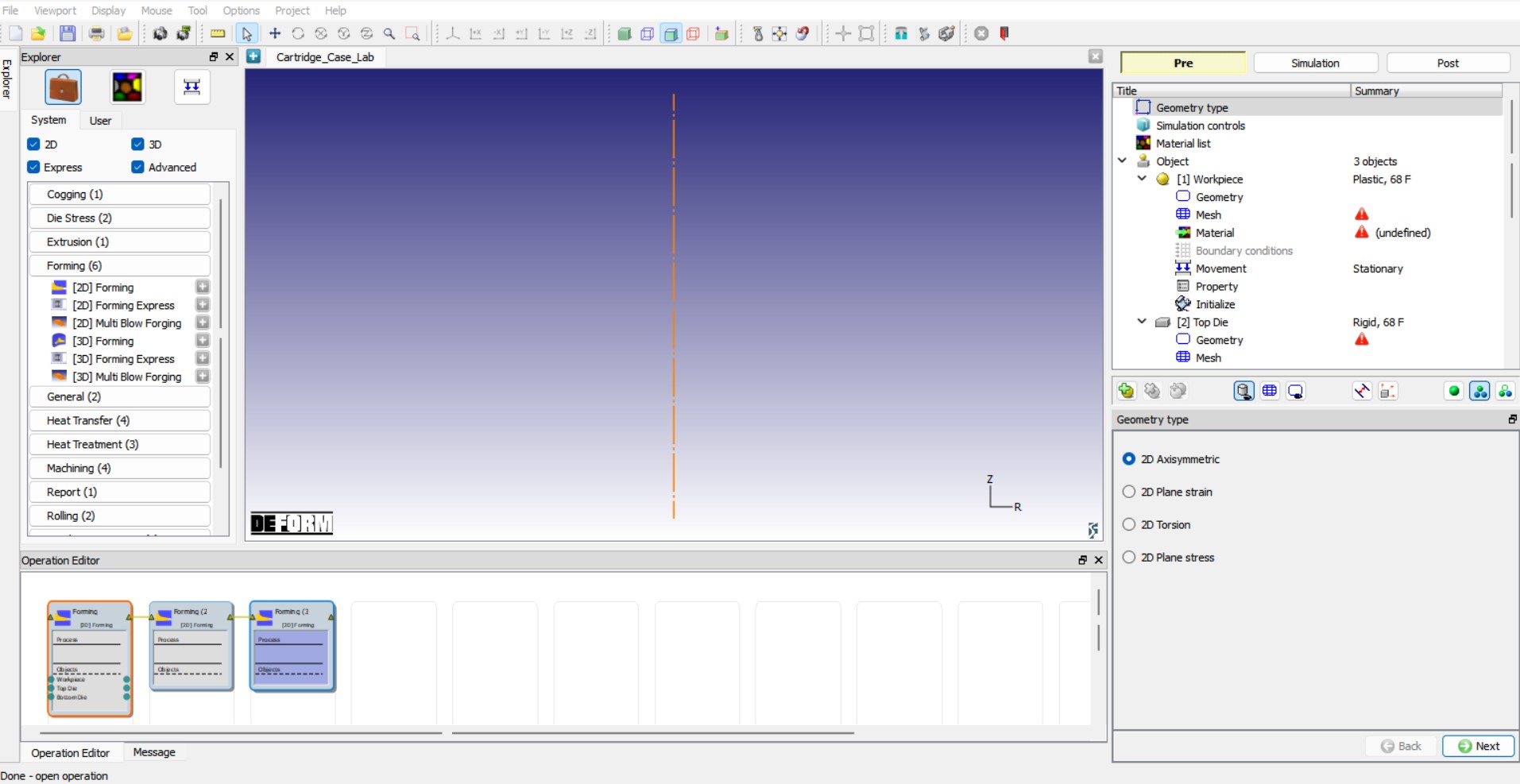
Adding operations
Setting up Station1:
Select first forming operation and change the operation name to “Station1 “ by double clicking on Operation name in Operation Editor window and press Enter in Keyboard.
Select Geometry Type and Simulation modes
Select the 2D Axisymmetric radio button in geometry type window as show in Fig. 2DCCDL1.3. and click ![]() to continue to Simulation controls page. In Simulation controls page, uncheck the Heat transfer mode check box as shown in Fig. 2DCCDL1.4. and click
to continue to Simulation controls page. In Simulation controls page, uncheck the Heat transfer mode check box as shown in Fig. 2DCCDL1.4. and click ![]() .
.
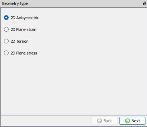
Geometry type selection
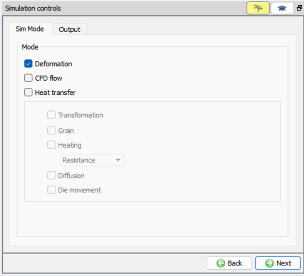
Simulation controls page
Material List
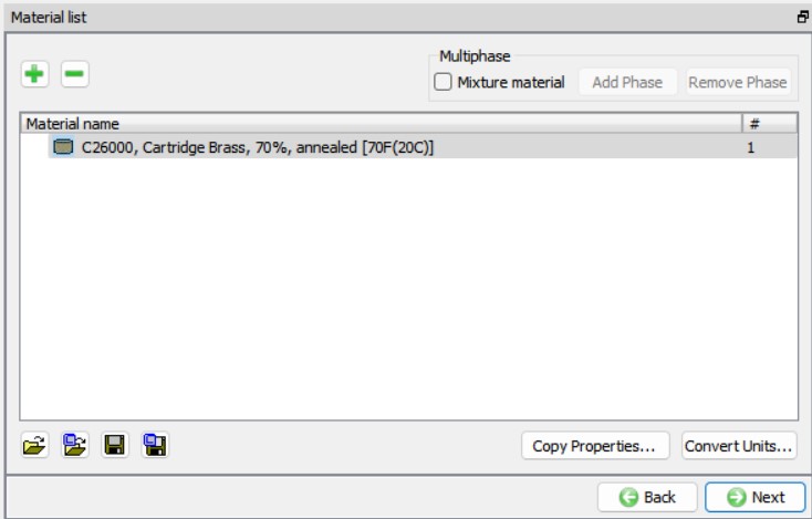
Once the geometry type an simulation modes are set, we will load the materials required for this setup. Using ![]() button in Material list page, import “C26000, Cartridge Brass, 70%, annealed [70F(20C)] “ material keyword from /2D/LABS/Cartridge_Lab folder, see Fig. 2DCCDL1.5. Click
button in Material list page, import “C26000, Cartridge Brass, 70%, annealed [70F(20C)] “ material keyword from /2D/LABS/Cartridge_Lab folder, see Fig. 2DCCDL1.5. Click ![]() to Object page.
to Object page.
Material List
Objects
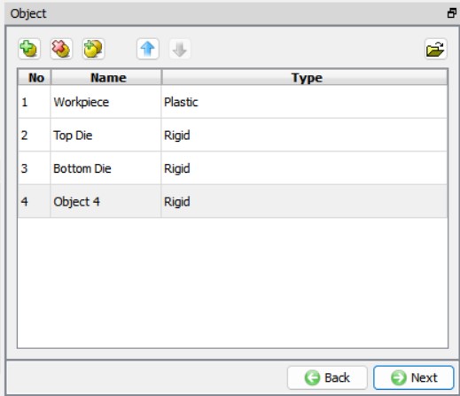
We need four objects, Workpiece, Die Punch and Ejector to model for this setup. By default, three objects are added to the object list, we will add one more by clicking on![]() button. The objects will be renamed suitably as we progress through the setup. Click
button. The objects will be renamed suitably as we progress through the setup. Click ![]() to Workpiece page.
to Workpiece page.
Objects list page
Workpiece
Workpiece object type definition
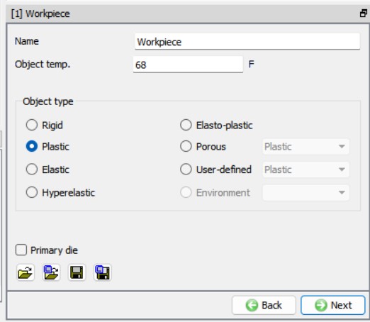
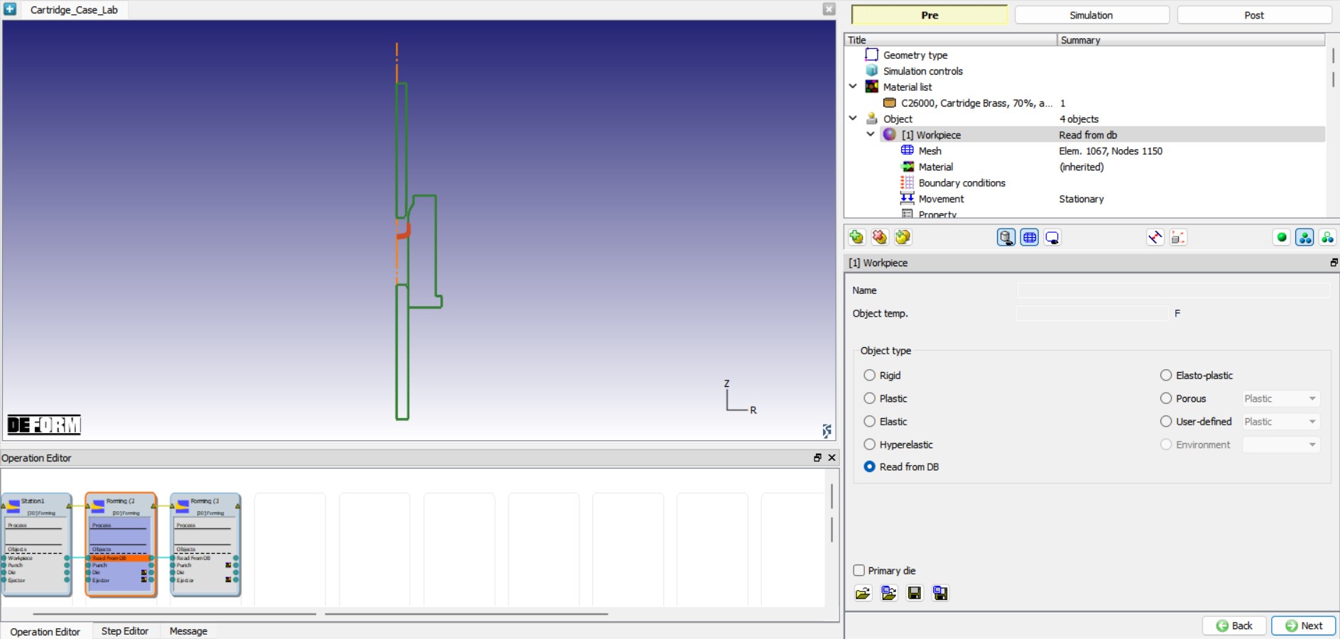
Keep the default Object name as “Workpiece “, Object Type as Plastic and it’s Temperature as 68 °F as shown in Fig. 2DCCDL1.7. Click ![]() to Geometry page to define Workpiece geometry.
to Geometry page to define Workpiece geometry.
Workpiece object page
Defining Workpiece Geometry
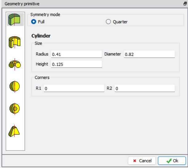
We will define workpiece geometry using primitives. From the Workpiece’s geometry page, click on ![]() , select Solid cylinder and define Diameter as 0.82 “ and Height as 0.125 “, see Fig. 2DCCDL1.8. Click on
, select Solid cylinder and define Diameter as 0.82 “ and Height as 0.125 “, see Fig. 2DCCDL1.8. Click on ![]() button in the Primitive window to close the window and click
button in the Primitive window to close the window and click ![]() to navigate to Workpiece Mesh page.
to navigate to Workpiece Mesh page.
Defining Workpiece geometry
Generating mesh for Workpiece
In Mesh page, click on ![]() to change to expert mode so that we can have access to various options to control mesh. Define the Target number of elements as 1000 , Thickness elements as 4 and Sizeratio as 3 , click the
to change to expert mode so that we can have access to various options to control mesh. Define the Target number of elements as 1000 , Thickness elements as 4 and Sizeratio as 3 , click the ![]() button to generate the mesh for workpiece, see Fig. 2DCCDL1.9. Click
button to generate the mesh for workpiece, see Fig. 2DCCDL1.9. Click ![]() button to Material page.
button to Material page.
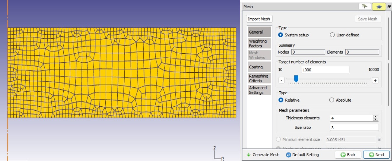
Mesh settings for Workpiece
Assigning material to Workpiece
Select the “C26000, Cartridge Brass, 70%, annealed [70F(20C)] “ in the material window to assign the material to the Workpiece, see Fig. 2DCCDL1.10. Click ![]() button to move to Workpiece Boundary conditions page.
button to move to Workpiece Boundary conditions page.
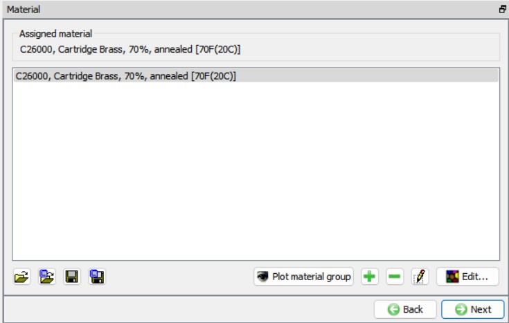
Assigning material to Workpiece
Boundary conditions for Workpiece
For Axi-symmetric setup by default, velocity in x-direction will be fixed for all the nodes along the axis, we can observe the same in the BCC page for the Workpiece, see Fig. 2DCCDL1.11. We do not need any additional BCC, hence click ![]() button to navigate to Workpiece Properties page.
button to navigate to Workpiece Properties page.
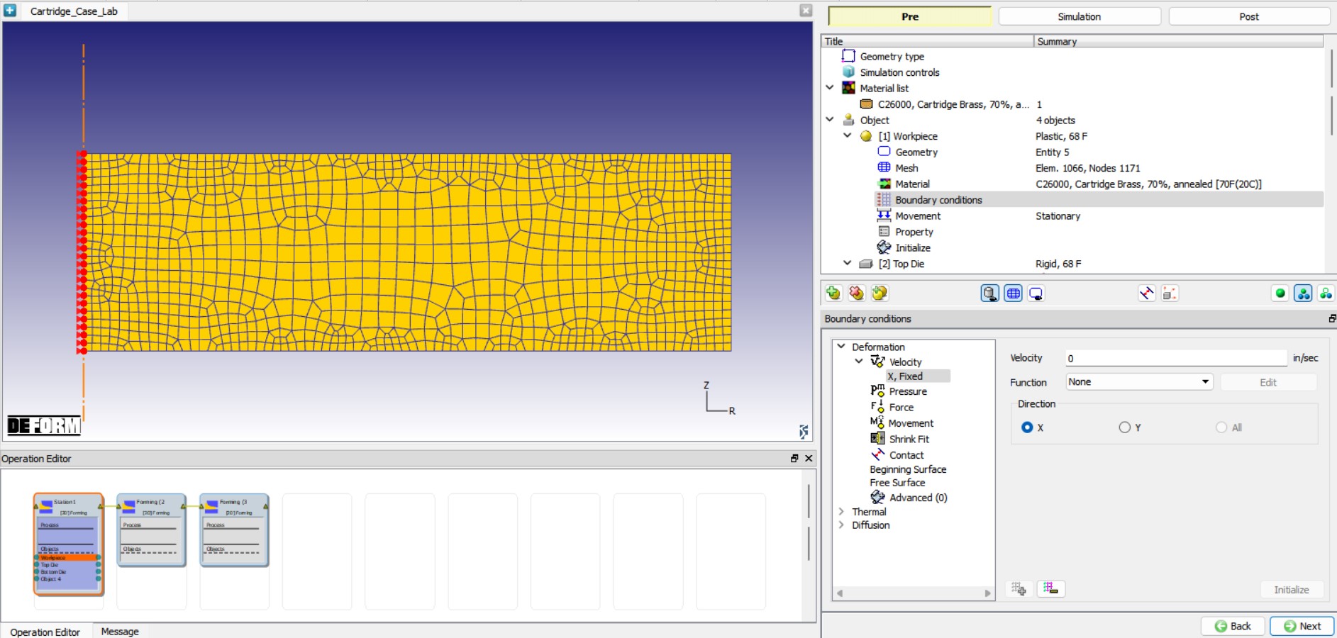
Velocity BCC for Workpiece
Setting Limiting strain rate value for Workpiece
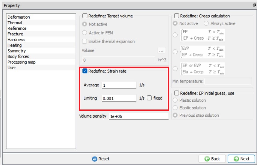
In Workpiece Properties page, we will modify the Limiting strain rate value to 0.001 from Strain rate tab to capturing the strains more accurately at lower strain rates, see Fig. 2DCCDL1.12. As we do not need to define anything else for Workpiece we will click ![]() button until we reach Top Die object page or select Punch from Operation tree.
button until we reach Top Die object page or select Punch from Operation tree.
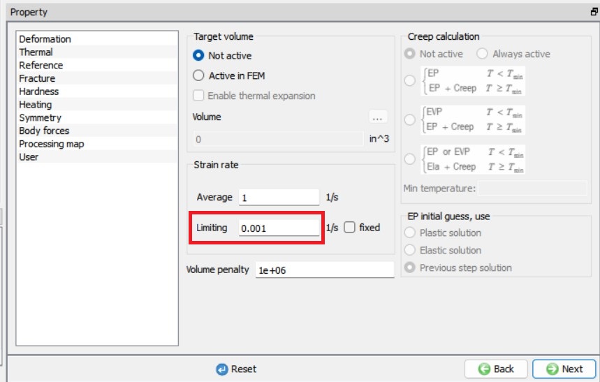
Setting Limiting strain rate value for Workpiece.
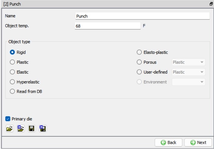
Punch
Punch object type definition
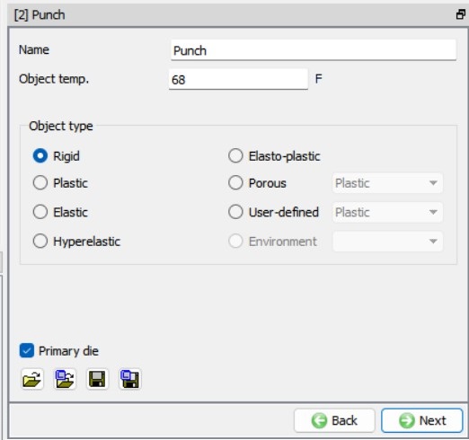
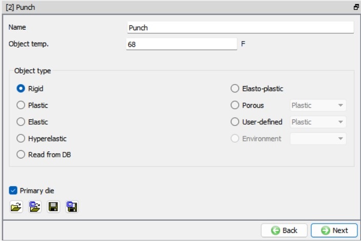
Change the object name to “Punch “, keep the Object type as Rigid and the Temperature as 68 °F. Make sure that the Primary die check box is turned on as this is a moving object and the step controls and stopping controls will be applied to this object, see Fig. 2DCCDL1.13. Click ![]() to Punch Geometry page.
to Punch Geometry page.
Punch object definition
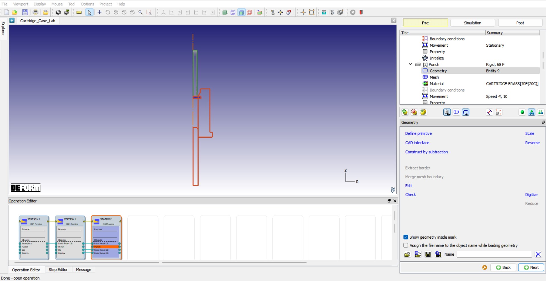
Punch Geometry Definition
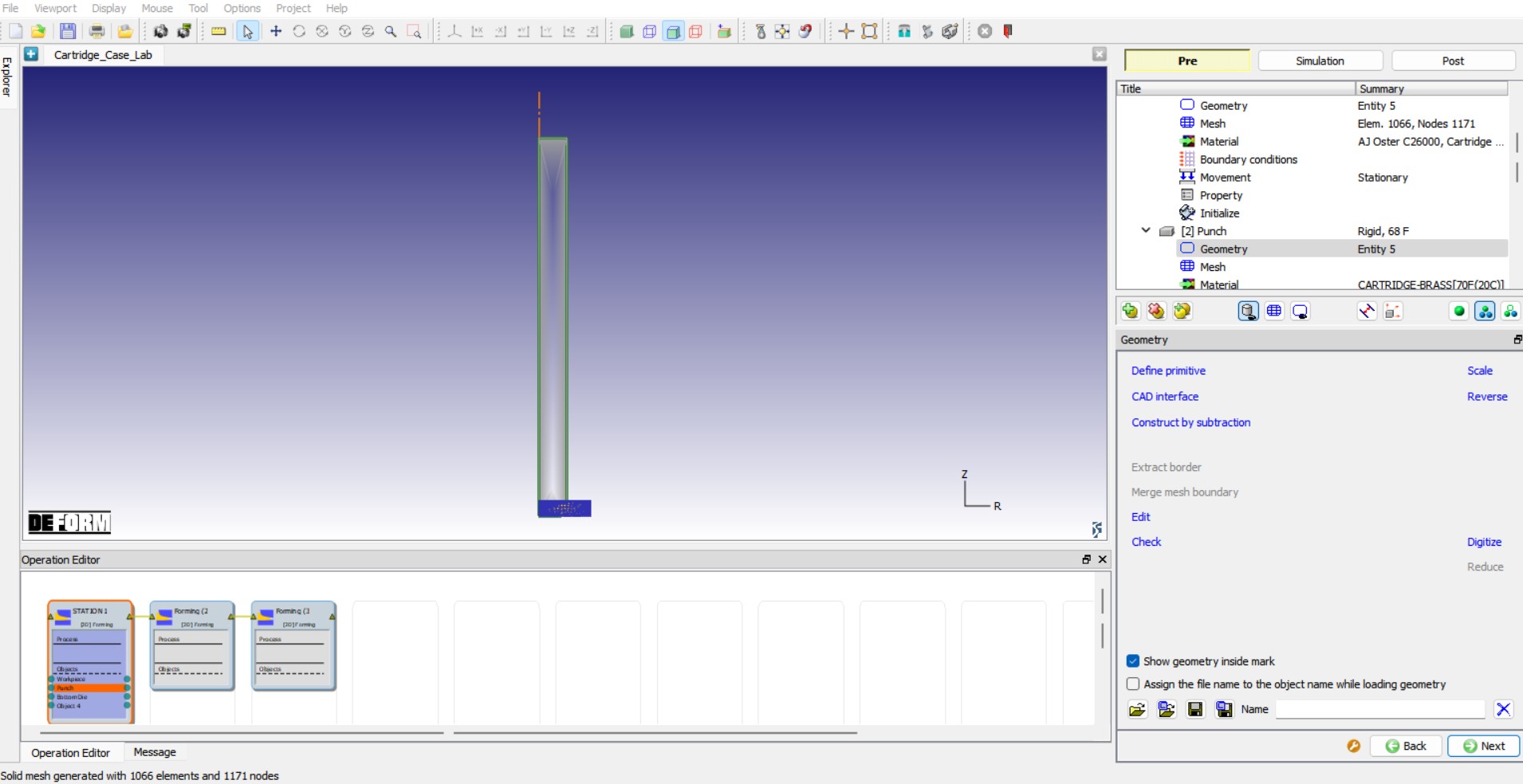
We will load the geometry for the Punch from a file stored in \2D\LABS\Cartridge_Lab directory. Click the ![]() (Load geometry from a file) button and import the file “Punch.geo ” by browsing the geometry file path located in DEFORM installation folder /2D/LABS/Cartridge_Lab directory, see Fig. 2DCCDL1.14. Check the geometry using
(Load geometry from a file) button and import the file “Punch.geo ” by browsing the geometry file path located in DEFORM installation folder /2D/LABS/Cartridge_Lab directory, see Fig. 2DCCDL1.14. Check the geometry using ![]() option to make sure the geometry is OK. The imported geometry should not have any issues. After defining the geometry for the Punch, we will use
option to make sure the geometry is OK. The imported geometry should not have any issues. After defining the geometry for the Punch, we will use ![]() button to navigate until Movement page. We will not generate mesh for the Punch as the object type is Rigid and we do not intend to calculate temperature distribution.
button to navigate until Movement page. We will not generate mesh for the Punch as the object type is Rigid and we do not intend to calculate temperature distribution.
Loading Punch geometry
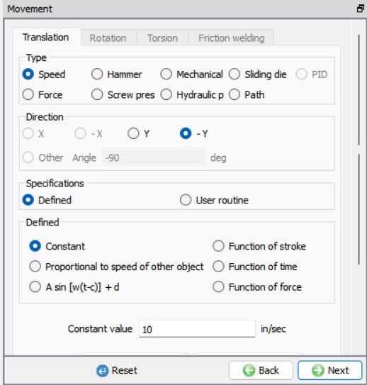
Defining Movement for Punch
The default mode for Punch movement is Constant speed. Input a value of 10 in/sec for the Constant value and confirm that the Direction is -Y , see Fig. 2DCCDL1.15. As we do not need to define anything else for Punch, we will click ![]() button until we reach Bottom Die object.
button until we reach Bottom Die object.
Movement controls for Punch
Die
Die object type definition
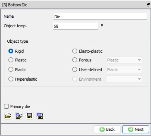
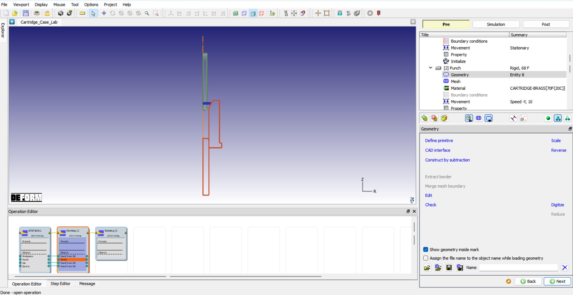
Change the object name to “Die “, keep the Object type as Rigid and the Temperature as 68 ° F, see Fig. 2DCCDL1.16. Click ![]() to Die Geometry page.
to Die Geometry page.
Die Object page
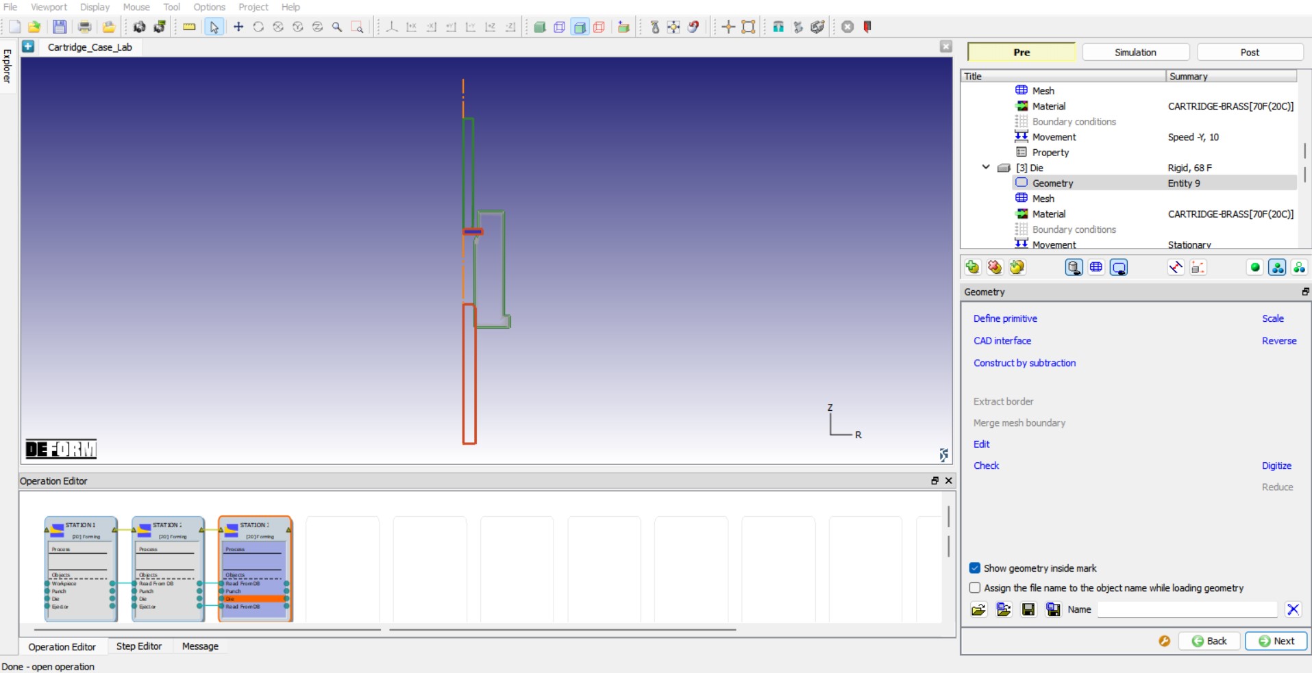
Die Geometry
For Die geometry, we will import the file “Die.geo ” by browsing the geometry file path located in DEFORM installation folder \2D\LABS\Cartridge_Lab directory using the ![]() (Load geometry from a file) button in Geometry page, see Fig. 2DCCDL1.17. Check the geometry using
(Load geometry from a file) button in Geometry page, see Fig. 2DCCDL1.17. Check the geometry using ![]() option to make sure the geometry is OK. We do not need to define mesh or movement controls for Die as the Die is a rigid object, stationary and we are not calculating temperature distribution over the Die, we will click
option to make sure the geometry is OK. We do not need to define mesh or movement controls for Die as the Die is a rigid object, stationary and we are not calculating temperature distribution over the Die, we will click ![]() button until we reach Object 4 page.
button until we reach Object 4 page.
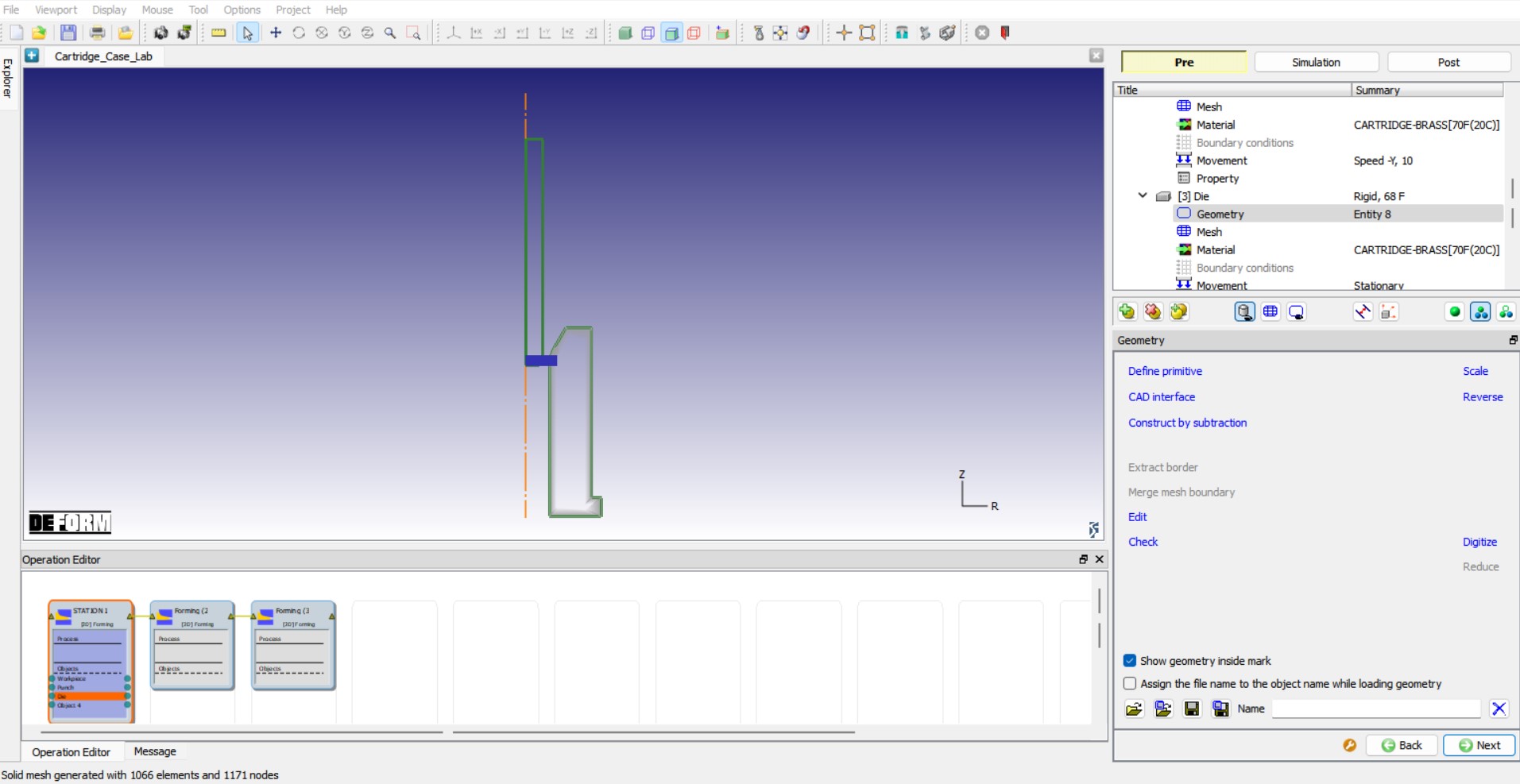
Loading Die geometry
Ejector
Ejector object type definition
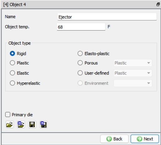
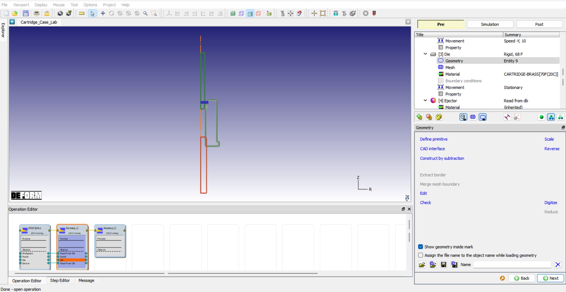
Change the object name from Object 4 to “Ejector “, keep the Object type as Rigid and the Temperature as 68 ° F, see Fig. 2DCCDL1.18. Click ![]() to Ejector Geometry page.
to Ejector Geometry page.
Ejector object page
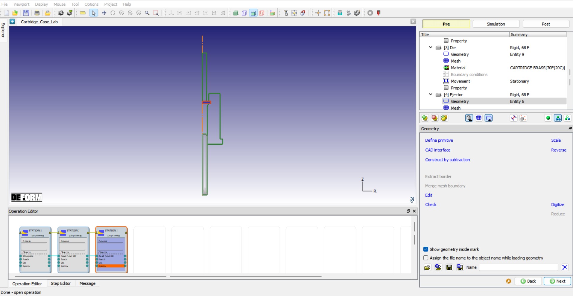
Defining Ejector Geometry
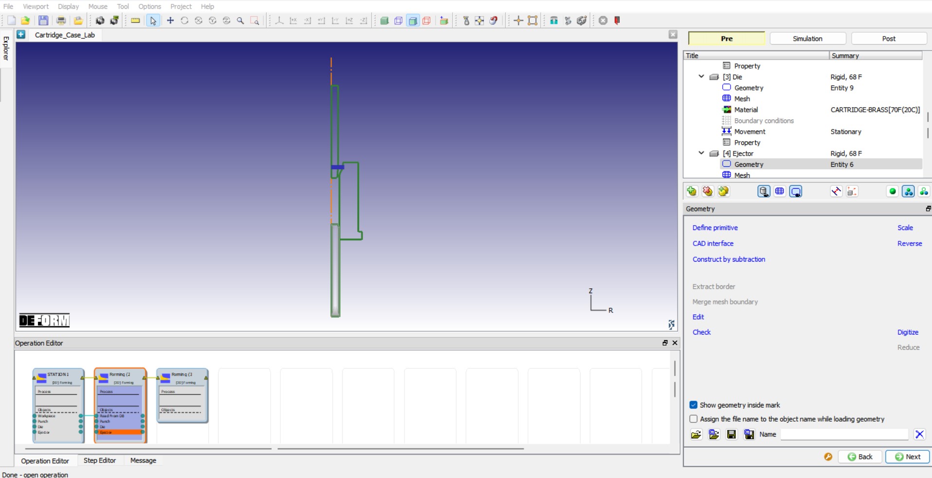
We will import the file “Ejector.geo ” for Ejector geometry by browsing the geometry file path located in DEFORM installation folder \2D\LABS\Cartridge_Lab directory using the ![]() (Load geometry from a file) button in Geometry page, see Fig. 2DCCDL1.19. Check the geometry using
(Load geometry from a file) button in Geometry page, see Fig. 2DCCDL1.19. Check the geometry using ![]() option to make sure the geometry is OK. We do not need to define mesh or movement controls for Ejector as the Ejector is a rigid object, stationary and we are not calculating temperature distribution over the Ejector, we will click
option to make sure the geometry is OK. We do not need to define mesh or movement controls for Ejector as the Ejector is a rigid object, stationary and we are not calculating temperature distribution over the Ejector, we will click ![]() button until we reach Scheduled positioning page.
button until we reach Scheduled positioning page.
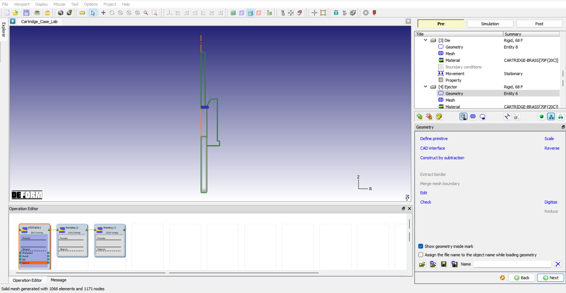
Loading Ejector geometry
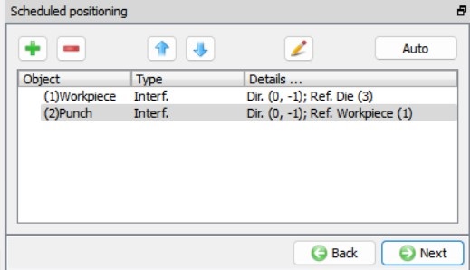
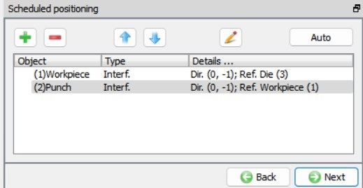
Defining Scheduled positioning
We will be using Scheduled positioning so that the objects are positioned automatically based on the sequence of positioning defined in the Scheduled positioning page before DB is generated in DB generation page. To schedule position for Station1 objects, click on ![]() button to add a positioning item and select
button to add a positioning item and select ![]() . Change the Positioning object to the Workpiece and the Reference object to the Die , select the Approach Direction to -Y. Click on
. Change the Positioning object to the Workpiece and the Reference object to the Die , select the Approach Direction to -Y. Click on ![]() and we can observe that a positioning step being added based on our definition in the Scheduled positioning page.
and we can observe that a positioning step being added based on our definition in the Scheduled positioning page.
Similarly, position Punch over Workpiece by clicking on ![]() button and select
button and select ![]() , change the Positioning Object to the Punch , the Reference object to the Workpiece and select the Approach Direction to -Y. We can observe the scheduled positioning sequence as shown in Fig. 2DCCDL1.20. Click on
, change the Positioning Object to the Punch , the Reference object to the Workpiece and select the Approach Direction to -Y. We can observe the scheduled positioning sequence as shown in Fig. 2DCCDL1.20. Click on ![]() to navigate to Contact page to define contact conditions.
to navigate to Contact page to define contact conditions.
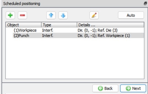
Scheduled positioning definition for Station1
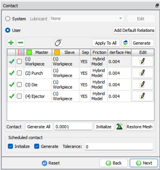
Defining contact conditions
As we are using schedule positioning to position the objects, we need to schedule the contact generation so that contacts between objects can be generated between the objects based on the positioning defined in the Schedule positioning. Turn on the checkboxes Initialize and Generate to initialize contacts and then generate new contacts based on the contact relations defined, see Fig. 2DCCDL1.21. Assign the default inter-object relationships using ![]() button. Click on the
button. Click on the ![]() button for one of the relationships. An Inter-object data window will open, select Hybrid type friction radio button in Deformation tab, define 0.1 value for both Coulomb and Shear. Click
button for one of the relationships. An Inter-object data window will open, select Hybrid type friction radio button in Deformation tab, define 0.1 value for both Coulomb and Shear. Click ![]() to exit the Inter-object data window. Click on
to exit the Inter-object data window. Click on ![]() to apply the same friction conditions defined for the selected relation to all other relations in the list, see Fig. 2DCCDL1.21. Since contacts will be generated during DB generation, we will click on
to apply the same friction conditions defined for the selected relation to all other relations in the list, see Fig. 2DCCDL1.21. Since contacts will be generated during DB generation, we will click on ![]() to navigate to Stopping controls page to define stopping controls.
to navigate to Stopping controls page to define stopping controls.

Defining contact conditions
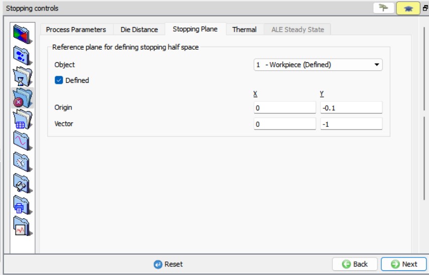
Stopping controls
We will be defining stopping controls so that simulation stops when the Workpiece crosses a plane. In Stopping controls page, click on Stoppingplane tab, turn on Defined checkbox and define Origin as (0,-0.1) and Vector as (0,-1), see Fig. 2DCCDL1.22. Click on ![]() to navigate to Step page to define simulation step controls.
to navigate to Step page to define simulation step controls.

Defining Stopping controls for Station1
Step Controls
We will be defining settings to control the simulation steps in Step page. Define Number of Steps for simulation as 10000 , Step increment to save steps into database as 10 and Die displacement per step as 0.001 , see Fig. 2DCCDL1.23. Click ![]() to Generate DB page.
to Generate DB page.
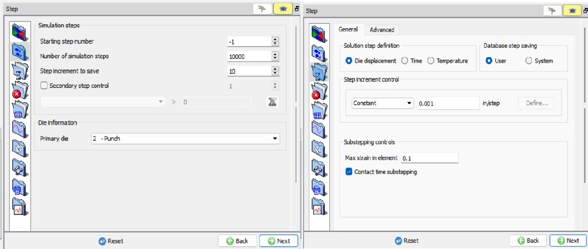
Simulation step controls for Station1
Generating Database
In Generate database page, click on the ![]() button, the data checking system will confirm that defined data is appropriate for running a simulation.Red marks indicate missing or incorrect data that will prevent a simulation from running. It is necessary to correct those errors before the database can be generated.
button, the data checking system will confirm that defined data is appropriate for running a simulation.Red marks indicate missing or incorrect data that will prevent a simulation from running. It is necessary to correct those errors before the database can be generated.
Yellow marks indicate data which may be suspect and should be reviewed. These should be investigated carefully, as they might result in system instability or erroneous (incorrect) results.
Review the data checking information. If there are no yellow or red marks, click the ![]() button.
button.
You should look for the words: Database has been generated in the Message tab. When you see this, it means that your inputs have been saved to the database.
Click on ![]() to proceed to set up ‘Station2’.
to proceed to set up ‘Station2’.
Setting up Station2:
Change the operation name to “Station2 “ for the 2nd Forming operation in Operation editor tab as done for first operation by double clicking on the operation name and press Enter in Keyboard after editing the operation name.
When we navigated to Station2, all objects from Station1 are moved to Station2 as Read from DB objects. In Station2, we will change the Die, Punch and Ejector geometries, and initialize the Strain, Damage and Velocity of the Workpiece to 0 as the Workpiece will undergo strain relaxation between the forming operations.
Select Geometry Type and Simulation modes
Keep the 2D Axisymmetric radio button selected as geometry type and click ![]() to continue to Simulation controls page. In Simulation controls page, uncheck the Heat transfer mode check box as shown in Fig. 2DCCDL1.3. of Station1 and click
to continue to Simulation controls page. In Simulation controls page, uncheck the Heat transfer mode check box as shown in Fig. 2DCCDL1.3. of Station1 and click ![]() until Workpiece page as we do not need any additional objects to be added to the Objects list for this operation.
until Workpiece page as we do not need any additional objects to be added to the Objects list for this operation.
Workpiece
Workpiece object type definition
We can notice that Object type of the Workpiece is Read from DB, the Workpiece object data will be read from the last step of the previous operation. We will keep the Workpiece as Read from DB, see Fig. 2DCCDL1.24. Click ![]() until Workpiece Properties page as we will not be redefining the mesh or bcc for the Workpiece.
until Workpiece Properties page as we will not be redefining the mesh or bcc for the Workpiece.
Workpiece object page
Setting Limiting strain rate value for Workpiece
We will change the Limiting Strain rate value to capture the lower strain rates in the Workpiece. We will turnonRedefine Strain rate checkbox and Limiting as ‘0.001 ’, see Fig. 2DCCDL1.25. Click ![]() to Initialize page to initialize Workpiece conditions.
to Initialize page to initialize Workpiece conditions.
Redefining Limiting Strain rate for Workpiece
Initializing Workpiece conditions
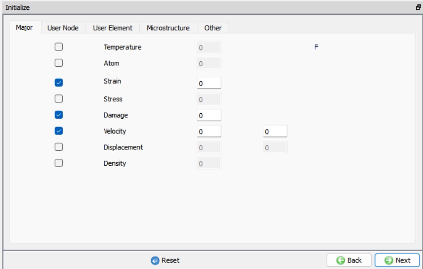
In Initialize page, turn on Strain , Damage and Velocity check boxes and define value as ‘0 ’ so that we can take into account the strain relaxation of the Workpiece, see Fig. 2DCCDL1.26. Click ![]() until Punch object page.
until Punch object page.
Initializing Workpiece conditions in Station2
Punch
Punch object type definition
We need to change the Punch geometry for the Station2, hence change the Object type from Read from DB to Rigid , see Fig. 2DCCDL1.27. Click ![]() to Punch Geometry page.
to Punch Geometry page.
Punch object page
Changing Punch Geometry
In Punch Geometry page, import the file “Punch2.geo ” by browsing the geometry file path located in DEFORM installation folder \2D\LABS\Cartridge_Lab directory, see Fig. 2DCCDL1.28. Check the geometry using ![]() option to make sure the geometry is OK. Click
option to make sure the geometry is OK. Click ![]() until we reach Punch movement page.
until we reach Punch movement page.
Punch geometry in Station2
Assign Movement to Punch in Station2
The default mode is constant speed. Input a value of 10 in/sec for the Constant value and confirm that the Direction is -Y. Click ![]() until Die object page.
until Die object page.
Die
Die object type definition
We need to change the Die geometry for the Station2, hence change the Object type from Read from DB to Rigid. Click ![]() to Die Geometry page.
to Die Geometry page.
Changing Die Geometry
Click the ![]() (Load geometry from a file) button and import the file “Die2.geo ” by browsing the geometry file path located in DEFORM installation folder \2D\LABS\Cartridge_Lab directory, see Fig. 2DCCDL1.29. Check the geometry using
(Load geometry from a file) button and import the file “Die2.geo ” by browsing the geometry file path located in DEFORM installation folder \2D\LABS\Cartridge_Lab directory, see Fig. 2DCCDL1.29. Check the geometry using ![]() option to make sure the geometry is OK. Click
option to make sure the geometry is OK. Click ![]() until Ejector object page.
until Ejector object page.
Die geometry for Station2
Ejector
Ejector object type definition
We need to change the Ejector geometry for the Station2, hence change the Object type from Read from DB to Rigid. Click ![]() to Ejector Geometry page.
to Ejector Geometry page.
Changing Ejector Geometry
Click the ![]() (Load geometry from a file) button and import the file “Ejector2.geo ” by browsing the geometry file path located in DEFORM installation folder \2D\LABS\Cartridge_Lab directory, see Fig. 2DCCDL1.30. Check the geometry using
(Load geometry from a file) button and import the file “Ejector2.geo ” by browsing the geometry file path located in DEFORM installation folder \2D\LABS\Cartridge_Lab directory, see Fig. 2DCCDL1.30. Check the geometry using ![]() option to make sure the geometry is OK. Click
option to make sure the geometry is OK. Click ![]() until Scheduled positioning page.
until Scheduled positioning page.
Ejector geometry for Station2
Scheduled Positioning
Currently, we do not have the Workpiece geometry output from Station1 simulation to position the dies as the Station1 is not yet simulated. Hence, we will use schedule positioning method which will position dies during DB generation for Station2 with respect to the Workpiece geometry output from Station1, Workpiece object type is Read from DB.
To schedule position for Station2 objects, click on ![]() button to add a positioning item and select
button to add a positioning item and select ![]() . Change the Positioning object to the Workpiece and the Reference object to the Die , select the Approach Direction to -Y. Click on
. Change the Positioning object to the Workpiece and the Reference object to the Die , select the Approach Direction to -Y. Click on ![]() and we can observe that a positioning step being added based on our definition in the Scheduled positioning page. Similarly, position Punch over Workpiece by clicking on
and we can observe that a positioning step being added based on our definition in the Scheduled positioning page. Similarly, position Punch over Workpiece by clicking on ![]() button and select
button and select ![]() , change the Positioning Object to the Punch , the Reference object to the Workpiece and select the Approach Direction to -Y. We can observe the scheduled positioning sequence as shown in Fig. 2DCCDL1.31. Click on
, change the Positioning Object to the Punch , the Reference object to the Workpiece and select the Approach Direction to -Y. We can observe the scheduled positioning sequence as shown in Fig. 2DCCDL1.31. Click on ![]() to navigate to Contact page to define contact conditions.
to navigate to Contact page to define contact conditions.
Scheduled positioning definition for Station2
Defining Contact conditions and scheduling contact generation for Station2
We need to schedule the contact generation so that contacts between objects can be generated with between the objects based on the positioning defined in the Schedule positioning. Turn on the check boxes Initialize and Generate to initialize contacts and then generate new contacts based on the contact relations defined, see Fig. 2DCCDL1.32. Assign the default inter-object relationships using ![]() button. Click on the
button. Click on the ![]() button for one of the relationships. Select Hybrid type friction radio button in Deformation tab, define 0.1 value for both Coulomb and Shear in Inter-object data window. Click
button for one of the relationships. Select Hybrid type friction radio button in Deformation tab, define 0.1 value for both Coulomb and Shear in Inter-object data window. Click ![]() to exit the Inter-object data window. Click on
to exit the Inter-object data window. Click on ![]() to apply the same friction conditions defined for the selected relation to all other relations in the list, see Fig. 2DCCDL1.32. Click on
to apply the same friction conditions defined for the selected relation to all other relations in the list, see Fig. 2DCCDL1.32. Click on ![]() to navigate to Stopping controls page to define stopping controls.
to navigate to Stopping controls page to define stopping controls.
Defining contact conditions for Stage 2
Stopping controls for Station2
In Stopping controls page, we will define stopping plane as stopping criteria. Click on Stoppingplane tab, turn on Defined checkbox and define origin as (0 ,-0.1) and vector as (0 ,-1) see Fig. 2DCCDL1.33. Click on ![]() to navigate to Step page to define simulation step controls.
to navigate to Step page to define simulation step controls.
Stopping plane stopping criteria for Station2
Step Controls for Station2
In Steps page, define Number of Steps as 10000 , Step increment to save steps into database as 10 and Die displacement per step as 0.001. Click ![]() to Generate DB page, since database will be generated during runtime after completion of the Station1 simulation for a batch mode operation setup, we will click on
to Generate DB page, since database will be generated during runtime after completion of the Station1 simulation for a batch mode operation setup, we will click on ![]() to setup Station3.
to setup Station3.
Station3
Change the operation name to “Station3 “ for the 3rd Forming operation in Operation editor tab as done in previous operations setup by double clicking on the operation name and press Enter in Keyboard after editing the operation name.
Similar to Station2 for Station3, we will change the Die, Punch and Ejector geometries, and initialize the Strain, Damage and Velocity of the Workpiece to 0 as the Workpiece will undergo strain relaxation between the forming operations.
Select Geometry Type and Simulation modes
Keep the 2D Axisymmetric radio button selected as geometry type and click ![]() to continue to Simulation controls page. In Simulation controls page, uncheck the Heat transfer mode check box as shown in Fig. 2DCCDL1.4. of Station1 and click
to continue to Simulation controls page. In Simulation controls page, uncheck the Heat transfer mode check box as shown in Fig. 2DCCDL1.4. of Station1 and click ![]() until Workpiece page as we do not need any additional objects to be added to the Objects list for this operation.
until Workpiece page as we do not need any additional objects to be added to the Objects list for this operation.
Workpiece
Workpiece object type definition
We can notice that Object type of the Workpiece is Read from DB, the Workpiece object data will be read from the last step of the previous operation. We will keep the Workpiece as Read from DB. Click ![]() until Workpiece Properties page.
until Workpiece Properties page.
Setting Limiting strain rate value for Workpiece
We will turn on Redefine Strainrate checkbox and Limiting as ‘0.001 ’, see Fig. 2DCCDL1.34. Click ![]() to Initialize page to initialize Workpiece conditions.
to Initialize page to initialize Workpiece conditions.

Redefining Limiting Strain rate for Workpiece
Initializing Workpiece conditions
In Initialize page, turn on Strain, Damage, Velocity checkboxes and define value as ‘0 ’ so that we can take into account the strain relaxation of the Workpiece, see Fig. 2DCCDL1.35. Click ![]() until Punch object page.
until Punch object page.

Initializing Workpiece conditions in Station3
Punch
Punch object type definition
We need to change the Punch geometry for the Station3, hence change the Object type from Read from DB to Rigid , see Fig. 2DCCDL1.36. Click ![]() to Punch Geometry page.
to Punch Geometry page.
Punch object page Station3
Changing Punch Geometry
In Punch Geometry page, import the file “Punch3.geo ” by browsing the geometry file path located in DEFORM installation folder \2D\LABS\Cartridge_Lab directory, see Fig. 2DCCDL1.37. Check the geometry using ![]() option to make sure the geometry is OK. Click
option to make sure the geometry is OK. Click ![]() until we reach Punch movement page.
until we reach Punch movement page.
Punch geometry for Station3
Assign Movement to Punch in Station2
The default mode is constant speed. Input a value of 10 in/sec for the Constant value and confirm that the Direction is -Y. Click ![]() until Die object page.
until Die object page.
Die
Die object type definition
We need to change the Die geometry for the Station3 , hence change the Object type from Read from DB to Rigid. Click ![]() to Die Geometry page.
to Die Geometry page.
Changing Die Geometry
Click the ![]() (Load geometry from a file) button and import the file “Die3.geo ” by browsing the geometry file path located in DEFORM installation folder \2D\LABS\Cartridge_Lab directory, see Fig. 2DCCDL1.38. Check the geometry using
(Load geometry from a file) button and import the file “Die3.geo ” by browsing the geometry file path located in DEFORM installation folder \2D\LABS\Cartridge_Lab directory, see Fig. 2DCCDL1.38. Check the geometry using ![]() option to make sure the geometry is OK. Click
option to make sure the geometry is OK. Click ![]() until Ejector object page.
until Ejector object page.
Die geometry for Station3
Ejector
Ejector object type definition
We need to change the Ejector geometry for the Station3, hence change the Object type from Read from DB to Rigid. Click ![]() to Ejector Geometry page.
to Ejector Geometry page.
Changing Ejector Geometry
Click the ![]() (Load geometry from a file) button and import the file “Ejector3.geo ” by browsing the geometry file path located in DEFORM installation folder \2D\LABS\Cartridge_Lab directory, see Fig. 2DCCDL1.39. Check the geometry using
(Load geometry from a file) button and import the file “Ejector3.geo ” by browsing the geometry file path located in DEFORM installation folder \2D\LABS\Cartridge_Lab directory, see Fig. 2DCCDL1.39. Check the geometry using ![]() option to make sure the geometry is OK. Click
option to make sure the geometry is OK. Click ![]() until Scheduled positioning page.
until Scheduled positioning page.
Ejector geometry for Station3
Scheduled Positioning
Similar to Station2, we will use Schedule positioning for Station3. Add schedule positioning of interference for Workpiece with Die as Reference object in-Y direction. Add item of interference positioning Punch with Workpiece as Reference object in -Y direction. We can observe the scheduled positioning sequence as shown in Fig. 2DCCDL1.40. Click on ![]() to navigate to Contact page to define contact conditions.
to navigate to Contact page to define contact conditions.
Scheduled positioning definition for Station3
Defining Contact conditions and scheduling contact generation for Station3
Similar to Station 2, we will schedule the contact generation for Station3, turn on the checkboxes Initialize and Generate to initialize contacts and then generate new contacts, see Fig. 2DCCDL1.41. ssign the default inter-object relationships using ![]() button. Click on the
button. Click on the ![]() button for one of the relationships. Select Hybrid type friction radio button in Deformation tab, define 0.1 value for both Coulomb and Shear in Inter-object data window. Click
button for one of the relationships. Select Hybrid type friction radio button in Deformation tab, define 0.1 value for both Coulomb and Shear in Inter-object data window. Click ![]() to exit the Inter-object data window. Click on
to exit the Inter-object data window. Click on ![]() to apply the same friction conditions defined for the selected relation to all other relations in the list, see Fig. 2DCCDL1.41. Click on
to apply the same friction conditions defined for the selected relation to all other relations in the list, see Fig. 2DCCDL1.41. Click on ![]() to navigate to Stopping controls page to define stopping controls.
to navigate to Stopping controls page to define stopping controls.
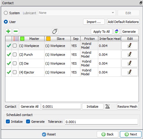
Defining contact conditions for Stage 3
Stopping controls for Station3
In Stopping controls page, click on Stoppingplane tab, turn on Definedcheckbox and define origin as (0,-0.25) and vector as (0 ,-1) see Fig. 2DCCDL1.42. Click on ![]() to navigate to Step page to define simulation step controls.
to navigate to Step page to define simulation step controls.
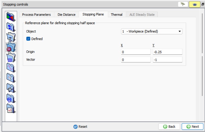
Stopping plane stopping criteria in 3rd operation
Step Controls for Station3
In Steps page, define Number of Steps as 10000 , Step increment to save steps into database as 10 and Die displacement per step as 0.001. Click ![]() to Generate DB page, since database will be generated during runtime after completion of the Station2 simulation for a batch mode operation setup, we will now run the simulation.
to Generate DB page, since database will be generated during runtime after completion of the Station2 simulation for a batch mode operation setup, we will now run the simulation.
Running Simulation
Switch to the Simulation mode by clicking on ![]() button above the operation tree. Click on the
button above the operation tree. Click on the ![]() action label to open the Run Options dialog as shown in Fig. 2DCCDL1.43. Use the default Continue Run option to select “Continue from the last step ” option and then select the Simulation mode as Interactive and click on
action label to open the Run Options dialog as shown in Fig. 2DCCDL1.43. Use the default Continue Run option to select “Continue from the last step ” option and then select the Simulation mode as Interactive and click on ![]() button to run the simulation.
button to run the simulation.
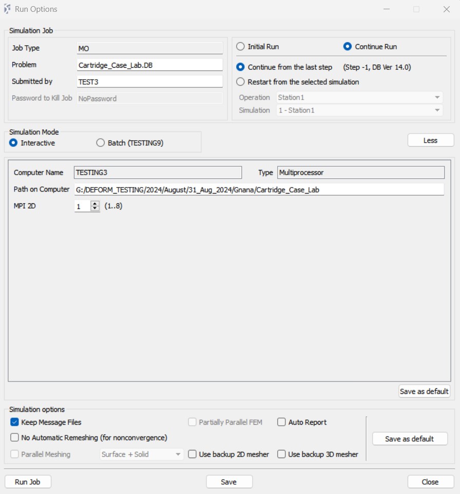
Run Simulation popup window
Post Processing
Once the simulation is completed, the DB will be moved to Finished in Simulation tab and in Log file we can observe the message as “Multiple operations completed.”. We can now switch to the Post mode by clicking on the ![]() button to view the simulation results. In Post, Step browser below the graphic area indicates step numbers available from the different operations simulated see Fig. 2DCCDL1.44. A set of state variables available from the ‘Post ’ menu can be used review the model response, see Fig. 2DCCDL1.45. shows Damage state variable distribution at the last step of Station 1, Station 2 and Station 3. Fig. 2DCCDL1.46. shows Effective strain state variable distribution at the last step of Station 1, Station 2 and Station 3. Fig. 2DCCDL1.47. shows Effective stress state variable distribution at the last step of Station 1, Station 2 and Station 3.
button to view the simulation results. In Post, Step browser below the graphic area indicates step numbers available from the different operations simulated see Fig. 2DCCDL1.44. A set of state variables available from the ‘Post ’ menu can be used review the model response, see Fig. 2DCCDL1.45. shows Damage state variable distribution at the last step of Station 1, Station 2 and Station 3. Fig. 2DCCDL1.46. shows Effective strain state variable distribution at the last step of Station 1, Station 2 and Station 3. Fig. 2DCCDL1.47. shows Effective stress state variable distribution at the last step of Station 1, Station 2 and Station 3.
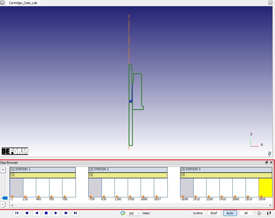
Step list in Post processor
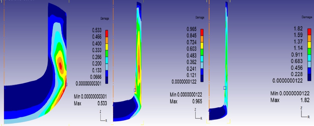
Damage results at last step of last operation
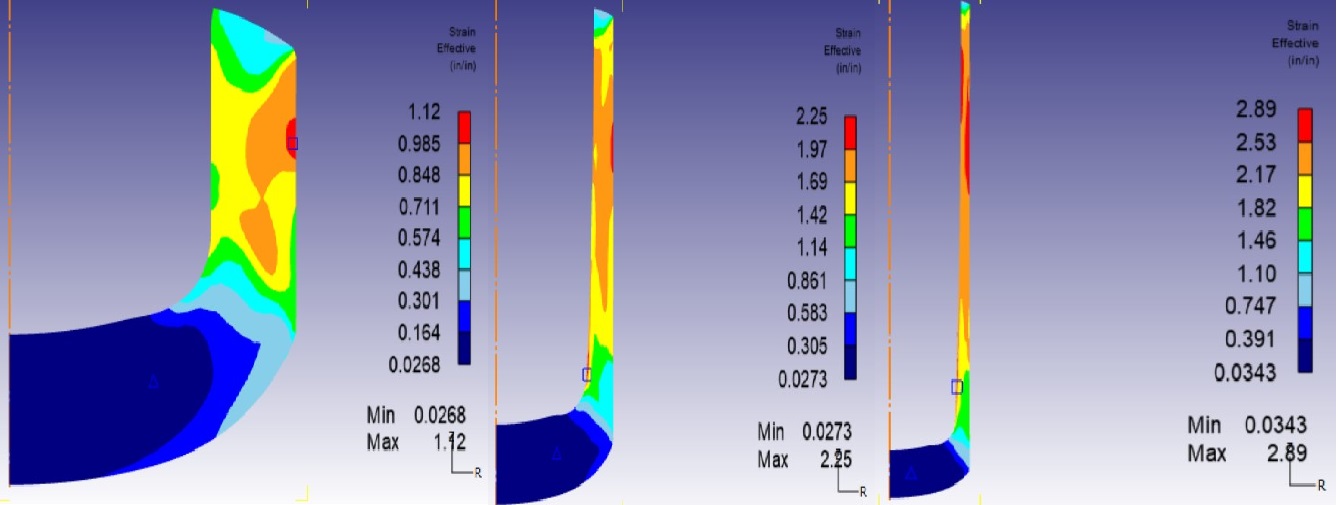
Strain effective results at last step of last operation
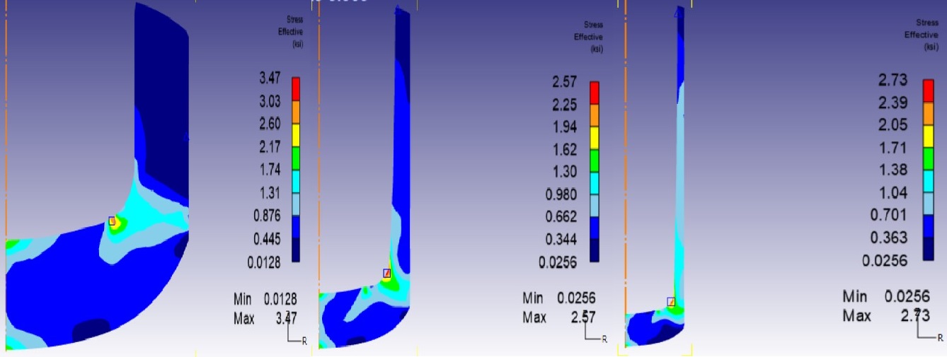
Stress effective results at last step of last operation