Stress Relaxation Lab
Problem Summary:
In this lab, we will be demonstrating about how to set up a simulation to predict the residual stresses during Stress Relaxation process after Quenching and after Machining using machining distortion. The sequence of operations involved in this set up are,
Furnace Heating -> Quenching -> Stress relaxation (Creep)-> Cooling -> Boolean -> Machining Distortion
The part is of a cylindrical shape, initially the part is heated up to 1200°C for about 1000 Sec in a furnace using heating operation. It is followed by a quenching operation where the part is cooled rapidly for about 600 seconds using different Convection coefficients over the parts surface. To analyze distortion during Quenching deformation mode is turned on. Quenching is followed by a stress relaxation operation where the part is heated to temperature of 700°C and soaked for three hours at 700°C. During stress relaxation, creep is turned on to study the deformation due to creep. After stress relaxation operation, the part is cooled to room temperature in air for about half an hour. After air cooling, using Boolean operation a through hole is created at the centre of the part. It is followed by a machining distortion operation to capture residual stresses after machining. The entire sequence can be setup using MO and all the operations can be simulated without user intervention in batch mode.
1.1. Creating New Problem and Adding Operations
1.1.1. Creating New Problem
1.1.2. Adding other operations to Operation Editor
1.2. Operation1: Furnace Heating Setup
1.2.1. Select Geometry Type
1.2.2. Select Heat Transfer Type for Furnace Heating
1.2.3. Set Process Conditions for Furnace Heating
1.2.4. Select Simulation Controls for Furnace Heating
1.2.5. Import and edit Workpiece Material
1.2.6. Adding objects for Furnace Heating Operation
1.2.7. Define Workpiece
1.2.8. Create Workpiece Geometry
1.2.9. Mesh generation
1.2.10. Assign Workpiece Material
1.2.11. Define Workpiece Boundary Conditions
1.2.12. Define Step Controls for Furnace Heating
1.2.13. Generate Database
1.3. Operation2: Quenching
1.3.1. Select Simulation modes for Quenching
1.3.2. Redefine Workpiece Boundary Conditions
1.3.3. Set Deformation property settings for Quenching
1.3.4. Set Step, stopping and function time controls for Quenching
1.4. Operation3: Stress Relaxation (Creep)
1.4.1. Select Heat Transfer Type for Stress Relaxation
1.4.2. Set Process Condition for Stress Relaxation
1.4.3. Set Simulation modes for Stress Relaxation
1.4.4. Remove the additional objects for Stress Relaxation
1.4.5. Redefine Workpiece Boundary Conditions
1.4.6. Activating Creep calculation for Stress Relaxation
1.4.7. Set Step function time and out put controls for Stress Relaxation
1.5. Operation4: Cooling
1.5.1. Select Heat Transfer Type for Cooling
1.5.2. Set Process Condition for Cooling
1.5.3. Set Simulation modes for Cooling
1.5.4. Remove the additional objects for Cooling
1.5.5. Set Step controls and function time for Cooling
1.6. Operation5: Boolean
1.6.1. Select Objects for Boolean
1.6.2. Creating Cutter geometry for Boolean
1.7. Operation6: Machining Distortion
1.7.1. Select Objects for Machining Distortion
1.7.2. Workpiece Selection page for Machining Distortion
1.7.3. Defining Fixture 1 for Machining Distortion
1.7.4. Defining Fixture 2 for Machining Distortion
1.7.5. Defining Pass for Machining Distortion
1.7.6. Scheduled positioning for Machining Distortion
1.7.7. Schedule Inter-Object Contact Relationships for Machining Distortion
1.7.8. Pass Boolean Preview for Machining Distortion
1.7.9. Set Step controls for Machining Distortion
1.8. Running Simulation
1.9. Post Processing
Creating New problem and Adding Operations
Creating New Problem
On a Windows machine, go to the ![]() button select DEFORM-v1x.xxx (.xxx indicates version number E.g. v14.0.2) and select DEFORM GUI Main v1x.x from the menu. The DEFORM GUI Main window will appear.
button select DEFORM-v1x.xxx (.xxx indicates version number E.g. v14.0.2) and select DEFORM GUI Main v1x.x from the menu. The DEFORM GUI Main window will appear.
Create a new problem either by selecting File![]() New Problem or by clicking the New Problem
New Problem or by clicking the New Problem ![]() icon. The Problem Setup window will appear. Select “ Integrated Manufacturing Process “ radio button and unit system as “SI “ radio button in unit field. Define Problem Name as “ Stress_Relaxation_Lab1 “ and make sure the “Show option dialog ” check box is turned on (if we do not turn on the “Show option dialog” check box, then we will not get the New Project dialog). Then click on
icon. The Problem Setup window will appear. Select “ Integrated Manufacturing Process “ radio button and unit system as “SI “ radio button in unit field. Define Problem Name as “ Stress_Relaxation_Lab1 “ and make sure the “Show option dialog ” check box is turned on (if we do not turn on the “Show option dialog” check box, then we will not get the New Project dialog). Then click on ![]() button to open a new problem using the Deform Integrated Manufacturing Process.
button to open a new problem using the Deform Integrated Manufacturing Process.
Multiple operation wizard will open with the New Project dialog, at this point user will be prompted to specify a project name (system will create a separate folder with this project name) and title for this session. In this session, we will use ‘Stress_Relaxation_Lab1 ’ as the project name. Add 2d Heat Transfer operation by turning on First operation checkbox and selecting it from pull down list. Click on ![]() to continue to open the operation. (See Fig. SRL1.1.)
to continue to open the operation. (See Fig. SRL1.1.)
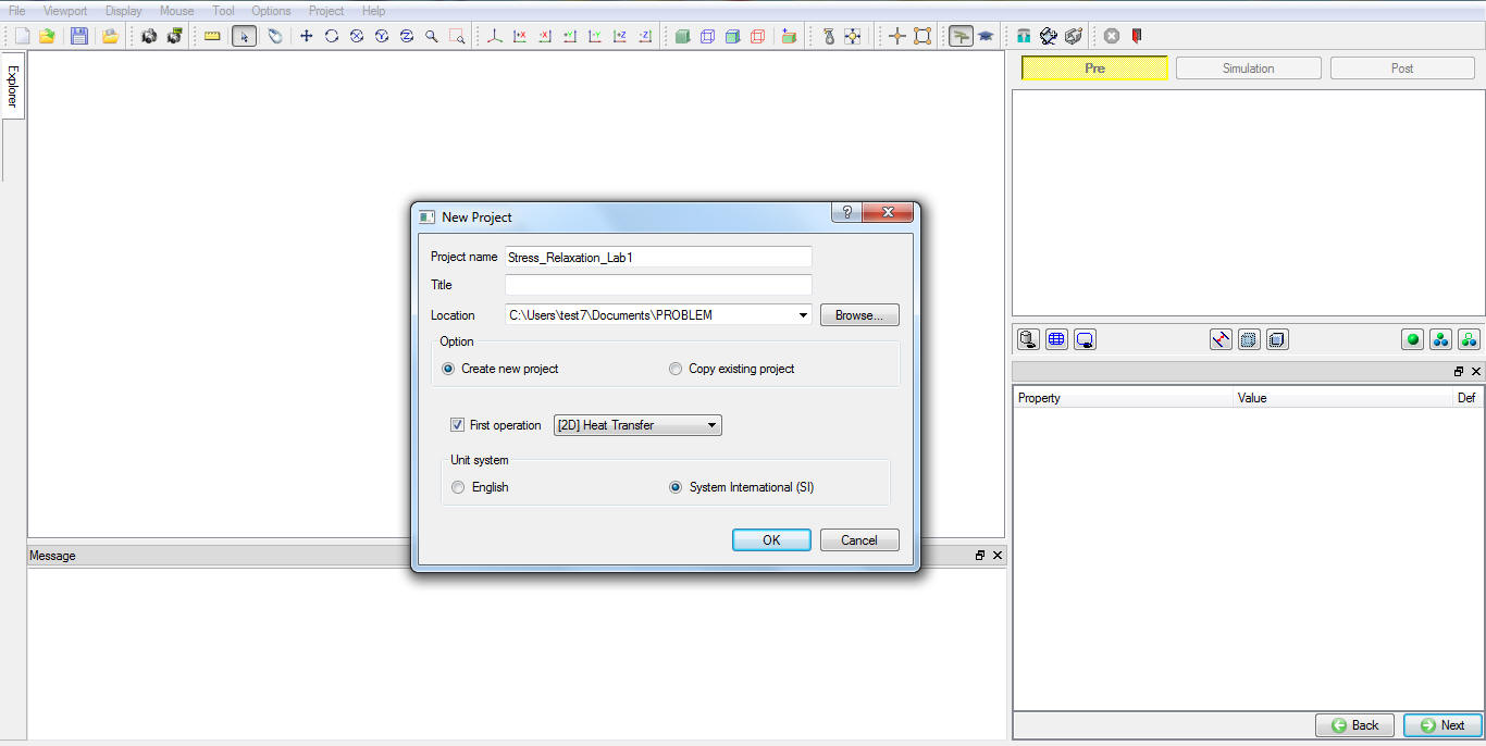
MO wizard New Project
Adding other operations to Operation Editor
Multiple Operation wizard will opens new project with one 2d Heat transfer operation. Add one 2d forming operation for Quenching followed by 2d Heat transfer operations for stress relaxation and cooling operations, one Boolean operation and one Machining Distortion operation from Operations Explorer list clicking ![]() button as shown in Fig. SRL1.2.
button as shown in Fig. SRL1.2.
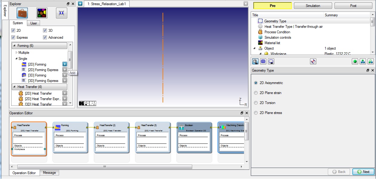
Adding all six operations to Operation editor from Explorer
Operation1: Furnace Heating Setup
Select first heat transfer operation and change the operation name to “Heating “ by double clicking on Operation name in Operation Editor window as shown in Fig. SRL1.3. and press Enter in Keyboard.
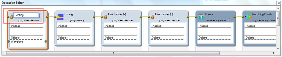
Name the first operation as Heating
Select Geometry Type
In this lab, we will be using Axisymmetric geometries, so activate 2D Axisymmetric radio button in geometry type window as shown in Fig. SRL1.2., then click ![]() to continue.
to continue.
Select Heat Transfer Type for Furnace Heating
Select Heat in Furnace heat transfer type for Furnace heating operation as shown in Fig. SRL1.4. This will set the default heat transfer settings for heating operation. Click ![]() to continue.
to continue.
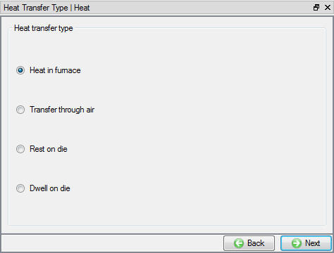
Heat transfer type selection for Furnace Heating
Set Process Conditions for Furnace Heating
Define Heatingtime as 1000 sec at furnace temperature or environmenttemperature as 1200 °C as shown in Fig. SRL1.5. and click ![]() to continue.
to continue.
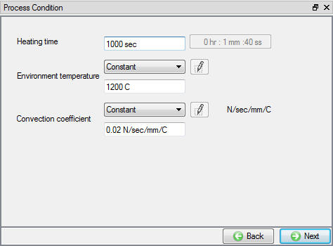
Process Condition settings for Furnace Heating
Select Simulation Controls for Furnace Heating
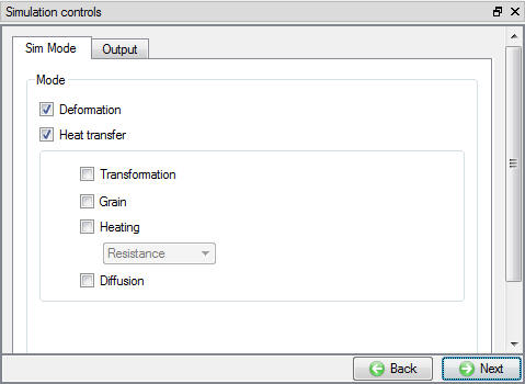
Keep only Heat Transfer mode checked, as we require only temperature distribution in the part as shown in Fig. SRL1.6. and click ![]() to continue.
to continue.
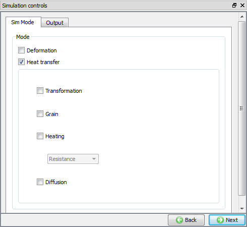
Simulation Controls settings for Furnace Heating
Import and edit Workpiece Material
In Material window, load the material IN718_machining-AMTC from DEFORM Material library, available under Superalloy category, using ![]() (Load material data from library) option. This can be done as shown in Fig. SRL1.7. by clicking
(Load material data from library) option. This can be done as shown in Fig. SRL1.7. by clicking ![]() button. Material can also be loaded from Materials list in Explorer.
button. Material can also be loaded from Materials list in Explorer.
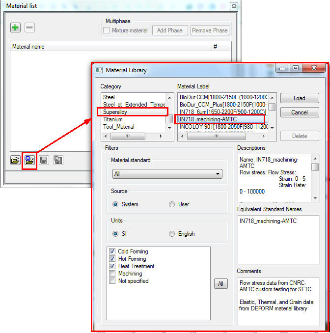
Importing Workpiece material from DEFORM library
Then click ![]() for IN718_machining-AMTC material properties page. IN718_machining-AMTC material does not have creep properties defined. Hence, select Power law model for creep in Plastic properties tab (See Fig. SRL1.8.) and click on
for IN718_machining-AMTC material properties page. IN718_machining-AMTC material does not have creep properties defined. Hence, select Power law model for creep in Plastic properties tab (See Fig. SRL1.8.) and click on ![]() (Define) button next to Creep. Define the gamma value as6e-06 and m value as 1 in first row (See Fig. SRL1.9.). Then click
(Define) button next to Creep. Define the gamma value as6e-06 and m value as 1 in first row (See Fig. SRL1.9.). Then click ![]() to define objects required for furnace heating operation.
to define objects required for furnace heating operation.
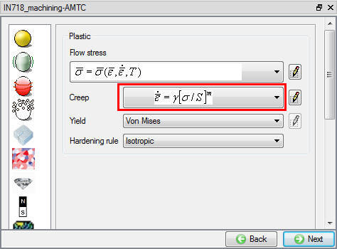
Selecting Creep power law model
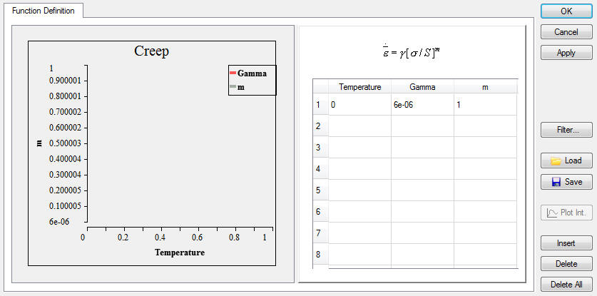
Creep power law definition
Adding objects for Furnace Heating Operation
Furnace heating requires only one object, hence add one object if already not available using add button. Click ![]() .
.
Define Workpiece
In Workpiece object window select the object type as ‘Elasto-Plastic ’ and define object temperature as 20 °C (See Fig. SRL1.10.). Keep the object name as workpiece. Click on ![]() to Workpiece geometry page.
to Workpiece geometry page.
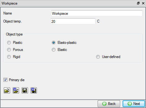
Workpiece Object definition
Create Workpiece Geometry
In the Geometry page, select ![]() and define cylinder geometry parameters as, Radius10 mm, Height8 mm and cornerradius0.5 mm (See Fig. SRL1.11.). Click on
and define cylinder geometry parameters as, Radius10 mm, Height8 mm and cornerradius0.5 mm (See Fig. SRL1.11.). Click on ![]() button to generate geometry and close Geometry Primitive window. Check geometry and click
button to generate geometry and close Geometry Primitive window. Check geometry and click ![]() to Workpiece material definition page.
to Workpiece material definition page.
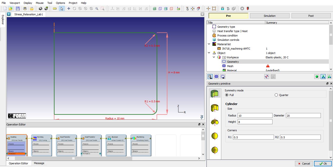
Defining workpiece geometry
Mesh generation
The default number of elements** are adequate for this lab, so keep the target number of elements as **1000 and click on ![]() to generate the Mesh (See Fig. SRL1.12.). Click on
to generate the Mesh (See Fig. SRL1.12.). Click on ![]() to define Workpiece BCC.
to define Workpiece BCC.
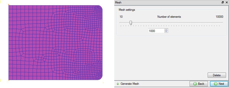
Workpiece mesh page
Assign Workpiece Material
To assign material for workpiece select the materialIN718_machining-AMTC from material window. This can be done as shown in Fig. SRL1.13. Click on ![]() to mesh page.
to mesh page.
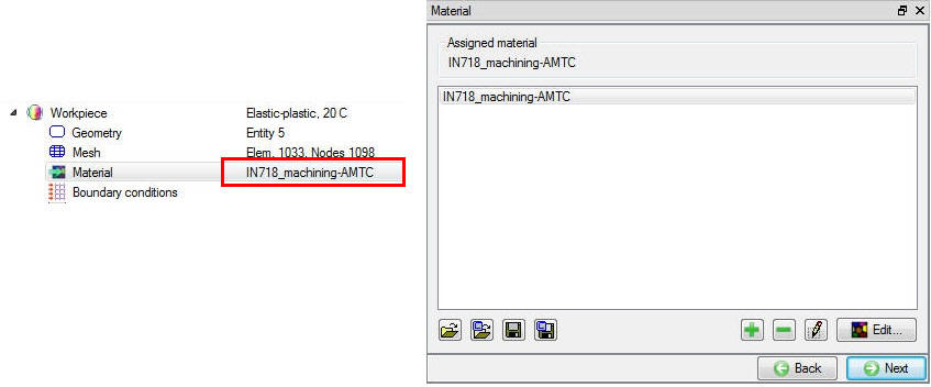
Workpiece material page
Define Workpiece Boundary Conditions
In BCC page, expand the Deformation BCC branch and check whether X Velocity fixed along the symmetric axis of the object. As Workpiece shrinks and expands in subsequent operations, to avoid Workpiece displacement in Y-direction fix the bottom left corner node velocity in Y direction as shown in Fig. SRL1.14.
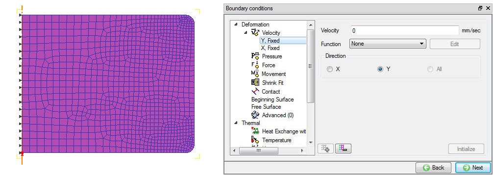
Velocity BCC to avoid distortion
Check the default assigned Heat exchange with Environment BCC to the entire outer surface of the Billet. In this lab,we will be defining location dependant HTC and Emissivity hence we need to delete default Heat exchange with Environment BCC by selecting it and clicking on ![]() button. We will be defining three different location dependant HTC and Emissivity BCC’s by dividing the entire outer surface of the workpiece as three different zones. To define location dependant HTC and Emissivity for the first zone, select the Advanced branch under Thermal BCC, select the outer surface of the Workpiece from lower left corner to mid-point of lower right corner curve using Start and End point selection method. Select Env. Temp. as function of time and import the function data file Stress_Relaxation_Oprns_EnvTemp_fun_data.dat from DEFORM installation folder \2D\Labs directory. Click on
button. We will be defining three different location dependant HTC and Emissivity BCC’s by dividing the entire outer surface of the workpiece as three different zones. To define location dependant HTC and Emissivity for the first zone, select the Advanced branch under Thermal BCC, select the outer surface of the Workpiece from lower left corner to mid-point of lower right corner curve using Start and End point selection method. Select Env. Temp. as function of time and import the function data file Stress_Relaxation_Oprns_EnvTemp_fun_data.dat from DEFORM installation folder \2D\Labs directory. Click on ![]() (Define) button to view the function data, data is defined for the entire time zone from Furnace Heating till Cooling operation and is as shown in Fig. SRL1.15.
(Define) button to view the function data, data is defined for the entire time zone from Furnace Heating till Cooling operation and is as shown in Fig. SRL1.15.
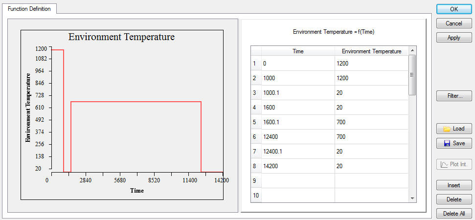
Environment temperature function of time
Click ![]() to close the function definition window. Define Conv. Coef. as 0.01 and Emissivity as 0.1 , click on
to close the function definition window. Define Conv. Coef. as 0.01 and Emissivity as 0.1 , click on ![]() button to define the advanced BCC. (See Fig. SRL1.16.)
button to define the advanced BCC. (See Fig. SRL1.16.)
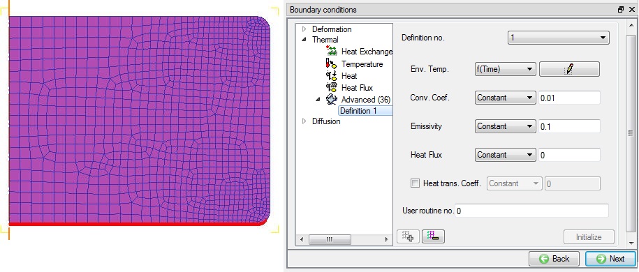
First Zone advanced thermal BCC definition
To define second zone, select from bottom right curve mid-point to top right curve mid-point using Start and End point selection method. Define the Env. Temp. as function of time importing the same .dat file as used in first zone. Define Conv. Coef. as 0.024 and Emissivity as 0.2, click on ![]() button to define the advanced BCC. (See Fig. SRL1.17.)
button to define the advanced BCC. (See Fig. SRL1.17.)
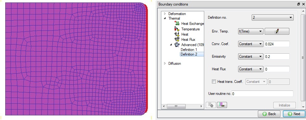
Second Zone advanced thermal BCC definition
Select remaining surface except symmetric axis as third zone and define Env. Temp. as function of time importing the same .dat file as used in first zone. Define Conv. Coef. as 0.048 and Emissivity as 0.3, click on ![]() button to define the advanced BCC. (See Fig. SRL1.18.)
button to define the advanced BCC. (See Fig. SRL1.18.)
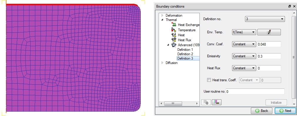
Third Zone advanced thermal BCC definition
Click ![]() until Step controls page as there is no object positioning and Thermal stopping controls definition is required.
until Step controls page as there is no object positioning and Thermal stopping controls definition is required.
Define Step Controls for Furnace Heating
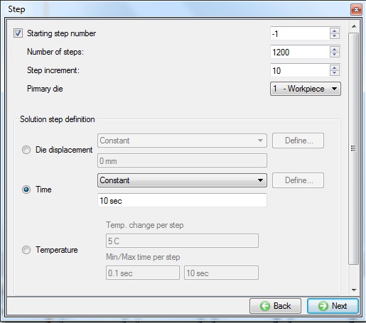
Set the number of simulation steps as 1200 at 1 sec/step and step increment to save as 10 steps (See Fig. SRL1.19.). Click ![]() to proceed to the database generation stage.
to proceed to the database generation stage.
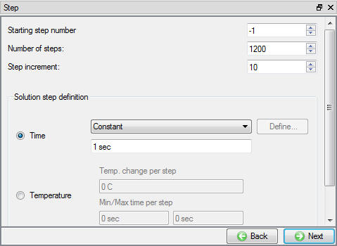
Simulation controls settings for Furnace Heating
Generate Database
In the database generation page, user can check the data required for the analysis and proceed to generate the database (See Fig. SRL1.20.). User is required to generate the database for the first operation in any multiple operations we only need to setup the process data and simulation controls. Click on ![]() to proceed to the next operation ‘Quenching ’.
to proceed to the next operation ‘Quenching ’.
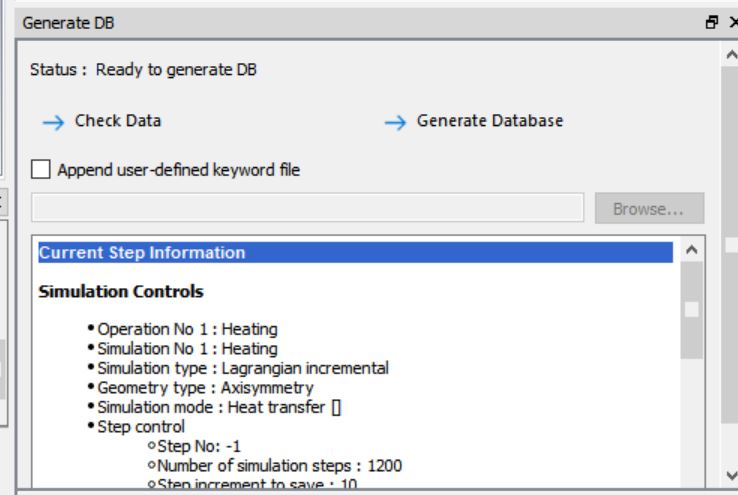
Database Generation window for first operation
Operation 2: Quenching
In this operation, we will be cooling workpiece rapidly for about 600 secs using different convection coefficients on three different zones defined in previous Furnace heating operation setup.
Select Simulation modes for Quenching
For second operation change the operation name to “Quenching “ in Operation editor tab as done for first operation. Click ![]() in geometry type page as default selection of Axisymmetric is right. In simulation control page make sure both Heat transfer and Deformation modes are checked as shown in Fig. SRL1.21.
in geometry type page as default selection of Axisymmetric is right. In simulation control page make sure both Heat transfer and Deformation modes are checked as shown in Fig. SRL1.21.
Simulation controls for quenching operation
Click ![]() until Workpiece object window and accept object type as ‘Read from DB’ (See Fig. SRL1.22.). This indicates that workpiece thermal history from the furnace heating operation will be available as a starting data for this operation. Click on
until Workpiece object window and accept object type as ‘Read from DB’ (See Fig. SRL1.22.). This indicates that workpiece thermal history from the furnace heating operation will be available as a starting data for this operation. Click on ![]() until Workpiece BCC page.
until Workpiece BCC page.
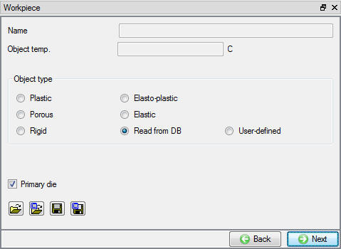
Read from DB object selection for workpiece
Redefine Workpiece Boundary Conditions
As we need to change the convection coefficients and emissivity of the three zones defined in previous operation to simulate quenching environment, check Redefine BCC check box at the top and select the thermal advanced BCC Definition 1. Change the Convection coefficient to 0.1 and Emissivity to 0.2 while keeping the previous Environment temperature definition as it is (See Fig. SRL1.23.).
Note: Redefine BCC as of now is implemented only for Thermal BCC.
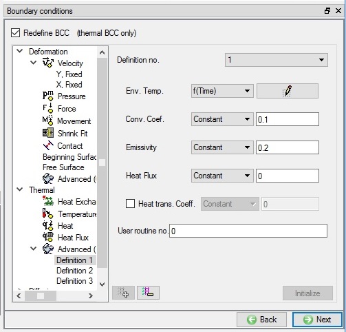
Redefined first Zone advanced thermal BCC for quenching
Similarly, redefine Convection coefficient as 0.24 and 0.48 and Emissivity as 0.4 and 0.6 respectively for the zone 2 (Definition 2) and zone 3 (Definition 3) respectively. Click ![]() until workpiece property page.
until workpiece property page.
Set Deformation property settings for Quenching
In Deformation property tab check the “EP Initial guess, use” checkbox and select Previous step solution option as shown in Fig. SRL1.24., click on ![]() Step controls branch in operation tree.
Step controls branch in operation tree.
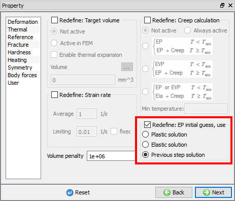
EP initial guess property settings for workpiece
Set Step, stopping and function time controls for Quenching
In Step Controls window, define Number of steps as 1200 steps, Time per step as 10 and step increment to save as 10 (See Fig. SRL1.25.).
Step controls settings for Quenching
Click on expert mode (![]() ) to view Advanced Simulation controls settings, to define 600 secs as process duration stopping control (See Fig. SRL1.26.).
) to view Advanced Simulation controls settings, to define 600 secs as process duration stopping control (See Fig. SRL1.26.).
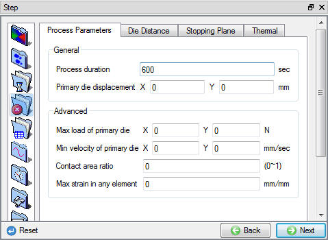
Stopping controls for quenching
Click on Advanced tab and under Variables tab Globaltime to use for function data and stopping criteria as shown in Fig. SRL1.27., Click ![]() to continue.
to continue.
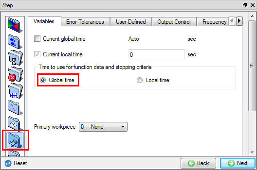
Time for function data settings in simulation control page
Click on ![]() to open the Heat transfer operation (See Fig. SRL1.28.), as database for this operation will be generated during simulation we set it up in batch mode.
to open the Heat transfer operation (See Fig. SRL1.28.), as database for this operation will be generated during simulation we set it up in batch mode.
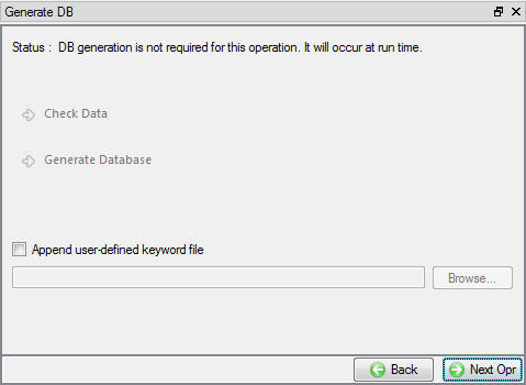
Database generation window for subsequent operations in batch mode
Operation3: Stress Relaxation (Creep)
In this operation, we will setup a heat transfer where the workpiece is heated to 700 C after quenching and soaked at that temperature for around 3 hours to relieve the retained stresses formed during quenching.
Select Heat Transfer Type for Stress Relaxation
For third operation, change the operation name to “Stress Relaxation” by double clicking on Operation name in Operation editor tab and select the Heat transfer type as ‘T**r ansfer through Air**’ (See Fig. SRL1.29.) and click ![]() to continue.
to continue.
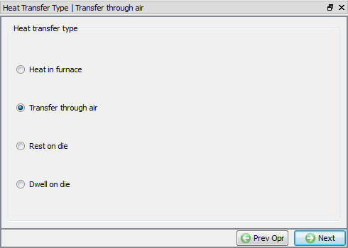
Heat transfer type selection page
Set Process Condition for Stress Relaxation
In process condition page set transfer time as 10800 sec, environment temperature as 700C and leave the default convection coefficient as it is as shown in Fig. SRL1.30.
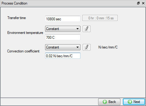
Process condition settings for stress relaxation operation
Set Simulation modes for Stress Relaxation
For third operation check the Deformation mode in addition to Heat transfer mode as we are interested to study creep during stress relaxation. Click ![]() until objects page.
until objects page.
Remove the additional objects for Stress Relaxation
We have Top die and Bottom die objects being added by default, select those objects and delete using ![]() button as we do not require them in this operation. Click on WorkpieceBCC branch in operation tree.
button as we do not require them in this operation. Click on WorkpieceBCC branch in operation tree.
Redefine Workpiece Boundary Conditions
Since Stress relaxation operation is carried on in an furnace and its convection coefficients and emissivity values are different than those used in Quenching operation, we will be changing them by checking Redefine BCC check box at the top. Select the thermal advanced BCC Definition 1, change the Convection coefficient to 0.01 and Emissivity to 0.1 keeping the previous Environment temperature definition as it is (See Fig. SRL1.31.)
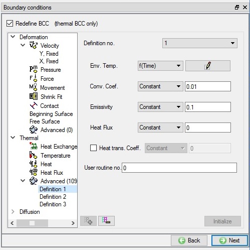
Redefined first Zone advanced thermal BCC for quenching
Similarly, for Zone2 (Definition 2) and Zone3 (Definition 3) redefine Convection coefficient as 0.024 and 0.048 and Emissivity to 0.2 and 0.3 respectively. Click ![]() until workpiece property page to set deformation property.
until workpiece property page to set deformation property.
Activating Creep calculation for Stress Relaxation
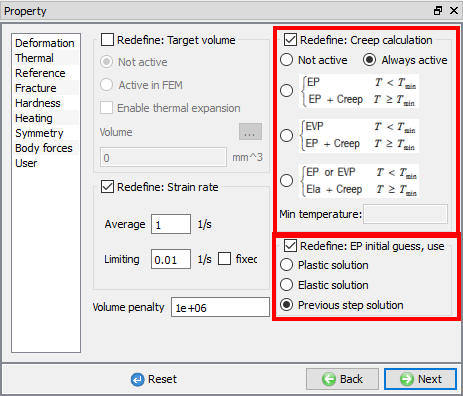
In Property page Deformation tab, check Creep calculation checkbox and select Active radio button as shown in Fig. SRL1.32. Under the “EP Initial guess, use”, select Previous step solution option. Click on ![]() Step branch in operation tree.
Step branch in operation tree.
Workpiece property page in stress relaxation operation
Set Step, function time and out put controls for Stress Relaxation
In Step Controls page define Number of steps as 1200, time increment per step as 10 sec and step increment to save as 10 steps (See Fig. SRL1.25.). Using expert mode, Click on Advanced tab and under Variables tab select the Global time to use for function data and stopping criteria as in previous operation. In Output controls tab under Strain tab, check the Creep strain checkbox to view creep strain output as shown in Fig. SRL1.33.
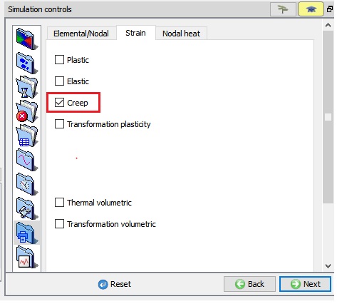
Output controls for stress relaxation operation
Click ![]() to step control page and Click on
to step control page and Click on ![]() to open the next Heat transfer operation.
to open the next Heat transfer operation.
Operation4: Cooling
In this operation, we will setup air cooling operation for workpiece to cool down its temperature from 700°C to room temperature for half an hour.
Select Heat Transfer Type for Cooling
For forth operation, change the operation name to “Cooling “ by double clicking on Operation name in Operation editor tab and select the Heat transfer type as ‘Transfer through Air ‘ and click ![]() to continue.
to continue.
Set Process Condition for Cooling
In process condition page, set transfer time as 1800 secs, environment temperature as 20°C and keep the default convection coefficient as it is as shown in Fig. SRL1.34. Click ![]() to continue.
to continue.

Process condition settings for cooling operation
Set Simulation modes for Cooling
In Simulation controls page, check the Deformation mode in addition to Heat transfer mode, as we are interested in residual stresses. Click ![]() until objects page.
until objects page.
Remove the additional objects for Cooling
We have Top die and Bottom die objects being added by default, select those objects and delete using ![]() button as we do not require them in this operation. Click on Step branch in operation tree, as no changes are required for Thermal BCC and same convection coefficients and emissivity values are applicable for air cooling operation also. If user does not redefine the BCC for read from DB object, BCC defined in previous operation will be used.
button as we do not require them in this operation. Click on Step branch in operation tree, as no changes are required for Thermal BCC and same convection coefficients and emissivity values are applicable for air cooling operation also. If user does not redefine the BCC for read from DB object, BCC defined in previous operation will be used.
Set Step controls and function time for Cooling
In Step Controls page, define number of steps as 1200 steps, time increment per step as 10 sec and step increment to save as 10 (See Fig. SRL1.25.). Using expert mode, Click on Advanced tab and under Variables tab select the Global time to use for function data and stopping criteria as in previous operation. Click ![]() to DB generation page and click on
to DB generation page and click on ![]() to open the next Boolean operation.
to open the next Boolean operation.
Operation5: Boolean
In this operation, we will be creating through hole at the centre of the workpiece.
Select Objects for Boolean
In objects page retain the Boolean object as Workpiece and Cutter object as Cutter and click ![]() until Cutter object geometry page.
until Cutter object geometry page.
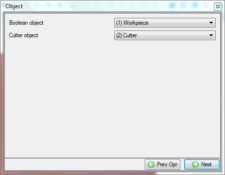
Objects page for boolean operation
Creating Cutter geometry for Boolean
In the Geometry page, select ![]() and define a cylinder with Radius of 3.25 mm, height of 9 mm (See Fig. SRL1.36.), click on
and define a cylinder with Radius of 3.25 mm, height of 9 mm (See Fig. SRL1.36.), click on ![]() button to close the Geometry primitive dialog. Click on
button to close the Geometry primitive dialog. Click on ![]() icon below object tree, using Offset positioning and move the Cutter with (X, Y) as (-0.255, -0.5). Click
icon below object tree, using Offset positioning and move the Cutter with (X, Y) as (-0.255, -0.5). Click ![]() until Boolean page.
until Boolean page.
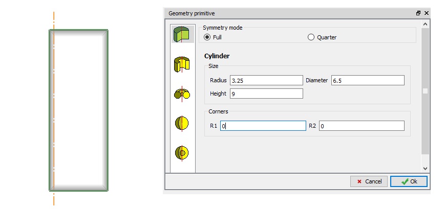
Cutter geometry primitive definition
Boolean preview can be seen only when previous operation is simulated, as this has been setup in batch mode we will not able to see the preview. Click ![]() until DB page and Click on
until DB page and Click on ![]() to open the next Machining Distortion operation.
to open the next Machining Distortion operation.
Operation6: Machining Distortion
We will setup machining distortion to study the residual stresses after machining.
Select Objects for Machining Distortion
In objects page retain the Workpiece as Workpiece from previous operation, add two fixtures and one pass, click on ![]() button and click
button and click ![]() to go to workpiece object page. (See Fig. SRL1.37.)
to go to workpiece object page. (See Fig. SRL1.37.)
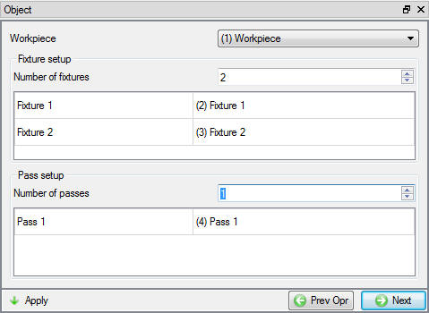
Objects selection page for machining distortion
Workpiece Selection page for Machining Distortion
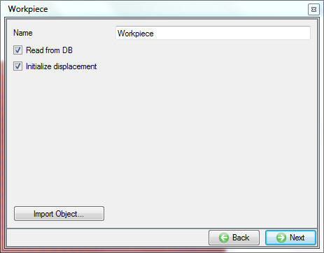
Check the Workpiece as Read from DB and Initialize displacement check boxes to initialize displacement to workpiece after reading from DB as shown in Fig. SRL1.38. click ![]() until Fixture 1 geometry page.
until Fixture 1 geometry page.
Machining distortion workpiece object page
Defining Fixture 1 for Machining Distortion
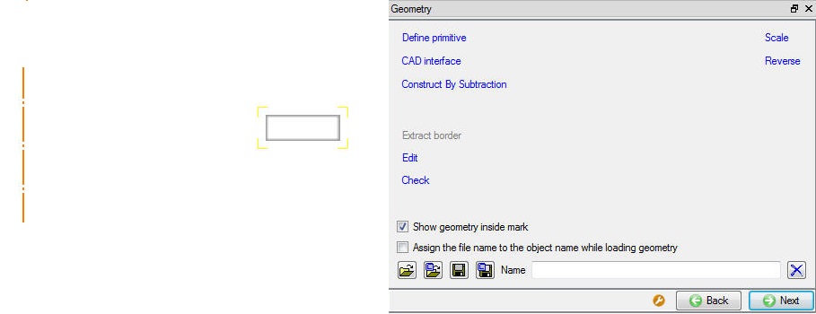
In Geometry window, load Stress_relaxation_Fixture1.geo geometry file from library using ![]() (Load geometry from library) option as shown in Fig. SRL1.39., Click Yes for the ‘User Library’ popup asking whether to use the installation labs folder path as default library location. The geometry is located in DEFORM installation folder \2D\Labs directory. Check the geometry using
(Load geometry from library) option as shown in Fig. SRL1.39., Click Yes for the ‘User Library’ popup asking whether to use the installation labs folder path as default library location. The geometry is located in DEFORM installation folder \2D\Labs directory. Check the geometry using ![]() option to make sure the geometry is OK. Then click
option to make sure the geometry is OK. Then click ![]() until fixture 2 geometry page.
until fixture 2 geometry page.
Fixture 1 geometry importing
Defining Fixture 2 for Machining Distortion
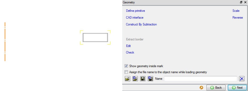
Similar toFixture 1 import the geometry Stress_relaxation_Fixture2.geo for Fixture 2 from library located in DEFORM installation folder \2D\Labs directory as shown in Fig. SRL1.40. Then click ![]() until Pass 1 geometry page
until Pass 1 geometry page
Fixture 2 geometry importing
Defining Pass for Machining Distortion
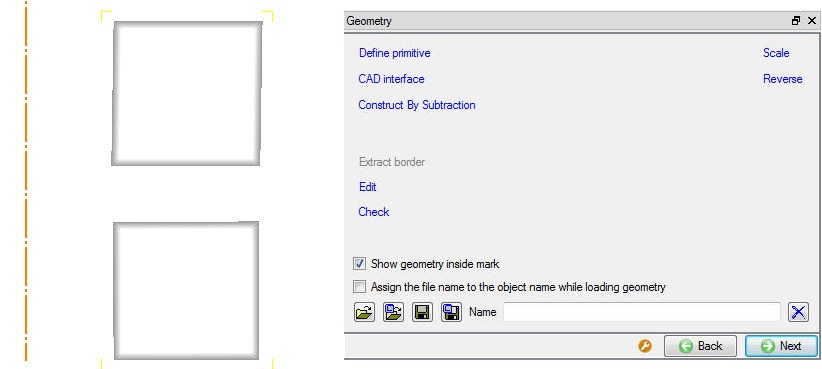
Similar to Fixture 1 import the geometry Stress_relaxation_Pass.geo for Pass1 from library located in DEFORM installation folder \2D\Labs directory as shown in Fig. SRL1.41. Then click ![]() until Scheduled positioning page.
until Scheduled positioning page.
Pass geometry importing
Scheduled positioning for Machining Distortion
As fixture 1 and fixture 2 need to positioned with respect to Read from DB object Workpiece, we will be using scheduled positioning during DB generation. Click on ![]() (Add) button and select the ‘Positioning object’ as Fixture 1, method as ‘Interference’ with respect to ‘Workpiece’ in the -Y direction. Similarly position Fixture 2 with respect to wprkpiece by interference in +Y direction by adding another scheduled positioning definition.(See Fig. SRL1.42.) Note that positioning details added in the scheduled positioning will be accounted prior to inter object data generation for this operation. No physical movement of the objects will be seen at this point. Click
(Add) button and select the ‘Positioning object’ as Fixture 1, method as ‘Interference’ with respect to ‘Workpiece’ in the -Y direction. Similarly position Fixture 2 with respect to wprkpiece by interference in +Y direction by adding another scheduled positioning definition.(See Fig. SRL1.42.) Note that positioning details added in the scheduled positioning will be accounted prior to inter object data generation for this operation. No physical movement of the objects will be seen at this point. Click ![]() to continue.
to continue.
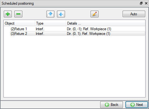
Scheduled position of fixtures
Schedule Inter-Object Contact Relationships for Machining Distortion
Select user type contact and click on ![]() button. It will add the relationships between the Fixture 1, Fixture 2 and Workpiece (See Fig. SRL1.43.). As the Fixtures are Rigid and Workpiece is plastic, Fixtures are considered as Master and Workpiece as Slave. Since the contact will initialize and generate while generating database. Click
button. It will add the relationships between the Fixture 1, Fixture 2 and Workpiece (See Fig. SRL1.43.). As the Fixtures are Rigid and Workpiece is plastic, Fixtures are considered as Master and Workpiece as Slave. Since the contact will initialize and generate while generating database. Click ![]() to continue, since the contacts will initialized and generated while generating database.
to continue, since the contacts will initialized and generated while generating database.
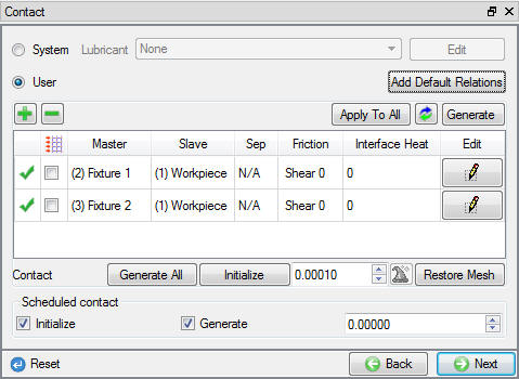
Contact relations for machining distortion
Pass Boolean Preview for Machining Distortion
In Simulation Preview page, we can see machining preview if previous operation is simulated, since we are setting up in batch mode machining preview will be shown by applying pass geometry to workpiece geometry defined in first operation. Click ![]() to continue.
to continue.
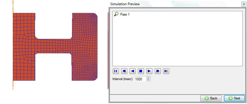
Pass boolean preview
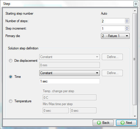
Set Step controls for Machining Distortion
In Step controls window define 2 steps at 1 sec/step and saving every step (See Fig. SRL1.45). Click ![]() until DB generation page..
until DB generation page..
Step controls for machining distortion
Running Simulation
Once the database has been generated switch to the Simulation mode by clicking on ![]() button above the operation tree. Click on the
button above the operation tree. Click on the ![]() action label to open the Run Options dialog as shown in Fig. SRL1.46. Use the default ContinueRun option to select “Continuefrom the last step ” option and then select the Simulation mode as Interactive radio button ** and click on
action label to open the Run Options dialog as shown in Fig. SRL1.46. Use the default ContinueRun option to select “Continuefrom the last step ” option and then select the Simulation mode as Interactive radio button ** and click on ![]() button to run the simulation.
button to run the simulation.
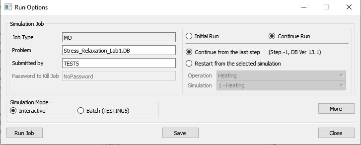
Run Simulation popup window
Monitor the progress of the simulation by looking at the Simulation Graphics, Simulation Message and Simulation Log tab, making sure that the ![]() option is checked. (See Fig. SRL1.47.)
option is checked. (See Fig. SRL1.47.)
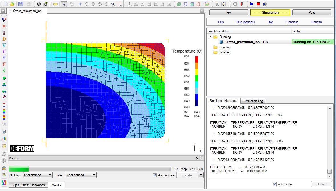
Simulation graphics
After completion of the all multiple operation in Simulation log file it gives the log message as “MULTIPLE OPERATION COMPLETED.”, then switch to Post tab to view the simulation results.
Post Processing
In post processor, Step list below the graphic area indicates step numbers available from the different operations simulated. A set of state variables available from the ‘Post’ menu can be used review the model response. Please note that for the first operation only the thermal state variables output for the workpiece is available as deformation calculation is activated only from second operation.
Plot the temperature and play steps from heating to cooling and observe the temperature distribution at the end of each operations as shown in Fig. SRL1.48.
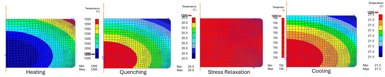
Temperature distribution at the end of each operations
Plot the stress and play steps in quenching, stress relaxation, cooling and machining distortion operations to observe the retained stress distribution at the end of each of these operations as shown in Fig. SRL1.49.
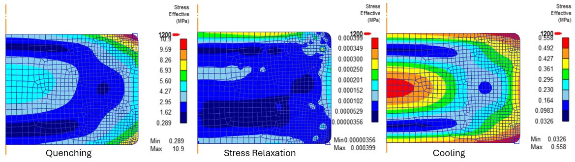
Retained stress distribution at the end of each operations
Plot Effective strain and check at the stress relaxation and check the strain at the end of stress relaxation and cooling operations as shown in Fig. SRL1.50.
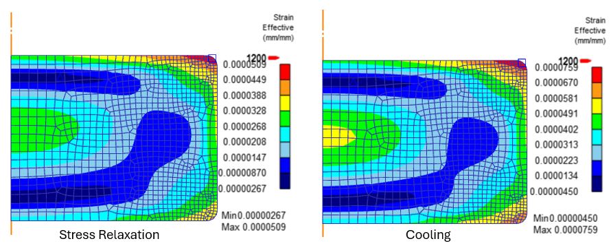
Effective strain at the end of Stress relaxation and cooling operations
Plot the Creep strain at the end of stress relaxation from state variable Strain- Creep branch as shown in Fig. SRL1.51.
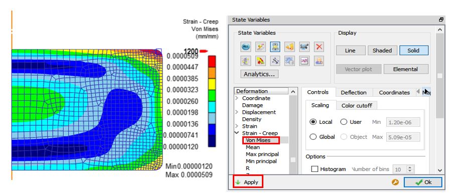
Creep strain at the end of stress relaxation operation
After boolean operation check how the workpiece looks as shown in Fig. SRL1.52.
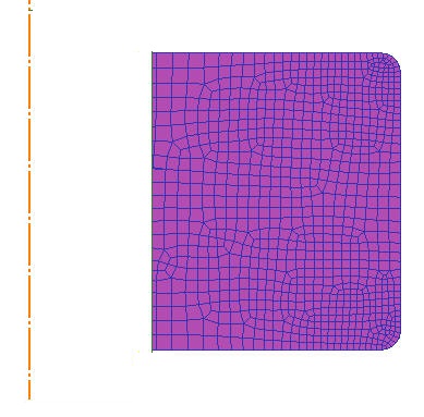
Workpiece After boolean
In machining distortion operation check how the workpiece mesh looks after loading, pass and unloading operations as shown in Fig. SRL1.53.
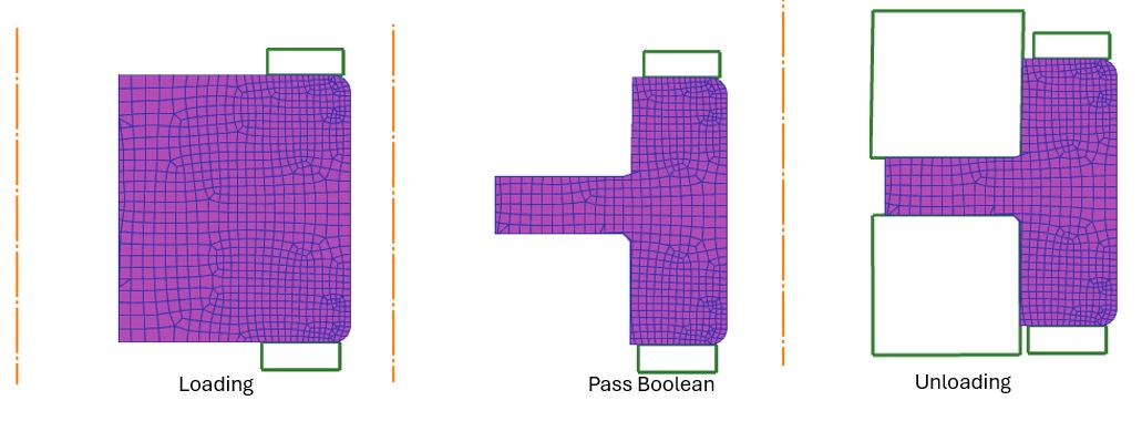
Workpiece during machining distortion
Plot the stress distribution during loading, pass and unloading operation as shown in Fig. SRL1.54.
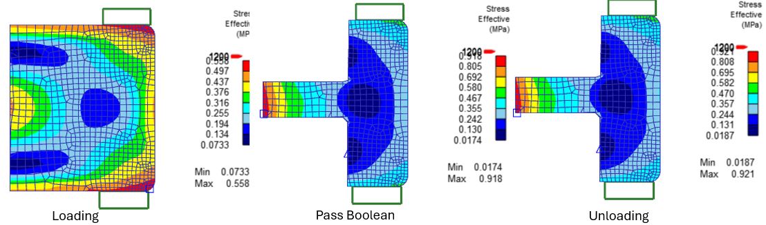
Stress distribution during machining distortion
Select 3D mode at the end of machining distortion to view results in 3D as shown in Fig. SRL1.55.
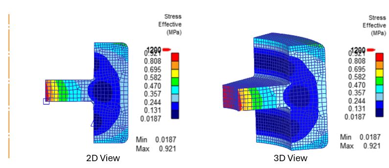
2d and 3d view of the workpiece at the end of machining distortion