9.3. Stopping Controls 
9.3.1. Process Duration (TMAX) [2D, 3D]
9.3.2. Primary Die Displacement (SMAX)
9.3.3. Minimum velocity of Primary Die (VMIN)
9.3.4. Maximum load of Primary Die (LMAX)
9.3.5. Maximum strain in any Element (EMAX)
9.3.6. Ring diameter measurement
9.3.7. Max outer diameter (ODMAX)
9.3.8. Min inner diameter (IDMIN)
9.3.9. Contact area ratio
9.3.10. Stop simulation when Folding
9.3.11. Stopping Window
9.3.12. Die distance
9.3.13. Stopping Plane (REFPOS)
9.3.14. Temperature stopping control
9.3.15. ALE Steady state (ALECON)
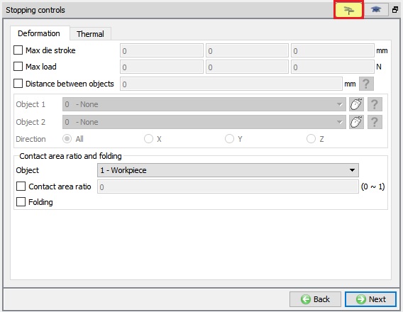
The stopping parameters determine the process time at which the simulation terminates. A simulation can be terminated based on the maximum number of time steps simulated the maximum accumulated elemental strain, the maximum process time, or maximum stroke, minimum velocity, or maximum load of the primary object. A simulation will be stopped when the condition of any of the stopping parameters are met. If a zero value is assigned to any of the termination parameters other than number of steps (NSTEP), the parameter will not be used. If no other stopping parameters are specified, the simulation will run until it has utilized all of the specified steps. (See Fig. 9.3.1. and Fig. 9.3.2.)
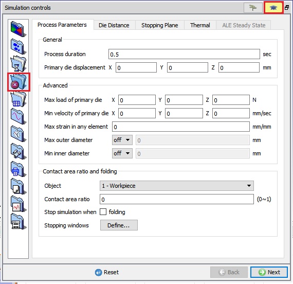
3D Process parameters for stopping a simulation
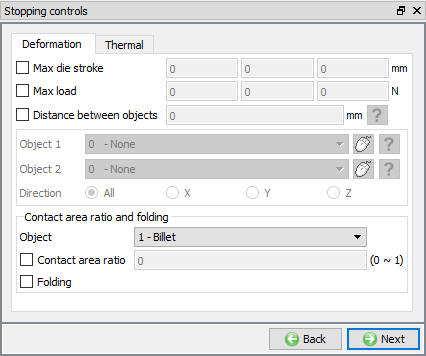
3D stopping controls in Guided mode
Process Duration (TMAX) [2D, 3D]
Terminates the simulation when the global process time (TMAX) reaches the value specified.
Primary Die Displacement (SMAX) [2D, 3D]
Terminates the simulation when the total displacement (SMAX) of the primary die reaches the specified value. The stroke value for the object is specified in the Object Movement tab.
Minimum velocity of Primary Die (VMIN) [2D, 3D]
Terminates the simulation when the X or Y or Z component of the primary die velocity reaches the respective X or Y or Z values of the VMIN.
This parameter is typically used when the primary object movement is under load control, or when the power limit (SPDLMT) parameter is enforced for a hydraulic press.
Maximum load of Primary Die (LMAX) [2D, 3D]
Terminates the simulation when the X or Y or Z load component of the primary die reaches the respective X or Y or Z value of LMAX. Typically used when the movement control of the primary object is velocity or user specified.
Maximum strain in any Element (EMAX) [2D, 3D]
This (EMAX) option terminates a simulation when the accumulated strain of any element reaches the specified value.
Ring diameter measurement [3D]
This option will be available only for the Ring rolling simulation type. When we turn on the Ring diameter measurement check box, we can select either “OD” or “ID” option to use the ring outer diameter or inner diameter as the stopping control. In Z input field, we can define the measurement location along the Z axis at which the diameter needs to be measured for the stopping control.
When we select “OD” option, we can observe the Max outer diameter option to define the outer diameter of the ring as the stopping control during simulation. Similarly, when we select “ID” option, we can observe the Min inner diameter option to define the inner diameter of the ring as the stopping control during simulation, see Fig. 9.3.3.. User needs to select the “>” from the drop-down menu to define the stopping control diameter value.
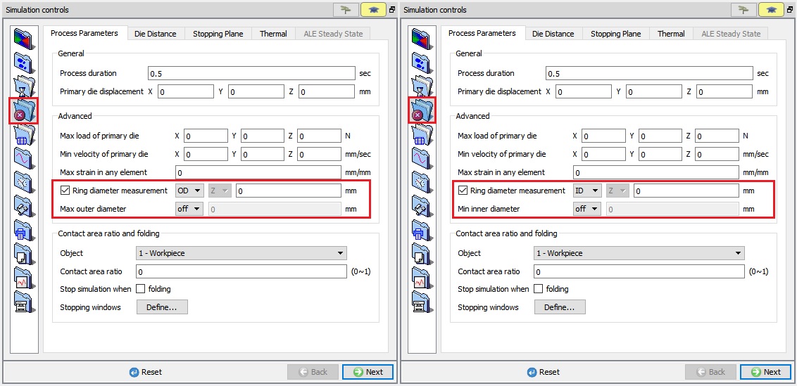
Ring diameter measurement option for ring rolling operation
Maximum outer diameter (ODMAX) [2D,3D]
This option terminates a simulation when the outer diameter of the workpiece exceeds the defined maximum outer diameter value. In 2D, this option is available only for Axisymmetric geometry type.
Option:
-
“off ”: when “off” option is selected, during simulation Maximum outer diameter stopping control will not been calculated.
-
“**< **“: when “ < “ option is selected, simulation will be terminated when the outer diameter of the workpiece is less than Max outer diameter value.
-
“> ” : when “ > “ option is selected, simulation will be terminated when the outer diameter of the workpiece is more than Max outer diameter value.
Min inner diameter (IDMIN)[2D3D]:
This option terminates a simulation when the inner diameter of the workpiece exceeds the defined minimum inner diameter value. In 2D, this option is available only for Axisymmetric geometry type.
Option:
-
“ off “ : When “off” option is selected, during simulation Minimum inner diameter stopping control will not been calculated.
-
“ < ” : When “ < “ option is selected, simulation will be terminated when the inner diameter of the workpiece is less than Min inner diameter value.
-
“ > “ : When “ > “ option is selected, simulation will be terminated when the inner diameter of the workpiece is more than Min inner diameter value.
Contact area ratio [2D,3D]
This option terminates a simulation when the contact area ratio exceeds the defined Contact area ratio value.
The contact area ratio ranges from 0-1, where 0 indicates no contact and 1 indicates complete contact. The centre line in 2D and symmetry planes in 3D are excluded from the contact area ratio calculations.
Stop simulation when Folding [2D, 3D]
This option terminates a simulation when the fold is detected in the defoming object mesh.
Stopping Window [2D, 3D]:
User can use a Stopping Window option to specify the location over the workpiece to check the die fill/contact ratio or fold. “Contact area ratio” and “Fold” options are available under “Stop when” pulldown list. (See Fig. 9.3.4.).
When “Contact area ratio” is selected, if the workpiece surface area inside the window region reaches the defined contact ratio criteria then FEM simulation will stop.
When Fold is selected, if fold is detected on the workpiece surface inside the window region then FEM simulation will stop.
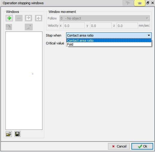
Stopping plane window
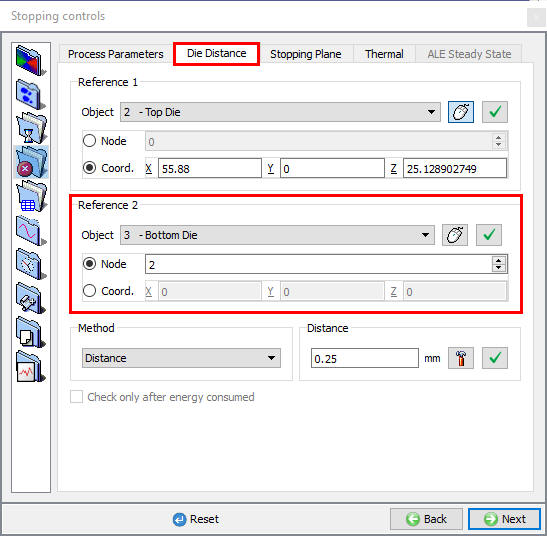
Die Distance [2D, 3D]
Terminates a simulation when the distance between reference points (MDSOBJ) on two objects reaches the specified distance. Stopping distance must be used in conjunction with the reference point (REFPOS) definition Die Distance window.
From V12.0.2, for the reference objects if the reference points is defined (in Object Properties) we can observe the ![]() status and for the Reference object if reference object is not defined then we can observe the
status and for the Reference object if reference object is not defined then we can observe the ![]() status in Die-Distance tab as shown in Fig. 9.3.5.
status in Die-Distance tab as shown in Fig. 9.3.5.
For read from DB reference object (in successive operation), if the reference points is defined, then we can observe the ![]() status and for the Reference object if reference object is not defined then we can observe the
status and for the Reference object if reference object is not defined then we can observe the ![]() status in Die-Distance tab as shown in Fig. 9.3.6.
status in Die-Distance tab as shown in Fig. 9.3.6.
(a)
(b)
Stopping distance based on die distance; (a) Defining the first reference point (b) Defining the second reference point
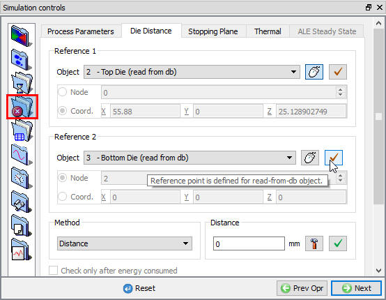
Die- Distance Stopping Controls Expert mode window for read from DB object.
Defining a stopping distance,
- Select which object is to be used for Reference 1.
- Select either node or co-ordinate for Reference 1 object and then pick the appropriate point on reference 1 object as shown in Fig. 9.3.5..(a).
- Select which object is to be used for Reference 2.
- Select either node or co-ordinate for Reference 2 object and then pick the appropriate point on reference 2 object as shown in Fig. 9.3.5.(b).
- Set the distance method and the distance at which to stop the simulation.
Check only after energy consumed : This option is newly added in v12.1.1, check only after energy consumed option will get activates only for energy based movement type (Hammer and Screw press movement). When user turned on the “Check only after energy consumed” check box, during simulation Die distance stopping criteria will be calculated only when energy is fully consumed instead end of each step.
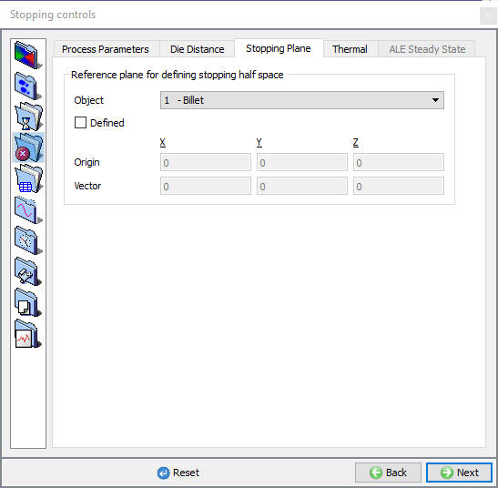
Stopping Plane (REFPOS) [2D, 3D]
Typically used in the models like transient rolling process, user can define a plane in space, and have the simulation terminate once the work piece completely crosses this plane. (See Fig. 9.3.7.)
Stopping distance based on stopping plane
From v13.0, we can define the Reference plane data separately for each deformable object.
To define the Reference plane stopping controls, first select the reference object from pulldown list and check the Defined check box and then define the Origin value (to define the location of the plane) and Vector data (to define the normal for the plane).
We must define the Vector value w.r.t the reference object movement direction.
User can also click on the object in display region to select deformable object and its origin data.
When the reference object whole region crosses the defined plane during simulation, then the simulation terminates with below message.
“ PROGRAM STOPPED!
Stopping plane: All nodes of Object 1 has exited the die/roll.”
Note : Only Plastic and Elasto-plastic objects will be listed under Object list for Stopping plane stopping controls.
For example:
In 2D rolling operation,
-
Define the Stopping Plane data by selecting “Workpiece” object in list and by checking “Defined” check box.
-
Then define the origin as 0, 0, to define the location of the plane.
-
Now, define the Vector as “-1” in X field (to define the normal w.r.t stopping plane) as shown in below Fig. 9.3.8..
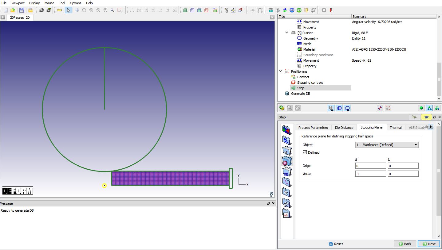
Defining 2D Stopping Plane in rolling operation
Temperature stopping control [2D, 3D]
This thermal stopping control used to control the temperature of objects in the process. User can define min and max temperature as a stopping control in the objects level (see Fig. 9.3.9.). This can be accessed from Object data definition window Object Properties- Thermal tab.
Object
Reference object for thermal stopping controls will be selected under Object list.
Stopping Method
None : Applies no thermal stopping controls
Any Node : Simulation stops when any node in the billet reaches the specified value.
All Nodes : Simulation stops when all the nodes in the billet reach the specified value.
Selected Node :Simulation stops when specified node in the billet reaches the specified value.
Average All Nodes : Simulation stops when average temperature of all the nodes in the billet reaches the specified value.
Average surface Temp +Max. Temp : Simulation stops when average temperature of all the nodes
on the surface of billet + Maximum temperature in the billet reaches the specified value.
Temperature Range
Apart from single value a range of temperature also can be used to stop the simulation.
Stop when temperature is outside range : Simulation stops when the temperature value is outside the specified range.
Stop when temperature is inside range : Simulation stops when the temperature value is inside the specified range.
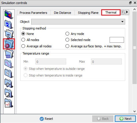
Stopping control based on thermal
ALE Steady state (ALECON) [3D]
From DEFORM V12, user can define ALE steady state (ALECON) stopping criteria for ALE rolling operation in Stopping controls - ALE Steady state stopping control tab. (See Fig. 9.3.10.)
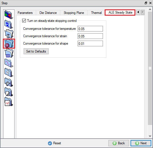
ALE Steady state stopping criteria
Related Topics:
9.1. Simulation type Settings
9.2. Defining Step
9.4. Remesh Criteria
9.5. Solver Settings
9.6. Process Conditions
9.7. Advanced Options
9.8. Control Files
9.9. Thermomechanical variables