Arc Welding
In this lab we will demonstrate how to setup simple Arc welding operation.
1.1. Creating a New Problem
1.2. Adding Forming Operation
1.3. Simulation Controls
1.4. Material list
1.5. Object
1.5.1. Workpiece
1.5.1.1. Bottom Plate Geometry
1.5.1.2. Bottom Plate Mesh
1.5.1.3. Bottom Plate Material
1.5.1.4. Bottom Plate Boundary condition
1.5.1.5. Initialize Volume fraction for Bottom Plate
1.5.2. Top Die
1.5.2.1. Top Plate Geometry
1.5.2.2. Top Plate Mesh
1.5.2.3. Top Plate Material
1.5.2.4. Top Plate Boundary condition
1.5.2.5. Initialize Volume fraction for Top Plate
1.5.3. Bottom Die
1.5.3.1. Bead 1 Geometry
1.5.3.2. Bead 1 Mesh
1.5.3.3. Bead 1 Material
1.5.3.4. Bead 1 Boundary condition
1.5.3.5. Initialize Volume fraction and Additive manufacturing for Bead 1
1.6. Contact
1.7. Stopping Controls
1.8. Step Controls
1.9. Generate DB
1.10. Running Simulation
1.11. Post Processing
Creating a New Problem
On a Windows machine, go to the ![]() button select DEFORM-v1x.xxx (.xxx indicates version number E.g. v14.0.2) and select DEFORM GUI Main v1x.x from the menu. The DEFORM GUI Main window will appear, as shown in Fig. AWL1.1.
button select DEFORM-v1x.xxx (.xxx indicates version number E.g. v14.0.2) and select DEFORM GUI Main v1x.x from the menu. The DEFORM GUI Main window will appear, as shown in Fig. AWL1.1.
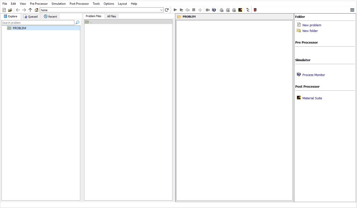
QT4 GUI Main window
Create a new problem either by selecting File![]() New Problem or by clicking the New Problem
New Problem or by clicking the New Problem ![]() icon. The Problem Setup window will appear as shown in Fig. AWL1.2. Select “ Integrated Manufacturing Process “ radio button and unit system as “SI “ radio button in unit field. Define Problem Name as “ ARC_WELDING_LAB “ and make sure the “Show option dialog” check box is turned on (if we do not turn on the “Show option dialog ” check box, then we will not get the New Project dialog in MO UI). Then click on
icon. The Problem Setup window will appear as shown in Fig. AWL1.2. Select “ Integrated Manufacturing Process “ radio button and unit system as “SI “ radio button in unit field. Define Problem Name as “ ARC_WELDING_LAB “ and make sure the “Show option dialog” check box is turned on (if we do not turn on the “Show option dialog ” check box, then we will not get the New Project dialog in MO UI). Then click on ![]() button to open a new Problem using the Deform Integrated Manufacturing Process.
button to open a new Problem using the Deform Integrated Manufacturing Process.
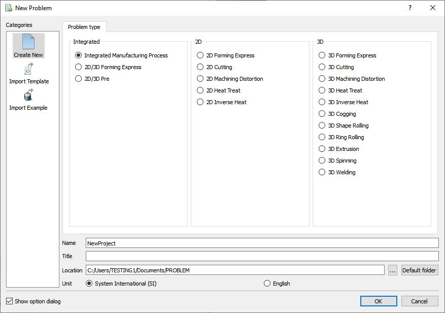
New Problem page
Multiple operation wizard will open with the New Project dialog, at this point user will be prompted to specify a project name (system will create a separate folder with this project name) and title for this session. In this session we will use “ARC_WELDING_LAB “ as the project name. Click on ![]() to continue to open the operation.
to continue to open the operation.
Adding Forming Operation
Add 3D Forming operation from the Explorer Operations list. Add the operation by clicking on ![]() button available next to [3D] Forming or can also be added by drag and drop into the Operation editor (See Fig. AWL1.3.). When we add the Forming operation, process settings window will open by default.
button available next to [3D] Forming or can also be added by drag and drop into the Operation editor (See Fig. AWL1.3.). When we add the Forming operation, process settings window will open by default.
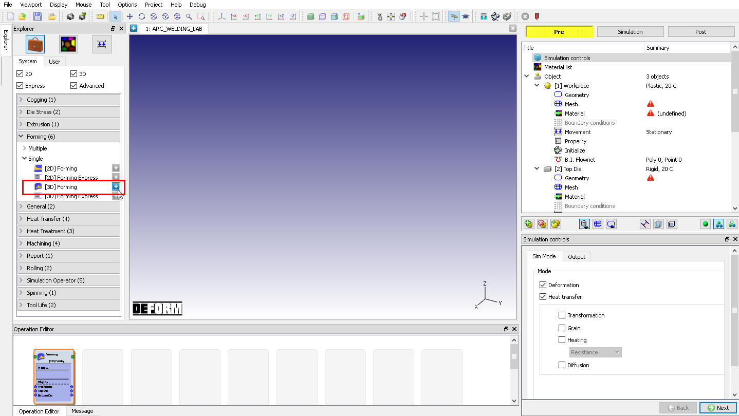
Adding 3D Forming operation from Explorer
Simulation Controls
Check “Deformation “, “Heat Transfer “ and “Transformation “ mode check boxes as show in Fig. AWL1.4. Click ![]() to Material page.
to Material page.
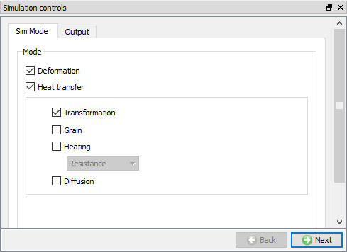
Simulation Controls - Guided mode
Material list
Using ![]() button import material from “ ARC_Welding_Material.key “ file from/3D/ LABS / Arc_Welding folder path. Imported material is displayed as shown in below Fig. AWL1.5. Click
button import material from “ ARC_Welding_Material.key “ file from/3D/ LABS / Arc_Welding folder path. Imported material is displayed as shown in below Fig. AWL1.5. Click ![]() until object page.
until object page.
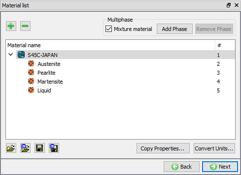
Material list
Object
For this lab we need three objects, in the list keep all three objects, Click ![]() to Workpiece page.
to Workpiece page.
Workpiece
In Workpiece page, change the object name to “Bottom Plate “, object type as “Elasto-Plastic “ and select “Mixed (Tet mesh) “ option from drop - down menu. Keep the object temperature as 20°C as shown in Fig. AWL1.6.
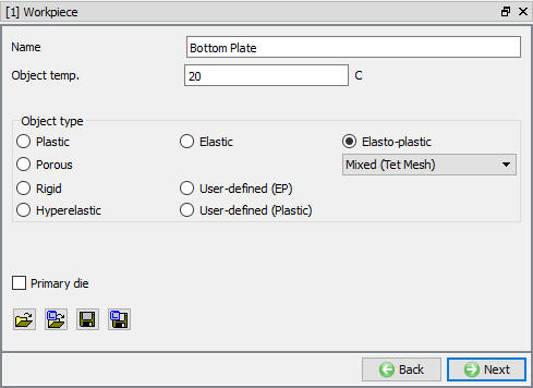
Bottom Plate General page
Bottom Plate Geometry
In Geometry page, using ![]() button import Bottom_Plate.stl file from /3D/ LABS/Arc_Welding folder (see Fig. AWL1.7.), after importing geometry use
button import Bottom_Plate.stl file from /3D/ LABS/Arc_Welding folder (see Fig. AWL1.7.), after importing geometry use ![]() action label to check the Geometry and click
action label to check the Geometry and click ![]() to close the popup.
to close the popup.
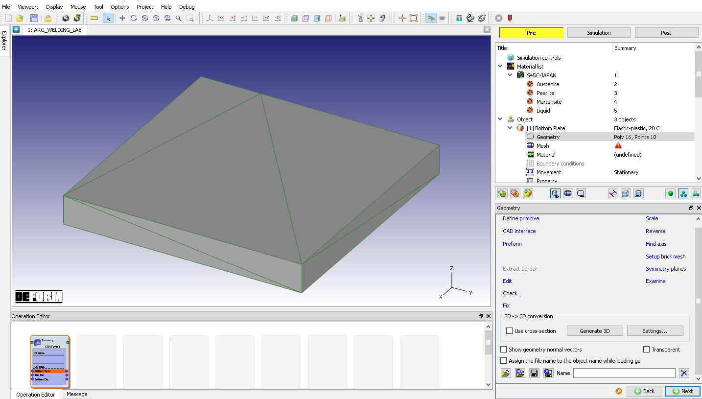
Bottom Plate Geometry page
Click on Symmetry planes , add planar symmetry plane on +X direction surface of Bottom Plate, similarly add-X Direction surface and -Y direction surface as shown in Fig. AWL1.8. Click on ![]() to close the symmetry planes and click
to close the symmetry planes and click ![]() to Mesh page.
to Mesh page.
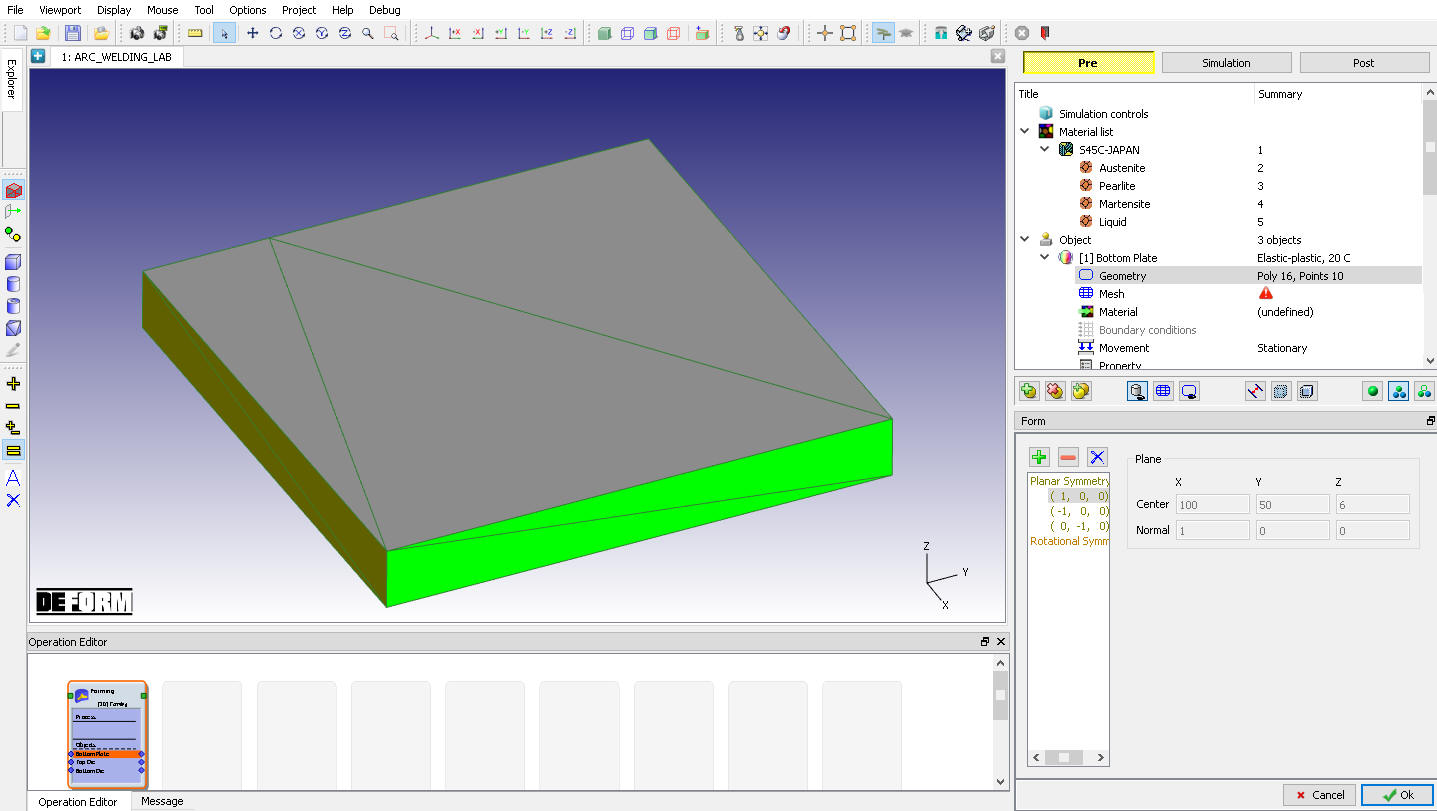
Symmetry planes page
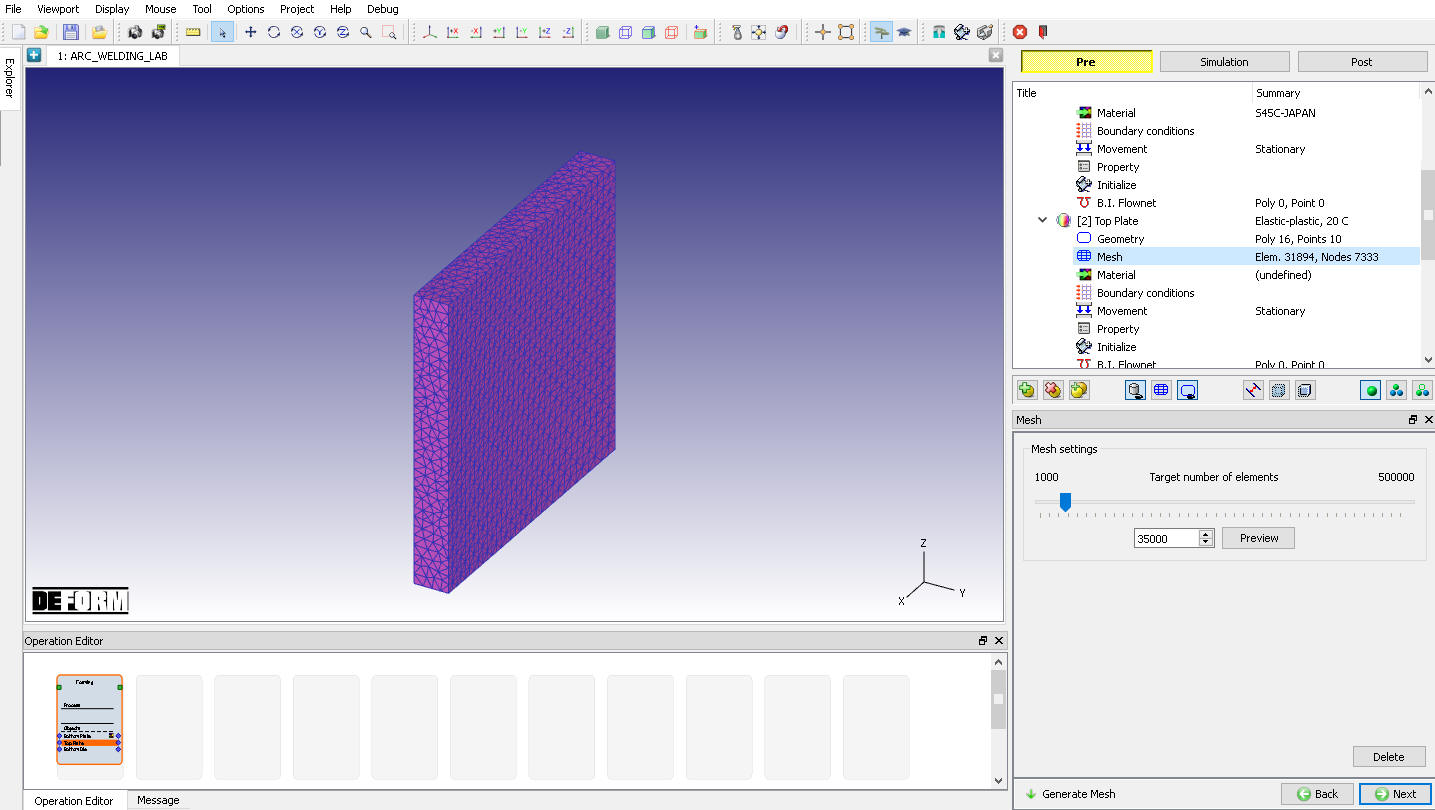
Bottom Plate Mesh
Define the Number of Elements as 35000 and click on ![]() and click Yes in “Default Boundary Conditions” popup to assign default boundary condition for Bottom plate. Generated mesh for Bottom plate looks like as shown in Fig. AWL1.9. Click
and click Yes in “Default Boundary Conditions” popup to assign default boundary condition for Bottom plate. Generated mesh for Bottom plate looks like as shown in Fig. AWL1.9. Click ![]() to Material page.
to Material page.
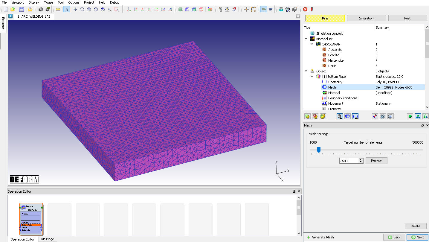
Bottom Plate Mesh page
Bottom Plate Material
Assign “S45C-JAPAN “ material from list for Bottom Plate as shown in Fig. AWL1.10. Click ![]() to Boundary Condition page.
to Boundary Condition page.
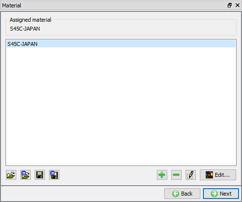
Bottom Plate Material page
Bottom Plate Boundary condition
Observe the default Symmetry BCC data assigned to Bottom plate while generating mesh, Symmetry BCC will be assigned to +X direction, -X direction and -Y direction surfaces as we defined in Geometry - Planar symmetry page (See Fig. AWL1.11..)
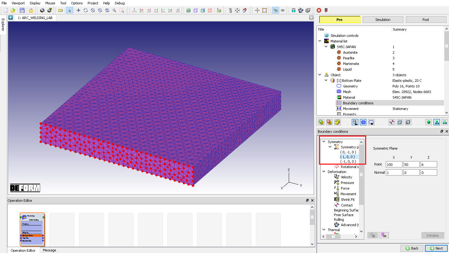
Assigned Symmetry plane BCC on +X direction surface
We will fix the bottom surface of the Bottom plate, this can be done by selecting Velocity option from BCC tree and Z Direction radio button with 0 mm/sec velocity. Click on ![]() to finish the assignment. Assigned Velocity BCC is displayed as shown in Fig. AWL1.12.
to finish the assignment. Assigned Velocity BCC is displayed as shown in Fig. AWL1.12.
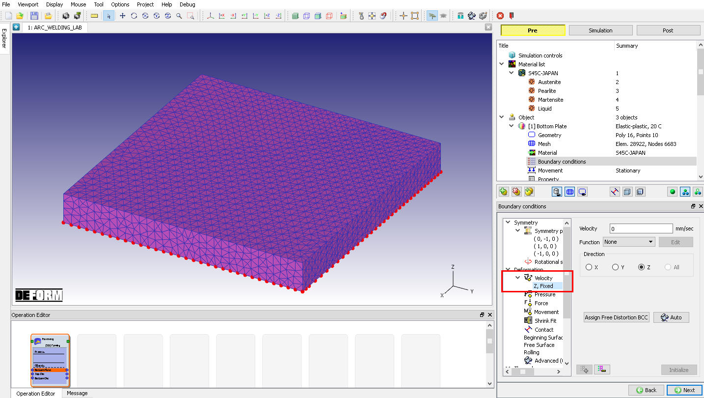
Assigned Velocity BCC on Bottom surface of the Bottom Plate
By default, Heat Exchange with environment BCC will be assigned to entire outer surface except symmetry plane as during meshing as shown in Fig. AWL1.13. Click ![]() to Movement page.
to Movement page.
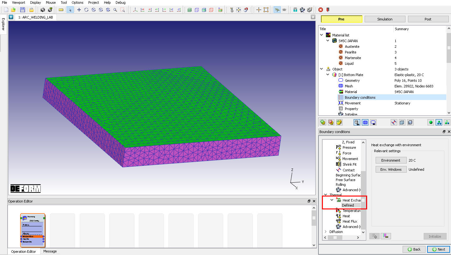
Assigned Heat exchange with Environment BCC on Bottom surface of the Bottom Plate
Initialize Volume fraction for Bottom Plate
Click on ![]() to access the element dialog to initialize the volume fraction. On the item list window click ‘Microstructure’
to access the element dialog to initialize the volume fraction. On the item list window click ‘Microstructure’ ![]() ‘Phase’ and then choose ‘Pearlite ’ and click on
‘Phase’ and then choose ‘Pearlite ’ and click on ![]() to ‘Initialize Element Data’. Enter 1 in value field with default settings, then click on
to ‘Initialize Element Data’. Enter 1 in value field with default settings, then click on ![]() and close the window. Click on
and close the window. Click on ![]() and observe the assigned Pearlite phase for all elements (See Fig. AWL1.14.). Click
and observe the assigned Pearlite phase for all elements (See Fig. AWL1.14.). Click ![]() to close Element dialog. Click
to close Element dialog. Click ![]() until Top Die page.
until Top Die page.
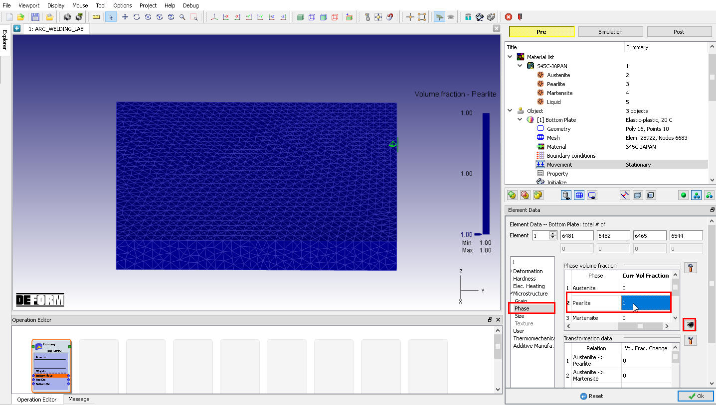
Element Dialog – Initialization of Phase Volume for Bottom Plate
Top Die
In Top die page, change the object name to “Top Plate “, select object type as “Elasto-Plastic “ and select “Mixed (Tet mesh) “ option from drop - down menu. Keep the object temperature as 20°C as shown in Fig. AWL1.15.
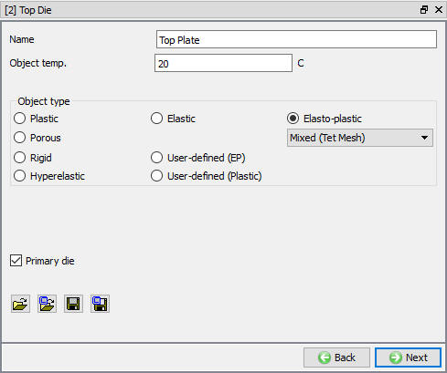
Top Plate General page
Top Plate Geometry
In Geometry page, using ![]() button import Top_Plate.stl file from /3D/ LABS/Arc_Welding folder, after importing geometry, use
button import Top_Plate.stl file from /3D/ LABS/Arc_Welding folder, after importing geometry, use ![]() action label to check the Geometry and click
action label to check the Geometry and click ![]() to close Check geometry popup. Click on Symmetry planes , add button at planar symmetry plane on +X direction surface of Top Plate, similarly add -X direction surface and -Y direction surface as shown in Fig. AWL1.16. Click on
to close Check geometry popup. Click on Symmetry planes , add button at planar symmetry plane on +X direction surface of Top Plate, similarly add -X direction surface and -Y direction surface as shown in Fig. AWL1.16. Click on ![]() to close the Symmetry planes and click
to close the Symmetry planes and click ![]() to Mesh page.
to Mesh page.
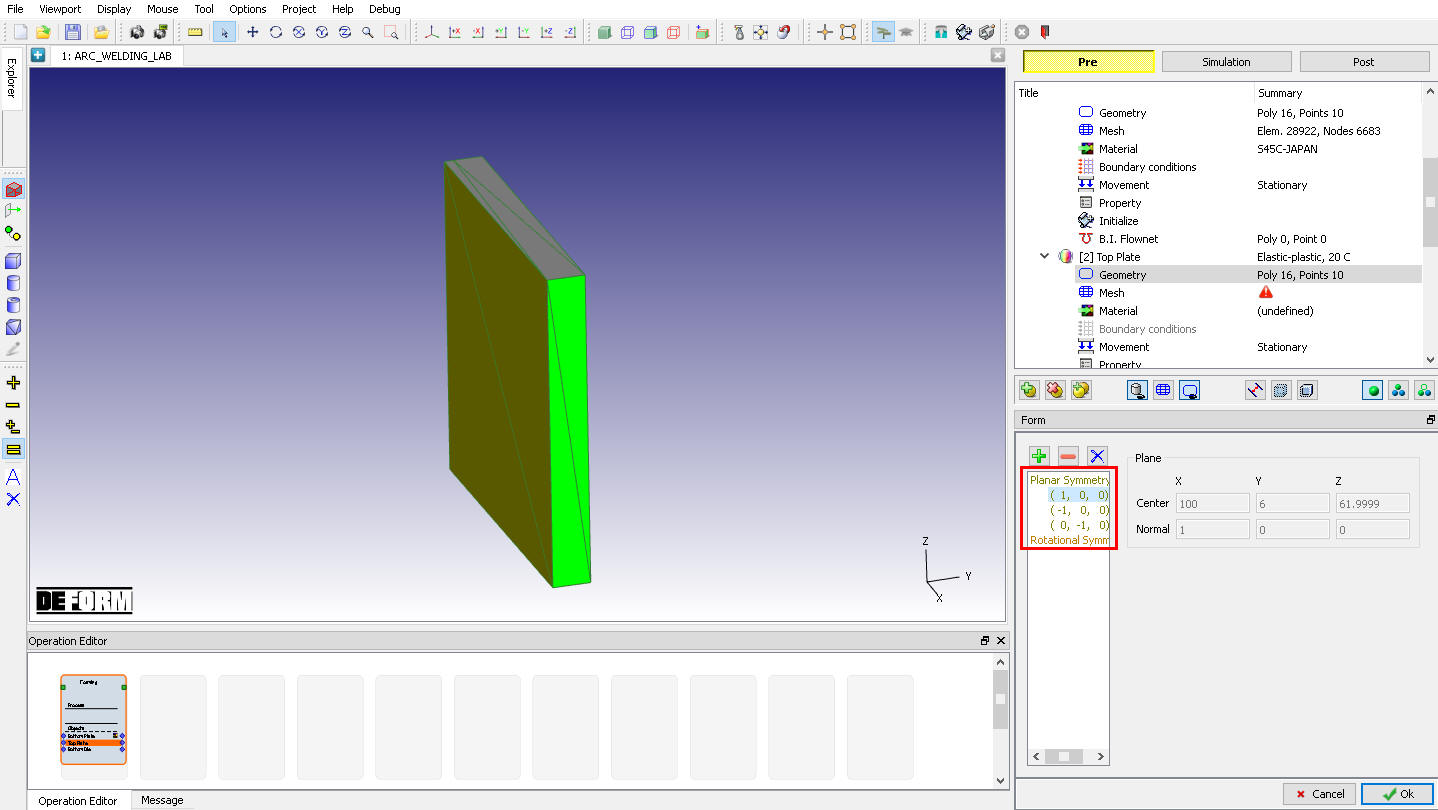
Top Plate Geometry page
Top Plate Mesh
Define the Number of Elements as 35000 and click on ![]() , click Yes in “Default Boundary Conditions” popup to assign default boundary condition for Top plate. Generated mesh for Top Plate looks like as shown in Fig. AWL1.17. Click
, click Yes in “Default Boundary Conditions” popup to assign default boundary condition for Top plate. Generated mesh for Top Plate looks like as shown in Fig. AWL1.17. Click ![]() to Material page.
to Material page.
Top Plate Mesh page
Top Plate Material
Assign “S45C-JAPAN “ material from list for Top Plate. Click ![]() to Boundary Condition page.
to Boundary Condition page.
Top Plate Boundary condition
Observe the default Symmetry BCC data assigned to Top plate while generating mesh, Symmetry BCC will be assigned to +X direction, -X direction and -Y direction surfaces as we defined in Geometry - Planar symmetry page (See Fig. AWL1.18.).
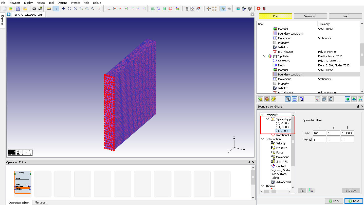
Assigned Symmetry plane BCC on +X direction surface
By default, Heat Exchange with environment BCC will be assigned to entire outer surface except symmetry planes during remesh as shown in Fig. AWL1.19. Click ![]() to Movement page.
to Movement page.
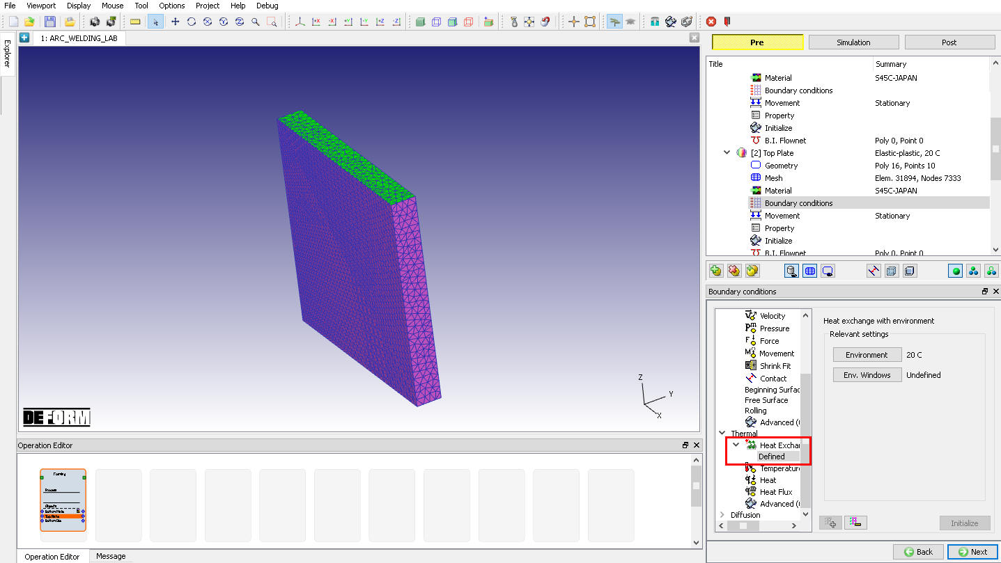
Assigned Heat Exchange with environment BCC on the Top Plate
Initialize Volume fraction for Top Plate
Click on ![]() to access the element dialog to initialize the volume fraction. On the item list window click ‘Microstructure’
to access the element dialog to initialize the volume fraction. On the item list window click ‘Microstructure’ ![]() ‘Phase’ and then choose ‘Pearlite ’ and click on
‘Phase’ and then choose ‘Pearlite ’ and click on ![]() to ‘Initialize Element Data’. Type 1 in value field with default settings, then click on
to ‘Initialize Element Data’. Type 1 in value field with default settings, then click on ![]() , then close the window. Click on
, then close the window. Click on ![]() and observe the assigned Pearlite phase for all elements (See Fig. AWL1.20.). Click
and observe the assigned Pearlite phase for all elements (See Fig. AWL1.20.). Click ![]() to close Element dialog. Click
to close Element dialog. Click ![]() until Bottom Die page.
until Bottom Die page.
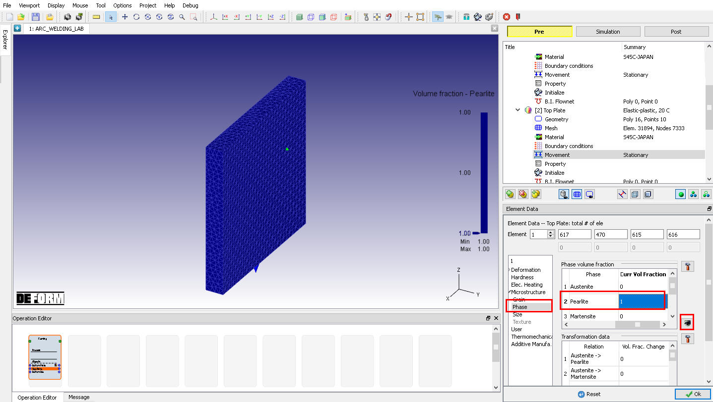
Element Dialog – Initialization of Phase Volume for Top Plate
Bottom Die
In Bottom Die page, change the object name to “Bead 1 “, select object type as “Elasto-Plastic “ and select “Mixed (Tet mesh) “ option from drop - down menu. Keep the object temperature as 20°C as shown in Fig. AWL1.21.
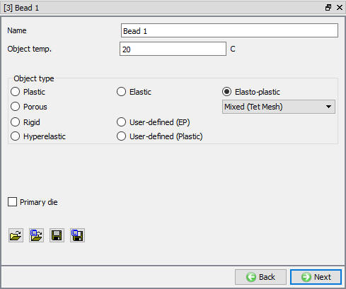
Bead 1 General page
Bead 1 Geometry
In Geometry page, using ![]() button import Bead1.stll file from /3D/ LABS/Arc_Welding folder. After importing geometry use
button import Bead1.stll file from /3D/ LABS/Arc_Welding folder. After importing geometry use ![]() action label to check the Geometry and click
action label to check the Geometry and click ![]() to close Check geometry popup. Click on Symmetry planes , add planar symmetry plane on +X direction surface of Bead 1, similarly add -X Direction surface as shown in Fig. AWL1.22. Click on
to close Check geometry popup. Click on Symmetry planes , add planar symmetry plane on +X direction surface of Bead 1, similarly add -X Direction surface as shown in Fig. AWL1.22. Click on ![]() to close the Symmetry planes and click
to close the Symmetry planes and click ![]() to Mesh page.
to Mesh page.
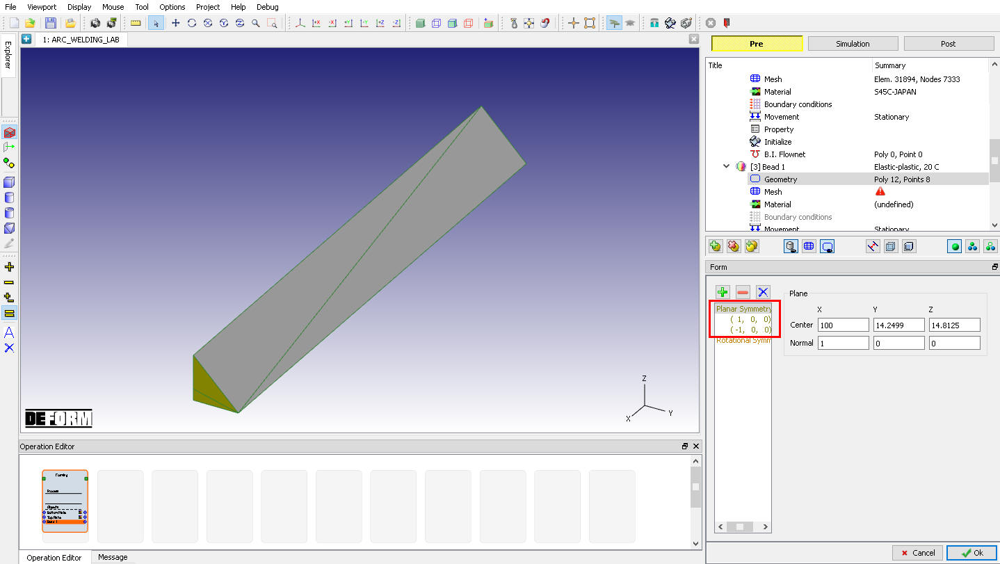
Bead 1 Geometry page
Bead 1 Mesh
Switch to Expert mode by clicking on ![]() icon, define the Number of Element as 40000 and Size ratio as 1 then click on
icon, define the Number of Element as 40000 and Size ratio as 1 then click on ![]() and click Yes in “Default Boundary Conditions” popup to assign default boundary condition for Bead 1. Generated mesh for Bead 1 is displayed as shown in Fig. AWL1.23. Click
and click Yes in “Default Boundary Conditions” popup to assign default boundary condition for Bead 1. Generated mesh for Bead 1 is displayed as shown in Fig. AWL1.23. Click ![]() to Material page.
to Material page.
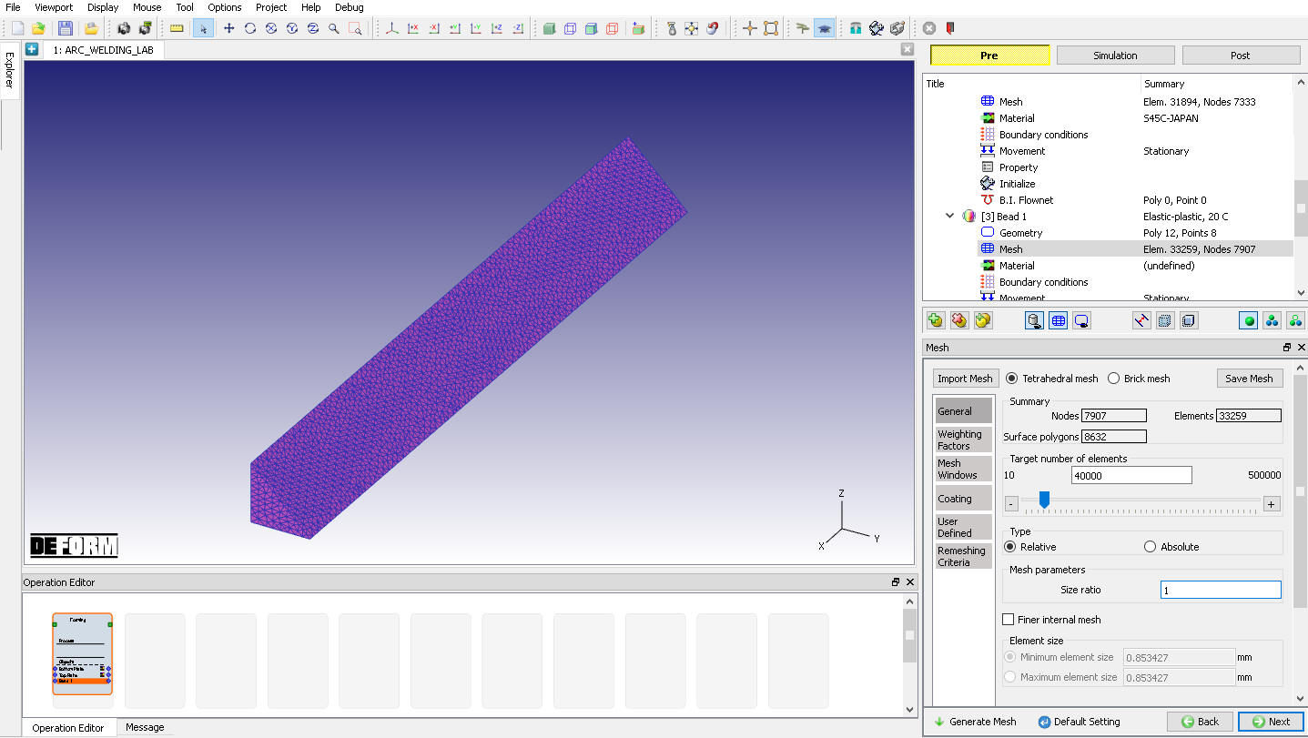
Bead 1 Mesh page
Bead 1 Material
Assign “S45C-JAPAN “ material from list for Bead 1. Click ![]() to Boundary Condition page.
to Boundary Condition page.
Bead 1 Boundary condition
Observe the default Symmetry BCC data assigned to Bead 1 while generating mesh, Symmetry BCC will be assigned to +X direction and -X direction surfaces as we defined in Geometry - Planar symmetry page (See Fig. AWL1.24.).
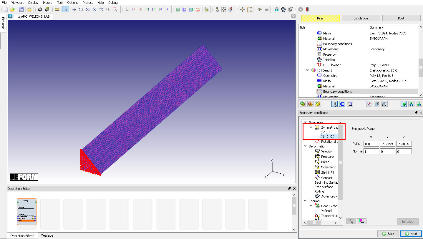
Assigned Symmetry plane BCC on +X direction surface
By default, Heat Exchange with environment BCC will be assigned to entire outer surface except symmetry planes as shown in Fig. AWL1.25. Click ![]() to Movement page.
to Movement page.
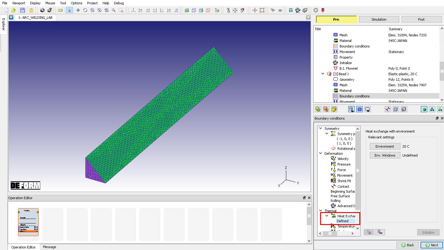
Assigned Heat Exchange with environment BCC for Bead 1
Initialize Volume fraction and Additive manufacturing for Bead 1
Click on ![]() to access the element dialog to initialize the volume fraction. On the item list window click ‘Microstructure ’
to access the element dialog to initialize the volume fraction. On the item list window click ‘Microstructure ’ ![]() ‘Phase’. Choose ‘Pearlite ’ and then click on
‘Phase’. Choose ‘Pearlite ’ and then click on ![]() to ‘Initialize Element Data’. Type 1 in value field with default settings, then click on
to ‘Initialize Element Data’. Type 1 in value field with default settings, then click on ![]() and close the pop-up window. Click on
and close the pop-up window. Click on ![]() and observe the assigned Pearlite phase for all elements (See Fig. AWL1.26.).
and observe the assigned Pearlite phase for all elements (See Fig. AWL1.26.).
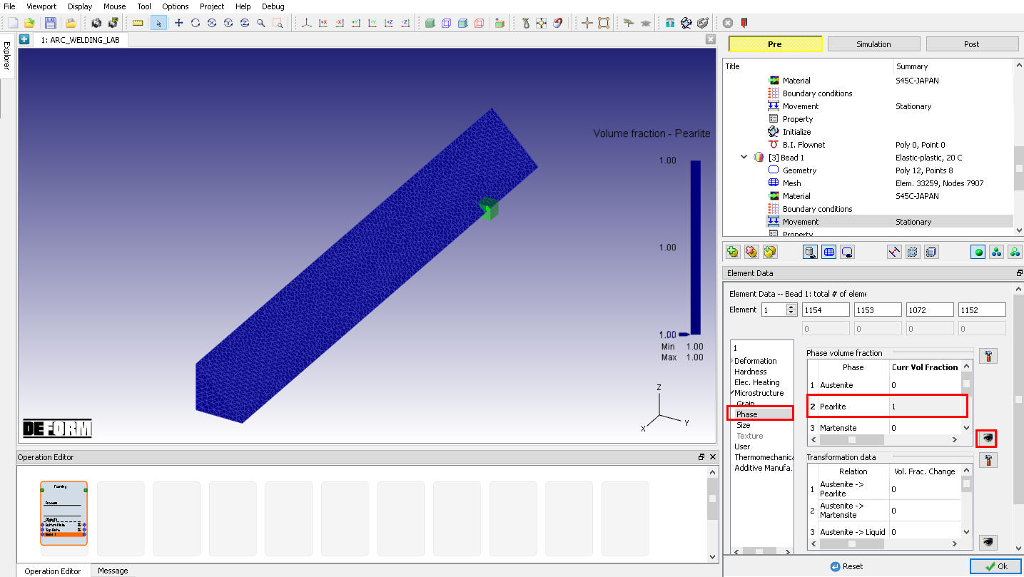
Element Dialog – Initialization of Phase Volume for Bead 1
On the list click “Additive Manufacturing “, click on Element layer ![]() to ‘Initialize Layer ID’. Enter 1 in value field with default settings, then click on
to ‘Initialize Layer ID’. Enter 1 in value field with default settings, then click on ![]() and close the window. Click on
and close the window. Click on ![]() and observe the assigned Layer ID for all elements (See Fig. AWL1.27.). Click
and observe the assigned Layer ID for all elements (See Fig. AWL1.27.). Click ![]() to close Element dialog. Click
to close Element dialog. Click ![]() until Contact page.
until Contact page.
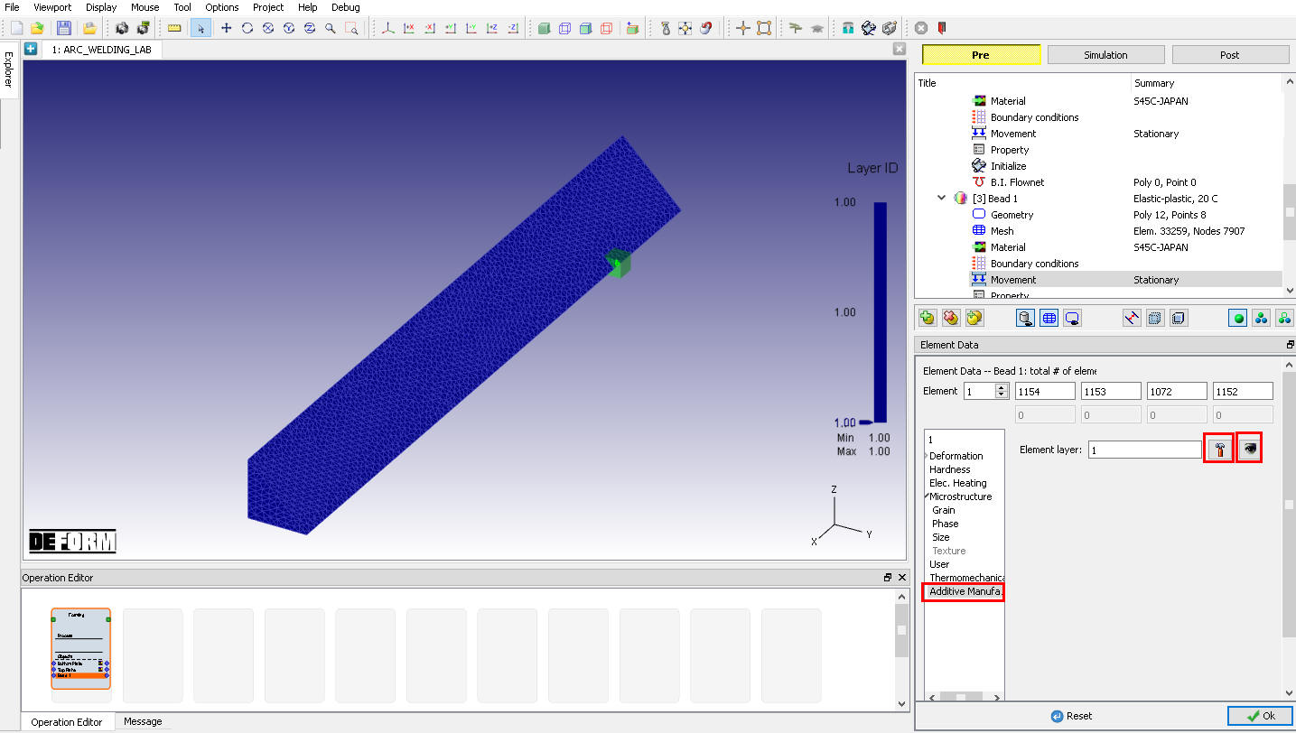
Element Dialog – Initialization of layer ID
Contact
In Contact page, add three relations by clicking on ![]() button, select first relation and then select Bottom plate as Master and Top plate as Slave. Click on
button, select first relation and then select Bottom plate as Master and Top plate as Slave. Click on ![]() , under Thermal tab define Heat Transfer Coefficient as 1000 and click on
, under Thermal tab define Heat Transfer Coefficient as 1000 and click on ![]() . Now select second relation and select Bead 1 as Master and Bottom plate as Slave, click on
. Now select second relation and select Bead 1 as Master and Bottom plate as Slave, click on ![]() , under Thermal tab define Heat Transfer Coefficient as 1000 and click on
, under Thermal tab define Heat Transfer Coefficient as 1000 and click on ![]() . Now select last relation and select Bead 1 as Master and Top plate as Slave, click on
. Now select last relation and select Bead 1 as Master and Top plate as Slave, click on ![]() , under Thermal tab define Heat Transfer Coefficient as 1000 and click on
, under Thermal tab define Heat Transfer Coefficient as 1000 and click on ![]() . Turn on Sticking condition check box in all relations, click the
. Turn on Sticking condition check box in all relations, click the ![]() to determine an intelligent contact tolerance. Click
to determine an intelligent contact tolerance. Click ![]() to generate contact and click “ Yes “ in Sticking condition pop-up, generated contact is as shown in the Fig. AWL1.28. Click
to generate contact and click “ Yes “ in Sticking condition pop-up, generated contact is as shown in the Fig. AWL1.28. Click ![]() to Stopping controls page.
to Stopping controls page.
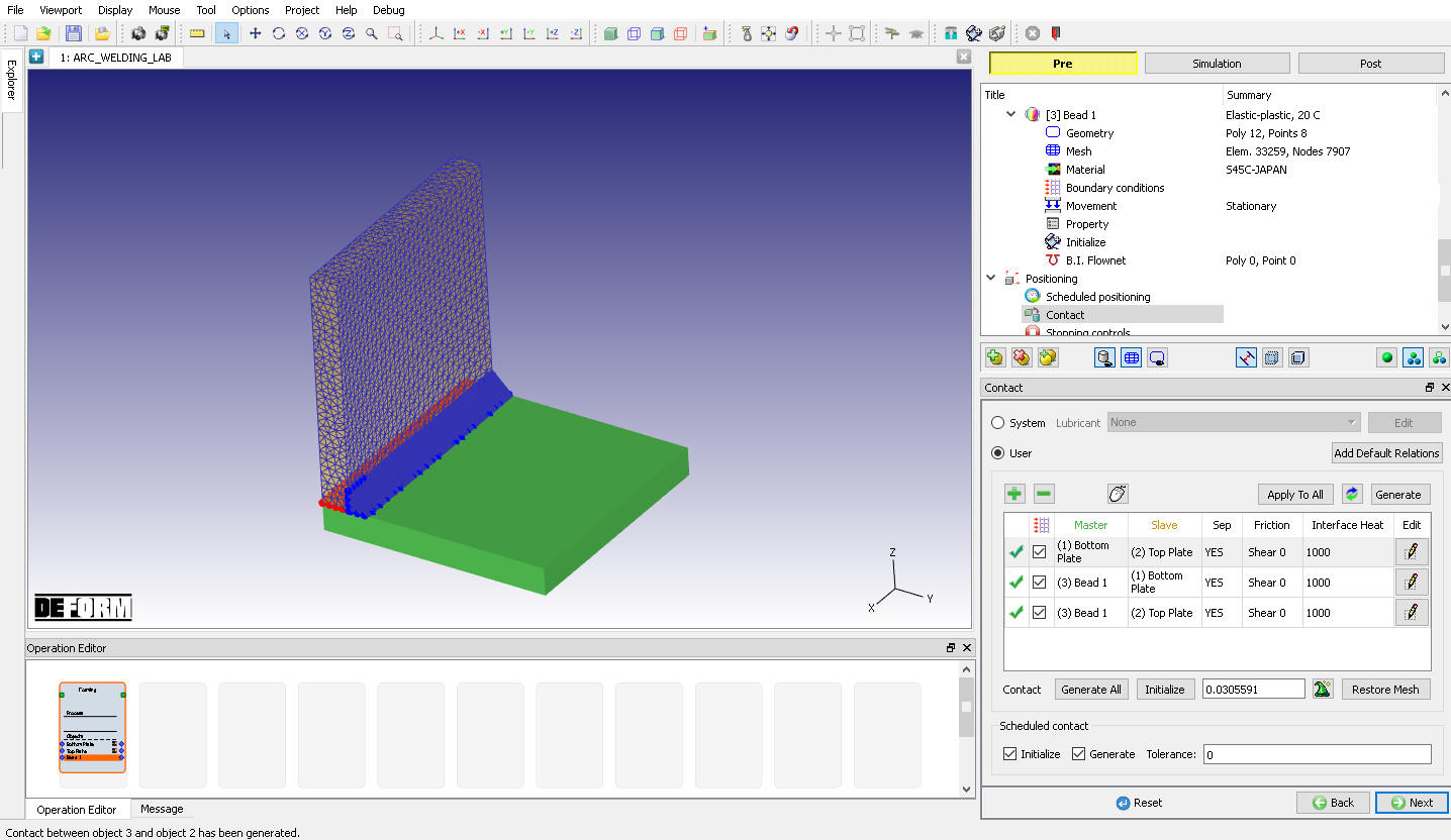
Contact page
Stopping Controls
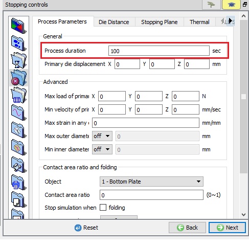
Switch to Expert mode by clicking on ![]() button, define the Process Duration as 100 sec as shown in Fig. AWL1.29. Click
button, define the Process Duration as 100 sec as shown in Fig. AWL1.29. Click ![]() to Step page.
to Step page.
Stopping Controls (Expert mode)
Step Controls
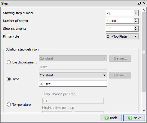
Switch to Guided mode by clicking on ![]() , define the Number of Step s as 10000 , Step increment as 10 and Timeper step as 0.1 sec as shown in Fig. AWL1.30.
, define the Number of Step s as 10000 , Step increment as 10 and Timeper step as 0.1 sec as shown in Fig. AWL1.30.
Step - Guided mode
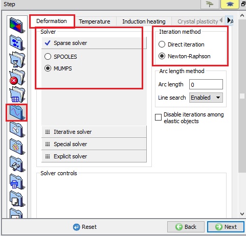
Switch to Expert mode by clicking on ![]() button, under
button, under ![]() Solver settings click on Deformation tab, select MUMPS solver and Iterationmethod as Newton-Raphson as shown in Fig. AWL1.31.
Solver settings click on Deformation tab, select MUMPS solver and Iterationmethod as Newton-Raphson as shown in Fig. AWL1.31.
Solver Settings -Deformation tab
Under Solver settings - Thermal tab select MUMPS solver as shown in Fig. AWL1.32.

Solver Settings -Thermal tab
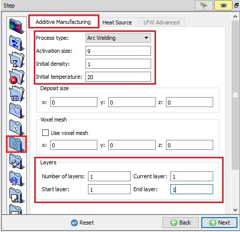
Select AdvancedProcess Condition![]() , under Additive Manufacturing tab, enter the following data:
, under Additive Manufacturing tab, enter the following data:
Select Process type as “Arc Welding “,
Activation size as 9 (for more information refer Activation size in Additive Manufacturing Lab),
Initial density as 1 ,
Initial temperature as 20 ,
Define Number of layers as1 , Current layer as 1 , Startlayer as 1 and Endlayer as 1 as shown in the Fig. AWL1.33.
Process Condition - Additive Manufacturing
Under Heat Source tab, click on ![]() button to add Heat source. Select Double Ellipsoid and define value of Qf as 1000, Qr as 1000, Cf as 0.04, Cr as 0.01, Cy as 0.04 and Cz as 0.01 as shown in Fig. AWL1.34.
button to add Heat source. Select Double Ellipsoid and define value of Qf as 1000, Qr as 1000, Cf as 0.04, Cr as 0.01, Cy as 0.04 and Cz as 0.01 as shown in Fig. AWL1.34.
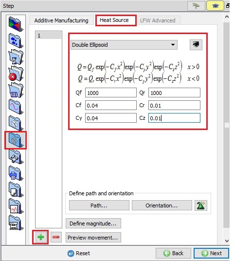
Process Condition - Heat Source page
In this lab we will define the Path and Orientation data using Auto Extract option. Click on ![]() to Extract path and Orientation from geometry automatically, select weld bead as “ Bead 1” under object list as shown in Fig. AWL1.35.
to Extract path and Orientation from geometry automatically, select weld bead as “ Bead 1” under object list as shown in Fig. AWL1.35.
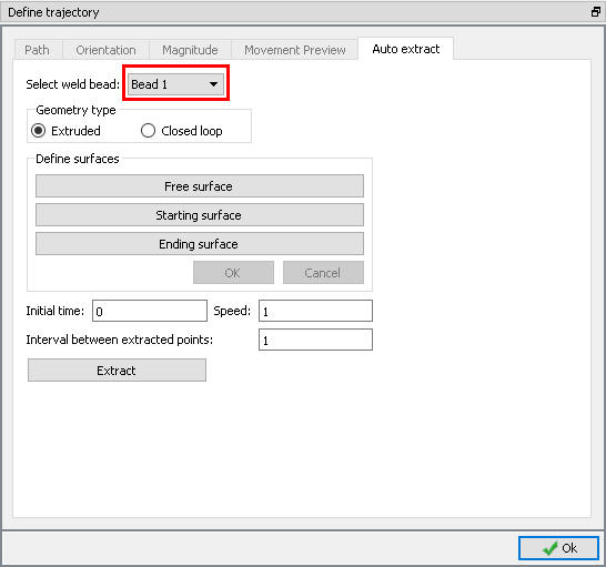
Weld bead object selection
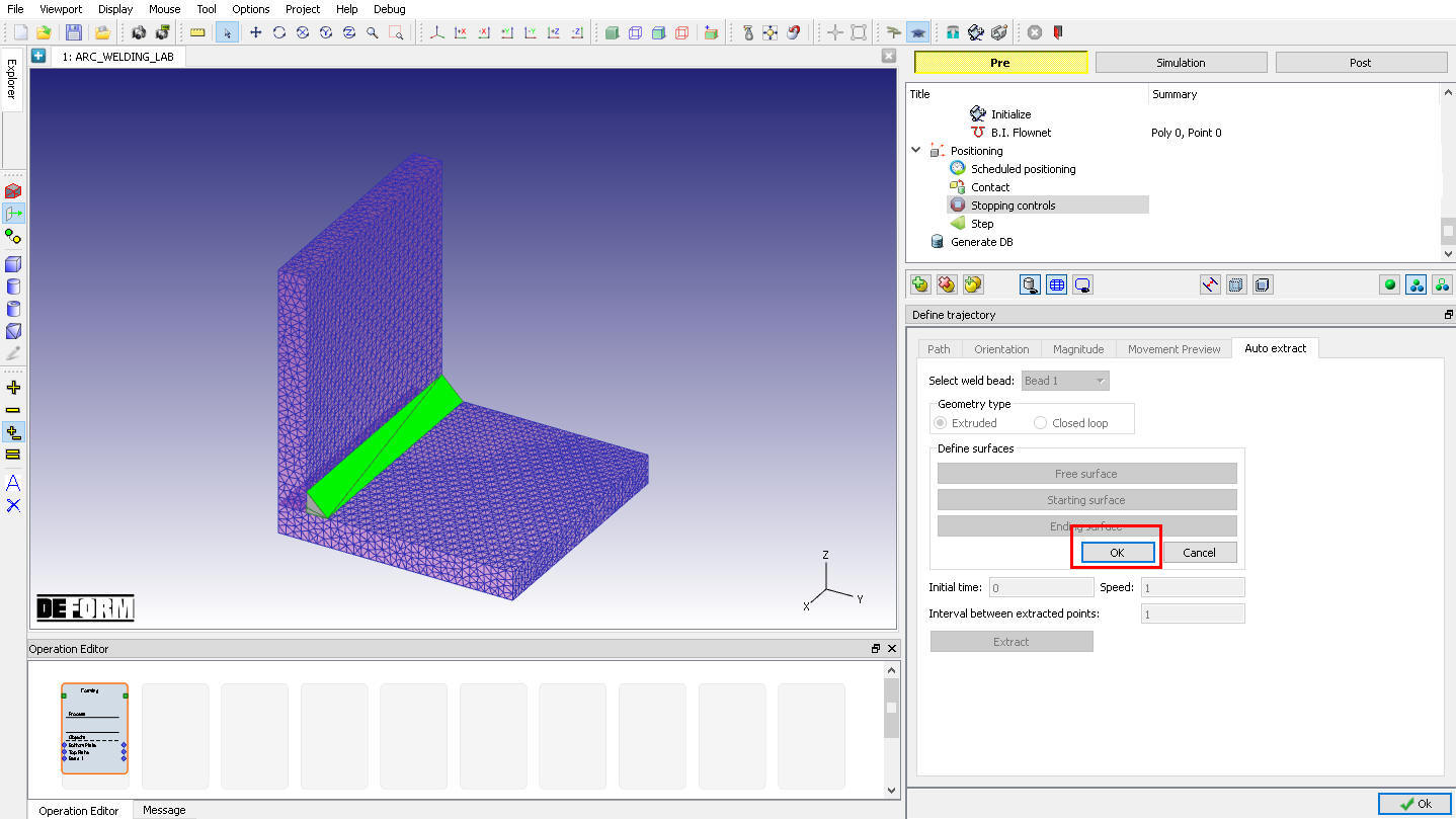
Since the bead geometry is Extruded type select Geometry type as Extruded radio button, then click ![]() button and select inclined surface as Free surface as shown in Fig. AWL1.36. Click
button and select inclined surface as Free surface as shown in Fig. AWL1.36. Click ![]() to close the Free surface page.
to close the Free surface page.
Selecting Free surface
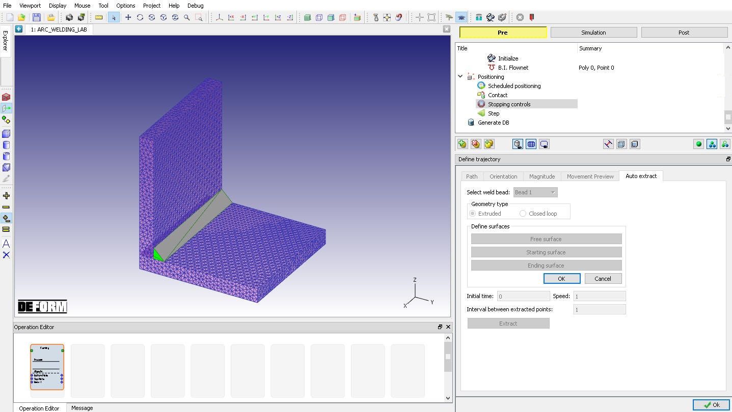
Click on ![]() button and select Starting surface as +X direction surface of Bead 1 as shown in Fig. AWL1.37. and click on
button and select Starting surface as +X direction surface of Bead 1 as shown in Fig. AWL1.37. and click on ![]() button.
button.
Selecting Extruded Starting surface
Similarly, click on ![]() button and select Endingsurface as -X direction surface of Bead 1 and click on
button and select Endingsurface as -X direction surface of Bead 1 and click on ![]() to close. Now to extract Path and Orientation from geometry click on
to close. Now to extract Path and Orientation from geometry click on ![]() button with default settings as shown in Fig. AWL1.38. Click on
button with default settings as shown in Fig. AWL1.38. Click on ![]() to close the Auto Extract page. User can define “Initial time”, “Speed” and “Interval between extracted points” which will be used to define the function data.
to close the Auto Extract page. User can define “Initial time”, “Speed” and “Interval between extracted points” which will be used to define the function data.
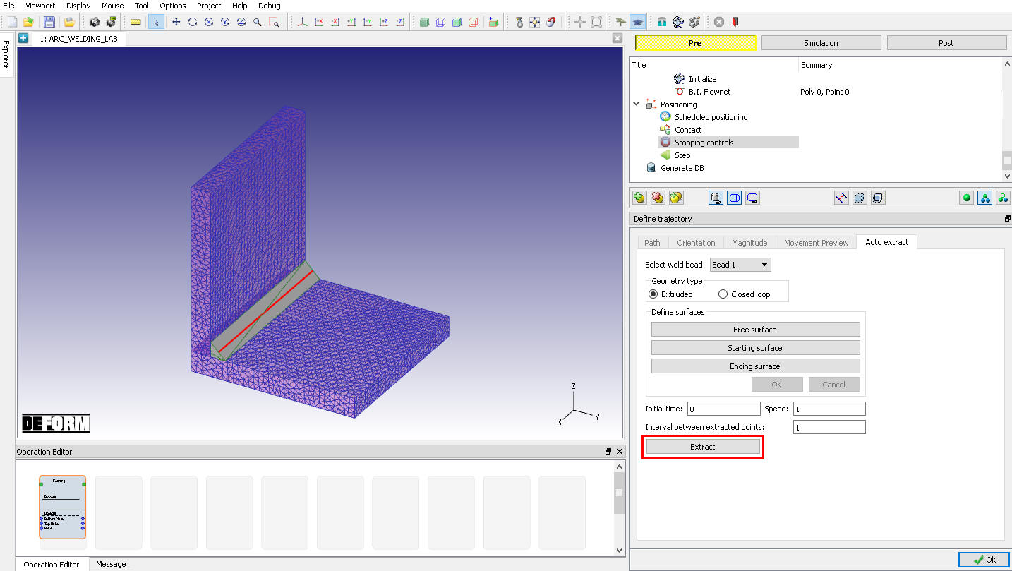
Extracting path and orientation using Extract button
After extracting the path and orientation, click on ![]() and
and ![]() button and observe the extracted path and orientation data. (See Fig. AWL1.39. and Fig. AWL1.40.)
button and observe the extracted path and orientation data. (See Fig. AWL1.39. and Fig. AWL1.40.)
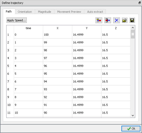
Extracted Path data
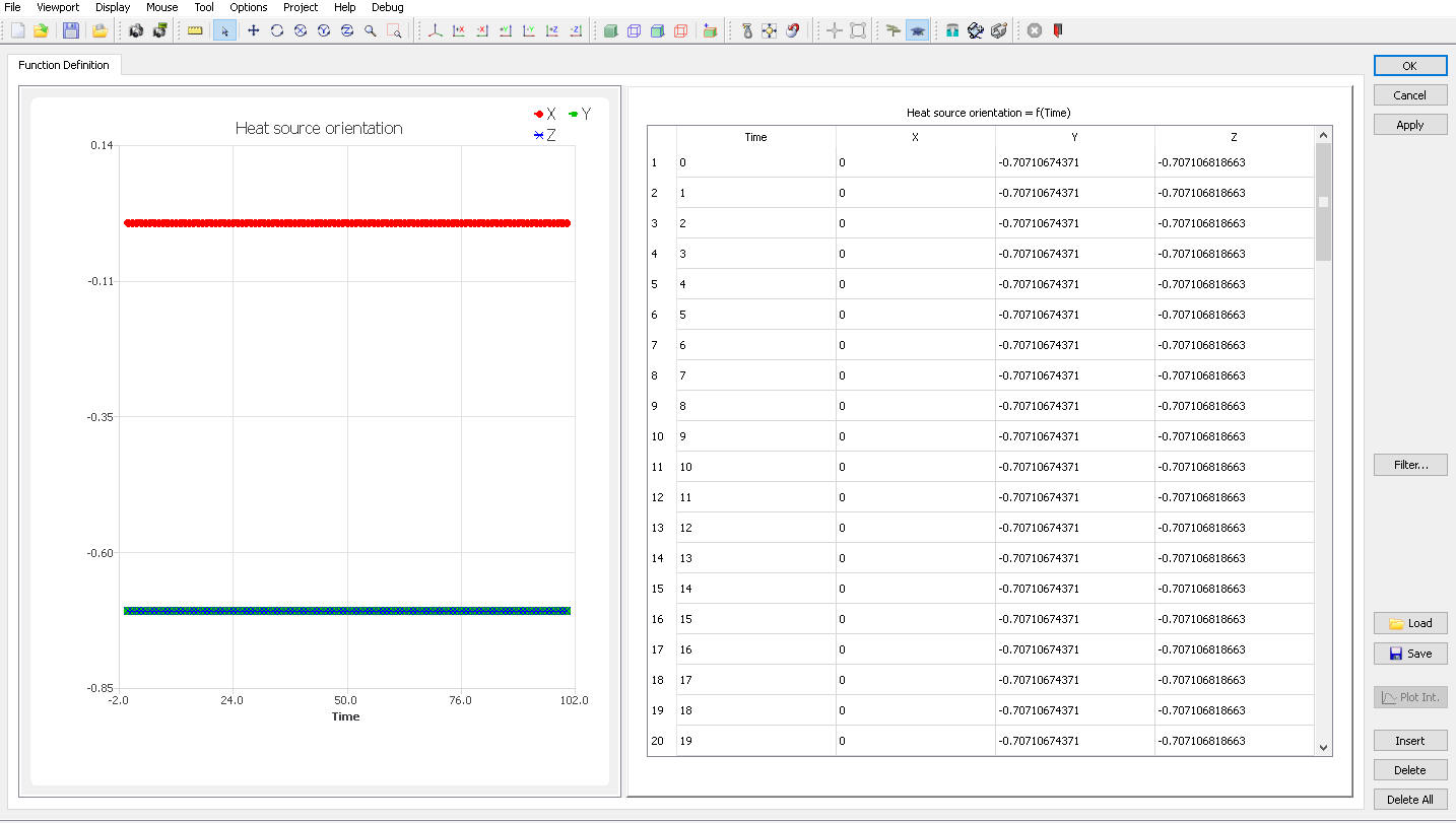
Extracted Orientation data
Click on ![]() button, select Heat source as On/off , add two rows by clicking on
button, select Heat source as On/off , add two rows by clicking on ![]() button and define the Magnitude. In this lab we are defining constant magnitude as shown in Fig. AWL1.41. Click
button and define the Magnitude. In this lab we are defining constant magnitude as shown in Fig. AWL1.41. Click ![]() to close Magnitude window
to close Magnitude window
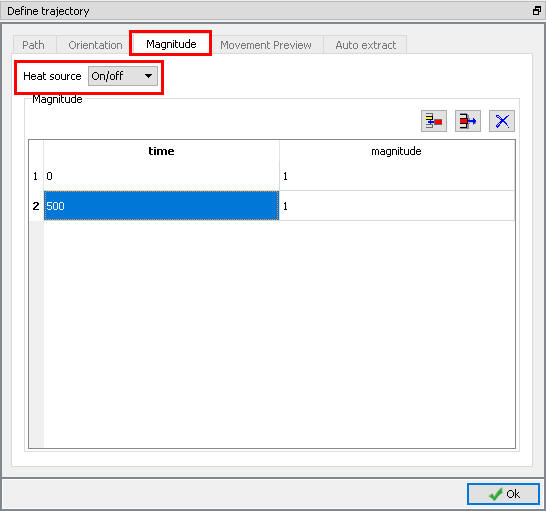
Magnitude window
We can preview the movement by clicking on ![]() button and play the animation. We can vary the movement preview speed and Arrow size using respective sliding bar as shown in Fig. AWL1.42. As the simulation preview progresses user can observe the arrow following the welding path. Click
button and play the animation. We can vary the movement preview speed and Arrow size using respective sliding bar as shown in Fig. AWL1.42. As the simulation preview progresses user can observe the arrow following the welding path. Click ![]() to close Magnitude window and click
to close Magnitude window and click ![]() to Generate DB page.
to Generate DB page.
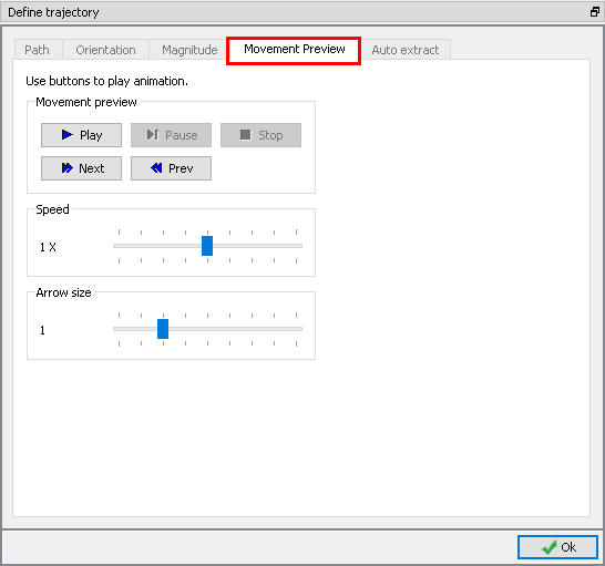
Movement Preview window
Generate DB
In Generate DB page, click ![]() to see if anything was missed in the setup and then click on the
to see if anything was missed in the setup and then click on the ![]() button to generate the database. Observe the message in Message tab informing database generation status.
button to generate the database. Observe the message in Message tab informing database generation status.
Running Simulation
Once the database has been generated, switch to the Simulation mode by clicking on ![]() button above the operation tree. Click on the
button above the operation tree. Click on the ![]() action label to open the Run Options dialog as shown in Fig. AWL1.43. Use the default Continue Run option to select “Continue from the last step ” (from step -1) option and then select the Simulation mode as Interactive and click on
action label to open the Run Options dialog as shown in Fig. AWL1.43. Use the default Continue Run option to select “Continue from the last step ” (from step -1) option and then select the Simulation mode as Interactive and click on ![]() button to run the simulation.
button to run the simulation.
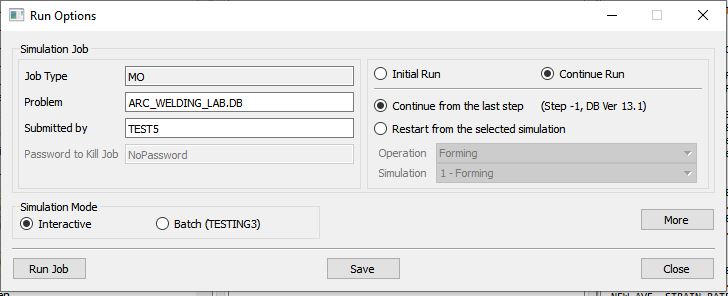
Run Simulation Window
Monitor the progress of the simulation by looking at the Simulation Message and Simulation Log tab, making sure that the ![]() option is checked.
option is checked.
Post Processing
When the simulation is completed, review the results by switching to Post mode using the ![]() button above the Simulation tool bar.
button above the Simulation tool bar.
Play through the steps using animation option and observe the Bead 1 formation (See Fig. AWL1.44. and Fig. AWL1.45.).
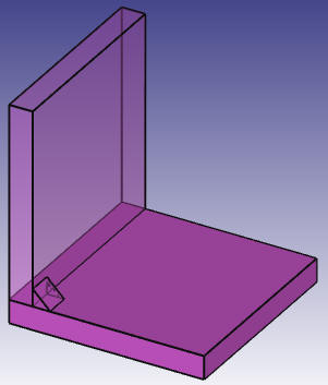
Bead 1 formation at the end of step 50
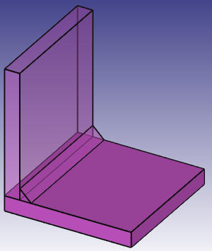
Bead 1 formation at last step
Plot Temperature state variable and observe the temperature distribution (See Fig. AWL1.46.).
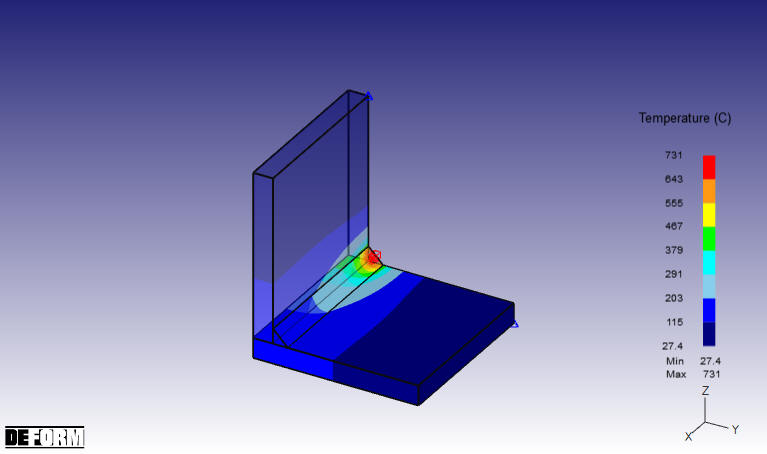
Temperature Distribution at last step