9.2. Defining Step
9.2.1. imulation Steps
-
Starting step number (NSTART)
-
Number of simulation steps (NSTEP)
-
Step increment to save (STPINC)
-
Primary die (PDIE)
9.2.2. Step Increment
-
Step definition (STPDEF)
-
Selecting time step and number of steps
-
Sub-stepping Controls
-
Advanced Step Controls
Simulation Steps 
The DEFORM system solves time dependent non-linear problems by generating a series of FEM solutions at discrete time increments. At each time increment, the velocities, temperatures, and other key variables of each node in the finite element mesh are determined based on boundary conditions, thermo mechanical properties of the work piece materials and possibly solutions at previous steps. Other state variables are derived from these key values, and updated for each time increment. The length of this time step, and number of steps simulated, are determined based on the information specified in the step controls menu as shown in Fig. 9.2.1.

Simulation steps
Starting step number (NSTART)[2D, 3D]
If a new database is written, the specified step number (NSTART) will be the first step in the database. If data is written to an existing database, the pre-processor data will be appended to this database in proper numerical order, and any steps after the one specified will be overwritten.
The negative (-n) flag on the step number indicates that the step was written to the database by the pre-processor (either by manual generation of a database step or by an automatic remesh), not by the simulation engine.
Note:
All pre-processor generated steps should have a negative step number.
Number of simulation steps (NSTEP) [2D, 3D]
The number of simulation steps parameter defines the number of steps to run from the starting step number. The simulation will stop after this number of simulation steps have run, unless stopping control is triggered to stop the simulation or if the simulation runs into a problem. For example, if the starting step number is -35 (NSTART), and 30 steps (NSTEP) are specified, the simulation will stop after the 65th step, unless another stopping control is triggered first.
Step increment to save (STPINC) [2D, 3D]
The step increment (STPINC) to save in the database controls the number of steps that the system will save in the database. When a simulation runs, every step must be computed, but does not necessarily need to be saved in the database. Storing more steps will preserve more information about the process, consequently it will require more storage space.
Primary die (PDIE) [2D, 3D]
The primary die (PDIE) is the object for which many stopping and stepping criteria are defined. For example, stopping distance based on primary die stroke. When the stroke of the object defined as the primary die reaches the value for primary die displacement, the simulation will be stopped whether or not more steps were specified. The Step By Stroke feature determines step size based on the movement of the primary die.
The primary die is usually assigned to the object most closely controlled by the forging machinery. For example, the die attached to the ram of a mechanical press would be designated as the primary object.
Secondary step controls (STPINC) [2D,3D]
The secondary step controls option allows the step saving increment to be changed for a portion of the simulation. This option is useful when users want to save either more or less steps for a portion of simulation. Once the selected stopping controls value reaches the defined Secondary step controls value, then the Secondary step increment value will be considered to save the steps to the database.
We can use this option with “Time”, “Primary die displacement”, “Primary die load”, “Contact area ratio” and “Min die distance” stopping controls.
When we click on ![]() button, it will estimate the final 10 % of the process as the selected stopping criterion.
button, it will estimate the final 10 % of the process as the selected stopping criterion. ![]() button will be active only when the respective stopping controls data is defined.
button will be active only when the respective stopping controls data is defined.
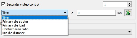
Secondary step controls option
Step Increment 
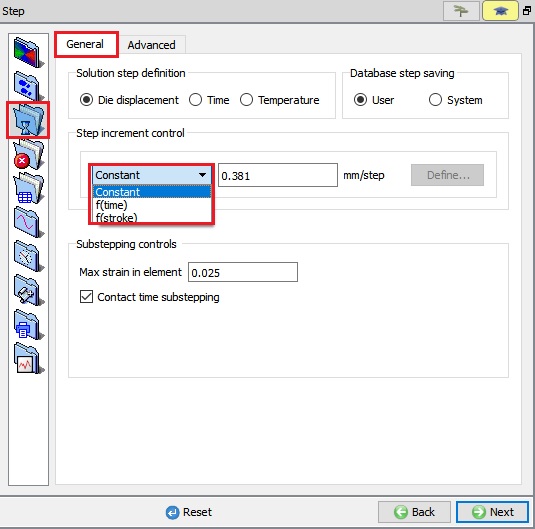
For Step increment settings options see Fig. 9.2.3.
(a)

(b)
Step Controls; (a) For 2D (b) For 3D
Step increment control (DSMAX/DTMAX) [2D, 3D]
User can define (the maximum allowable) time step size as a function of “stroke” (DSMAX) or “time” (DTMAX).
Solution step size can be controlled by time step or by displacement of the primary die. If stroke per step is specified, the primary die will move the specified amount in each time step. The total movement of the primary die will be the displacement per step multiplied by the total number of steps. If time per step is specified, the time interval per step will be used. The die displacement per step will be the time step times the die velocity.
From 3DV61, the definition of step increment control has been enhanced to include both the time and stroke dependent step functions. This means, step size (both time per step and stroke per step) can now be defined as a function of time or stroke. This functionality enables finer resolution of saved model information, where it is desired. (typically towards the end of the stroke, where steep changes of die load and cavity filling or flash formation can take place).
Stroke per step is frequently more intuitive. However, time per step must be specified for any problem in which there is no die movement (such as heat transfer) or for any problem where force control is used.
Step definition (STPDEF) [2D, 3D]
There are three modes (STPDEF) for defining steps,
- User In user defined steps mode, the steps correspond to the NSTEP value. This is the default which does not have to be changed in almost all cases.
- System In the system defined steps mode each sub step is saved to the database and is treated as a step. This option is primarily used for debugging purposes.
- Temperature In temperature based sub stepping, the DTPMAX settings control the time stepping. The purpose for these controls is to specify the time stepping of a simulation that is driven by thermal-induced deformation.
Selecting time step and number of steps [2D, 3D]
Proper time step selection is important. Too large a time step can cause inaccuracy in the solution, rapid mesh distortion or convergence problems. Too small a time step can lead to unnecessarily long solution times. The following section provides some guidelines for selecting time steps. The maximum displacement for any node should not exceed about 1/3 the length of its element edge length in one step. For flow around a tight corner, flash forming, or similar highly localized deformations, time steps may need to be defined to give a node movement of as small as 1/10 or the element edge length. Thus, for a finer mesh, smaller steps are required than for a coarser mesh. This prevents the mesh from becoming overly distorted in a single time step.
The time step can be determined by the following method:
- Using the measurement tool, measure one of the smaller elements in the deforming object (this must be done after a mesh has been generated)
- Estimate the maximum velocity of any region of the workpiece (for most problems, this will be the die velocity. For extrusion problems it will be the die velocity times the extrusion ratio) If some steps have already been run, display object velocity clcik on
 (Node data) (use the
  icon to display a velocity vector plot and maximum and minimum values).
 - Divide the result of 1 by the result of 2, and take about 1/3 of this value as the time step. This is a rough estimate, so extreme accuracy is not critical.
- The number of steps is given by,
Refer also to the Polygon Length Sub-Step feature under Advanced Step Controls If there is insufficient information available to calculate the total number of steps, three alternatives are available:
- A general guideline of 1% to 3% height reduction per step can be used.
- Specify an arbitrarily large number of steps, and use an alternative stopping control, such as time or total die stroke.
- Make a good estimate of the number of steps required for the given step size, then specify about 120% of this value. Allow the simulation to overshoot the target, then use a step near, but not at the end as a final solution.
Sub-stepping Controls
- Strain per step (DEMAX) [2D, 3D]:
The maximum element strain increment limits the amount of strain that can accumulate in any individual element during one time step. If a non-zero value is assigned to DEMAX, a new sub step will be initiated when the strain increment in any element reaches the value of DEMAX.
- Contact Time (DTSUB) [2D, 3D]
After either DSMAX or DTMAX is prescribed, the deformation simulation may be broken into smaller sub steps, depending on the assigned value of DTSUB.
[2D] : For a default DTSUB= 0.0, the system will enable contact sub-stepping.
For DTSUB= 1.0, no sub-stepping will be done.
[3D] : Contact time controls whether or not sub stepping is performed when nodes contact a master surface. By default (DTSUB= 1), if a node contacts a master surface a fraction of the way through a time step, the time step is subdivided, and that step is run again at the fraction of the time increment. This will place the node on the surface at the end of the time step. For 3D problems with a large number of nodes contacting master surfaces, this can cause huge increases in execution time.
If DTSUBis set to 1, contact time sub stepping is disabled. Nodes will be allowed to penetrate the master surface, but then will be artificially moved back to surface at the end of the time step. This will allow significantly faster execution time. However, if the defined time step is too large, some volume loss and mesh distortion may occur.
In general, it is recommended that DTSUBbe set to 1 and that the time step guidelines described above be followed carefully. Use of polygon length sub stepping, DPLEN, will also control volume loss and mesh distortion, without severe execution time increase.
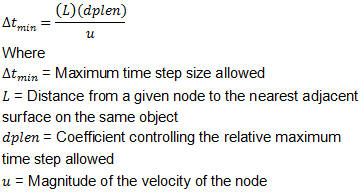
- Polygon length sub step (DPLEN) [3D]
Polygon length sub stepping (DPLEN)places an upper limit on the absolute distance a surface node can move in a given time step.
 |
|
—|—
Legal values of DPLEN are from 0 to 1. A value of 0 will disable sub stepping. Recommended values are 0.2 to 0.5, with 0.2 being more conservative, and hence slower, and 0.49 being more aggressive, and faster, but less accurate. Values larger than 0.5 can be used, but may allow unacceptable mesh degeneration.
- Adaptive contact penetration control check box
This option implicit contact controls for EP and plastic models. From v12.0 instead of placing DEF_CNT.DAT file inside working directory in GUI option has been implemented.
Advanced Step Controls
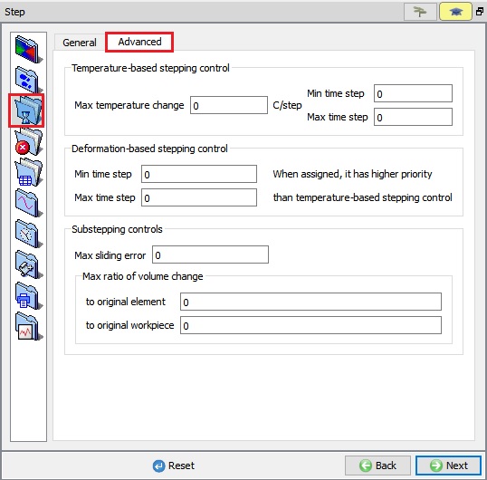
This menu gives more options for special simulations where precision control of time step size is required (See Fig. 9.2.4.).
(a)
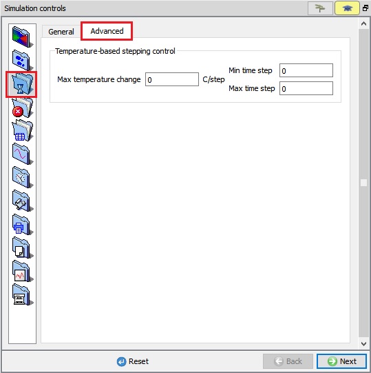
(b)
Advanced stepping menu; (a) For 2D (b) For 3D
-
Temperature change per step (DTPMAX) [2D, 3D]: The maximum temperature change increment limits the amount that the temperature of any node can change during one time step. If a non-zero value is assigned, a new sub step will be initiated when the temperature change at any node reaches the value of DTPMAX. The maximum/minimum time step are the largest and smallest time step allowable with the temperature based sub-stepping.
-
Deformation time per step (DTPMAX) [2D]: If a non-zero value is assigned to Min. time step and Max. time step in Deformation-based stepping control group box, a new step size will be determined at each step, depending on the solution convergence rate. When the solution convergence rate is good, the time step size will be increased. But, when the solution convergence rate is poor, the time step size will be reduced. The minimum/maximum time steps are the largest and smallest time step allowable when determining the time step size. When this step control is defined, it has higher priority than Temperature change per step control.
-
Maximum Sliding Error [2D] : This stepping control is not generally recommended. Please contact SFTC at support@deform.com for more information.
-
Volume change per step (DVMAX) [2D] : During a deformation time step, elements typically experience a change in volume (DVMAX). Over time, this volume change generally results in volume loss. The volume loss generally increases with increasing step sizes and increasing total height reduction
 where
where  refers to a height reduction per step and
  refers to the height of an object. For problems where volume loss is significant, the volume loss also can be controlled by specifying the maximum amount of volume change that an individual element or an object can experience during a time step. If a non-zero value is assigned, a new sub step will be initiated when the ratio of the volume change to the original volume of any element exceeds the specified value.
Related Topics:
9.1. Simulation type Settings
9.3. Stopping Controls
9.4. Remesh Criteria
9.5. Solver Settings
9.6. Process Conditions
9.7. Advanced Options
9.8. Control Files
9.9. Thermomechanical variables