42.1. Ring Rolling Operation
42.1.1. How to add the Ring Rolling Operation
42.1.2. Process Selection
42.1.3. Simulation setup
42.1.4. Material List
42.1.5. Object page
- Objects for Symmetry model type setup
42.1.6. Defining Workpiece – Ring Object
-
Extract cross-section from imported 3D Geometry
-
Extract cross-section from imported 3D Mesh
42.1.7. Defining 2D Cross-section
42.1.8. Generating 2D mesh
42.1.9. Generating 3D Geometry
-
Revolve Settings
-
Importing 3D Geometry
42.1.10. Generating 3D Mesh
42.1.11. Orientation
42.1.12. Material Page
42.1.13. Workpiece BCC
41.1.14. Property
42.1.15. Initialize
42.1.16. Defining Driving Roll
-
Defining Driving Roll Orientation
-
Defining Driving Roll Movement
42.1.17. Defining Pressure Roll
-
Pressure Roll Orientation
-
Defining Pressure Roll Movement
42.1.18. Defining Axial Roll
-
Axial Roll Orientation
-
Axial Roll Movement Page
42.1.19. Axial Roll #2 Page
42.1.20. Positioning
42.1.21. Scheduled positioning
42.1.22. Contact
42.1.23. Stopping Controls for Ring Rolling Simulation
42.1.24. Step and remeshing controls for Ring Rolling
42.1.25. Simulation controls
-
Stability Control
-
Advanced Control
42.1.26. Generate DB
42.1.27. Setting up Ring Rolling Operation in Batch mode
-
Workpiece–Ring is Read from DB
-
Extract Cross-section for Read from DB object
-
Generating the Workpiece 2D Cross-section mesh
-
Generating Workpiece 3D Mesh
42.1.28. Running Simulation
How to add the Ring Rolling Operation
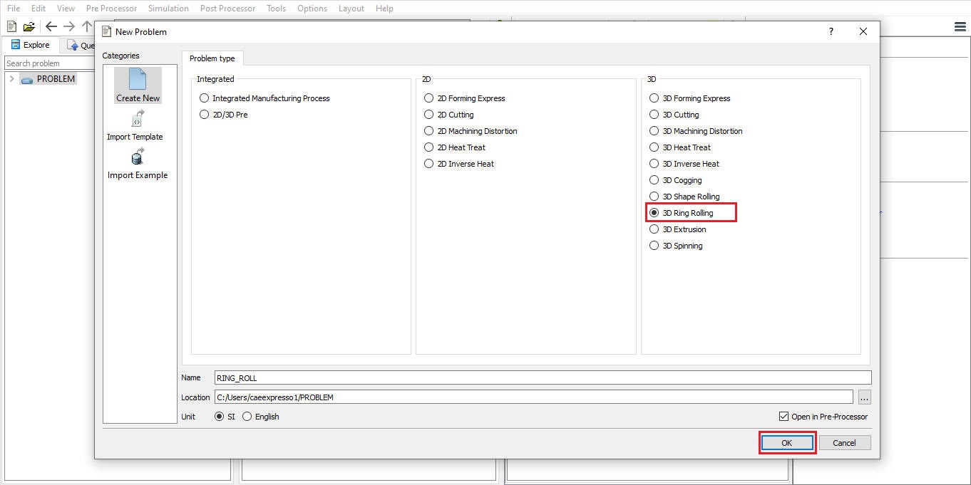
Ring Rolling operation can be setup in Integrated Manufacturing Process environment that can be accessed from GUI Main. Create a new problem by either selecting File ![]() New Problem or by clicking the New Problem
New Problem or by clicking the New Problem ![]() icon. Select 3D Ring Rolling radio button under problem type and unit system. Click on
icon. Select 3D Ring Rolling radio button under problem type and unit system. Click on ![]() button (see Fig. 42.1.1.). Integrated Manufacturing Process wizard will open, we can see that 3D Ring Rolling operation is added in Operation editor.
button (see Fig. 42.1.1.). Integrated Manufacturing Process wizard will open, we can see that 3D Ring Rolling operation is added in Operation editor.
Adding Ring Rolling Operation from GUI Main
We can also add Ring rolling operation into Integrated Manufacturing Process environment from the New Project pop-up when a new problem is opened in Integrated Manufacturing Process environment as shown in Fig. 42.1.2. Using “Copy Existing project” option, we can import previous saved projects as new project from the New Project pop-up.
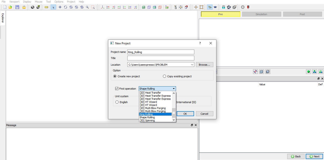
Assign Project name and First Operation selection in New Project window
We can also add Ring Rolling operation to operation editor from explorer tab in Integrated Manufacturing Process environment, by clicking on ![]() button next to Ring Rolling operation (see Fig. 42.1.3.) or by drag and drop Ring Rolling operation into operation editor window.
button next to Ring Rolling operation (see Fig. 42.1.3.) or by drag and drop Ring Rolling operation into operation editor window.
As the Ring Rolling operation is added into operation editor process selection page will be opened in property settings modification window.
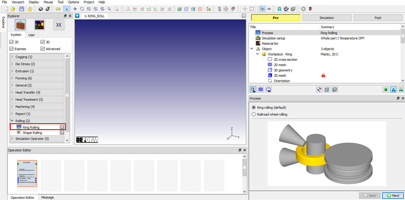
Adding operation from Explorer Operation list
Ring Rolling operation can also be added in batch mode as a part of multiple operation setup, for more details on this type of setup refer 42.1.27. Setting up Ring Rolling Operation in Batch mode.
Process Selection
In Process page user will be selecting the type of Rolling simulation to be performed (see Fig. 42.1.4.) by default the Ring Rolling process is select. If the user is interested in the Railroad wheel rolling process than we can select the respective process option as shown in the Fig. 42.1.5.
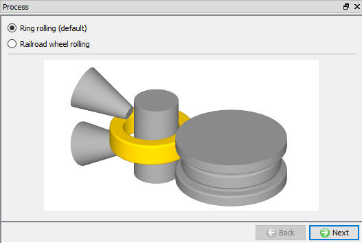
Process Page (Ring Rolling)
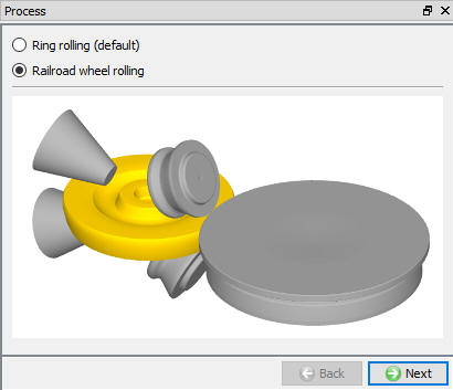
Process Page (Railroad Wheel Rolling)
Simulation setup
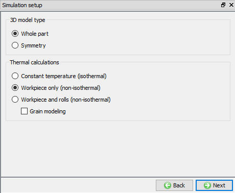
In Simulation setup page user will be specifying the process settings to be used for problem setup.
3D model type: In 3D model type we have options to select Whole part or symmetry depending on the geometry symmetry to be modelled in the setup.
Thermal calculations: In thermal calculations tab (see Fig. 42.1.6.) options are available to select the object types on which thermal calculations need to be performed.
-
Constant temperature (isothermal) : When user selects this option then simulation does not perform any thermal calculations. User can use this option when temperature change in process is negligible.
-
Workpiece only (non-isothermal): When user selects this option then simulation does thermal calculation only on workpiece, this option is useful in most of the cases where user is interested in temperature change of the workpiece only.
-
Workpiece and rolls (non-isothermal): This option can be used when thermal calculations need to be done for both workpiece and rolls to observe change in temperature of these objects.
Grain modeling: If user is interested in Grain size output, he can select the Grain modeling check box which activates grain size calculation. Grain modeling is available only for non-isothermal process.
Simulation setup Page
Material List
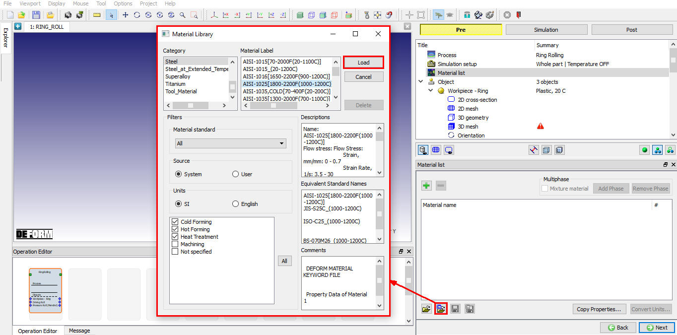
Material page is used to create a new material or load material from database and if necessary, modify its properties by selecting respective material from the operation tree. From Material List page, user can load the material using Import Material data from a File ![]() or Using Load form Library option
or Using Load form Library option ![]() (see Fig. 42.1.7.). User can also save the material using
(see Fig. 42.1.7.). User can also save the material using ![]() and
and ![]() .
.
Material list Page
Object page
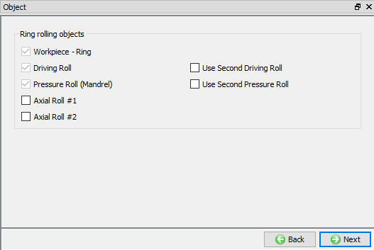
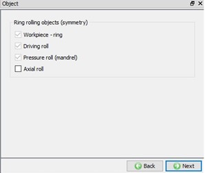
Object page lists the objects that can be used based on the process type selected in the “Process” page. Objects available for Ring Rolling process (see Fig. 42.1.8.) are,
-
Workpiece – Ring,
-
Driving Roll
-
Pressure Roll (Mandrel)
-
2 Axial rolls
By default, workpiece – Ring, Driving Roll and Pressure Roll (Mandrel) are selected and are mandatory for setting up the Ring Rolling Process. If user requires additional objects then respective check boxes can be checked for Axial rolls, Secondary driving roll and Secondary pressure roll.
Object Page (Ring Rolling)
Objects for Symmetry model type setup
For symmetry model we will be modelling only one half of the setup hence the object list is as shown in the Fig. 42.1.9.
Objects page for symmetry model
Defining Workpiece – Ring Object
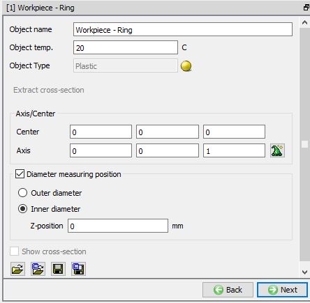
We can define the object name, temperature and Axis/Center of a workpiece in this page as shown in the Fig. 42.1.10. User can import objects from other databases or key files using ![]() ,
, ![]() options or save the object data using
options or save the object data using ![]() ,
, ![]() options.
options.
In case user is importing the 3D object from a file then ![]() will be enabled so that user can extract cross-section of the imported object (See Fig. 42.1.11.) and generate 3D Ring with extracted cross-section.
will be enabled so that user can extract cross-section of the imported object (See Fig. 42.1.11.) and generate 3D Ring with extracted cross-section. ![]() is also active when 3D Geometry of the Ring is imported. Axis/Center for the imported object can be calculated using the
is also active when 3D Geometry of the Ring is imported. Axis/Center for the imported object can be calculated using the ![]() button.
button.
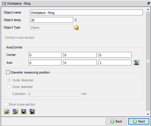
Workpiece-Ring Page
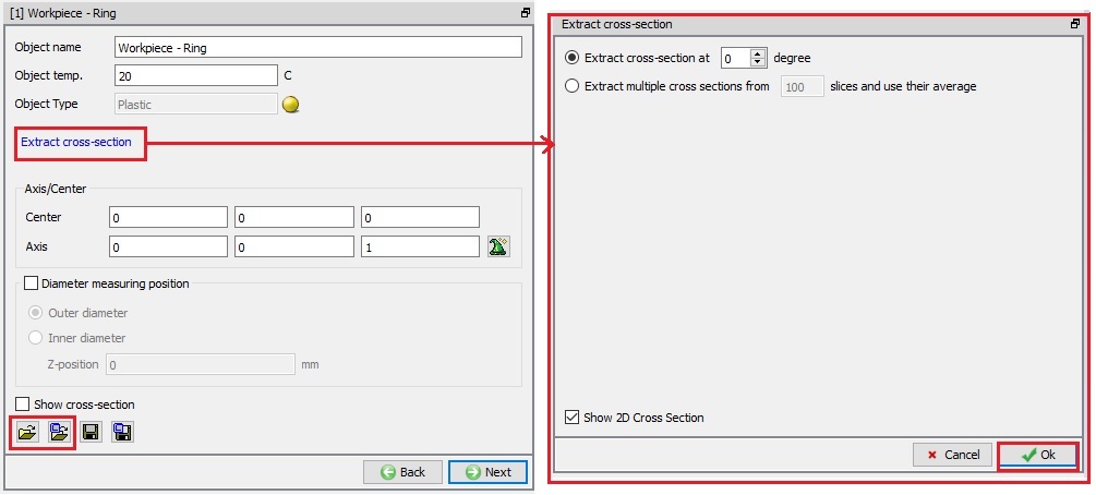
Extracting cross-section from the 3D Shape
Extract cross-section from imported 3D Geometry
-
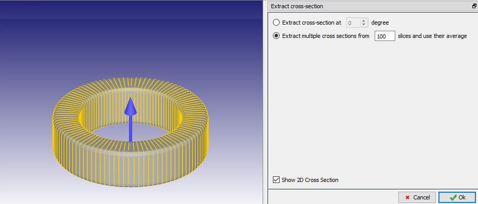
Extract cross-section at degree: This option is used when user wants to extract the cross-section from imported geometry at specified angle User can enter the angle value and the cross-section at that angle is highlighted on the Ring in the display area, see Fig. 42.1.12.
-
Extract Cross-section from slices and use their average: This option is selected for a non-uniform ring when user would like to divide the imported geometry object into specified number of slices and extract cross-section from each slice and use average size as cross-section to generate 3D workpiece. Slices and cross-sections are displayed in display area, see Fig. 42.1.13.
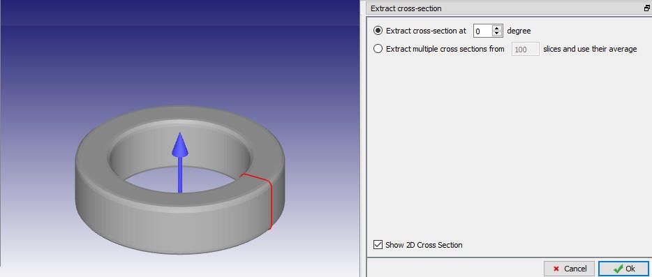
Extracting cross-section at degree
Extracting multiple cross-section from slices and use their average
###
Extract cross-section from imported 3D Mesh
-
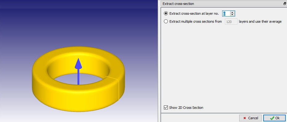
Extract cross-section at layer no. : This option is used when user wants to extract the cross-section from specified layer. User can enter the layer number and the respective layer is highlighted on the ring in the display area, see Fig. 42.1.14.
-
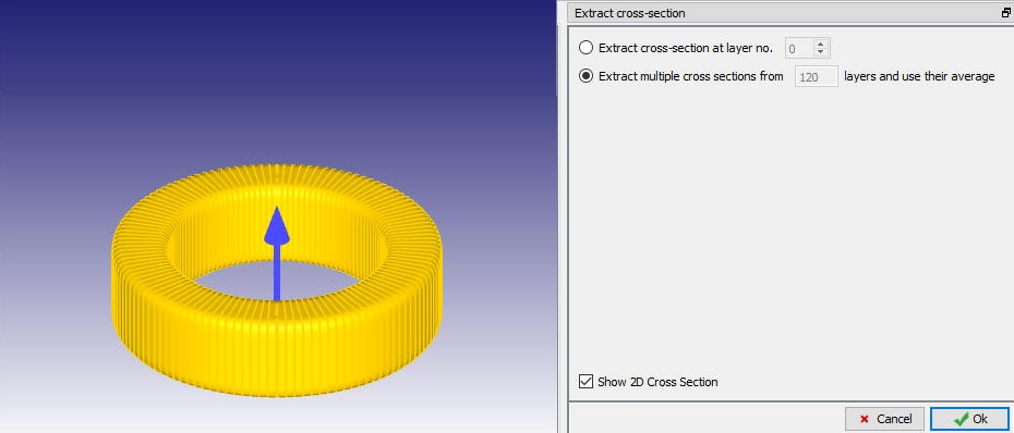
Extract Cross-section from Layers and use their average : This option is selected for a non-uniform ring when user would like to extract multiple cross-sections from all layers and use average size as cross-section to generate ring, number of layers available in the imported object is displayed in display area, see Fig. 42.1.15.
Extracting cross-section at layer no.
Extracting multiple cross-section from layers and use their average
-
Diameter measuring position:
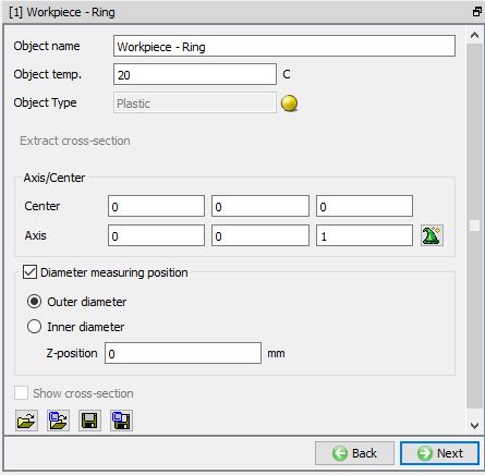
- Outer diameter : This option is used when user wants to stop the Ring Rolling simulation when the outer diameter of the Ring reaches the specified outer value at selected location as shown in Fig. 42.1.16.
Measured outer diameter of workpiece
- Inner diameter : This option is used when user wants to stop the Ring Rolling simulation when the inner diameter of the Ring reaches the specified outer value at selected location as shown in Fig. 42.1.17.
Measured inner diameter of workpiece
- Z position : Using this field, user can define the diameter measurement start position along the Z-axis of the Workpiece - Ring height as show in Fig. 42.1.18.
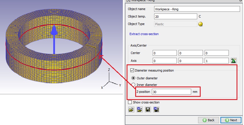
Z-position Diameter measuring position
Note: if we won’t turn on the Diameter measuring position checkbox, then the diameter definition is Max outer diameter. If we turn on the diameter measuring position checkbox, then the selected diameter is used for Stopping controls as Measured outer diameter of workpiece/Measured inner diameter of workpiece.
Defining 2D Cross-section
The user can create the geometry using the ![]() and
and ![]() options as shown in the Fig. 42.1.19. The user can also import the 2D geometry using the
options as shown in the Fig. 42.1.19. The user can also import the 2D geometry using the ![]() ,
, ![]() option and save the 2D geometry using the
option and save the 2D geometry using the ![]() ,
, ![]() options. For more explanation on different options refer 12.1. 2D Geometry Data Defining and 12.2. 2D Geometry Data Editing.
options. For more explanation on different options refer 12.1. 2D Geometry Data Defining and 12.2. 2D Geometry Data Editing.
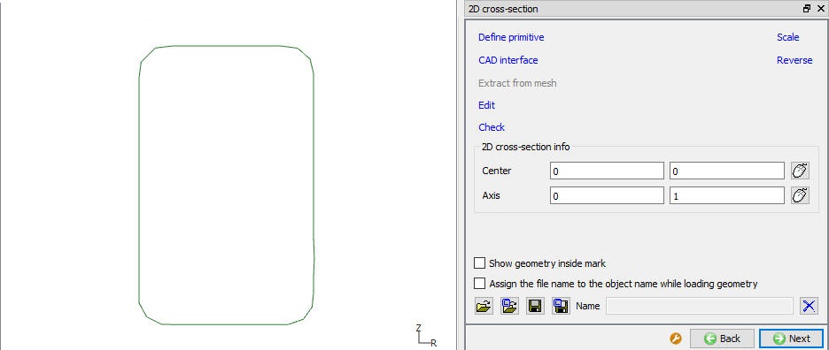
2D Cross Section Page
Generating 2D mesh
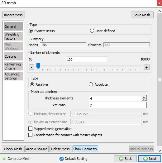
We can generate the 2D Cross Section mesh by defining the number of elements in guided mode as shown in Fig. 42.1.20. Advanced options to control 2D mesh generation can be accessed using expert mode toggle button from tool bar, see Fig. 42.1.22. For more information on advanced options please refer 13.1. 2D Mesh Generation.
Use coarse internal mesh : In Guided Mode user is having this check box to generate coarse internal mesh as shown in Fig. 42.1.21.
Ratio to largest element : User can control the element size relatively using this setting
Generate Mesh ![]() : Once user defines the mesh settings user can generate 2D Mesh using this button.
: Once user defines the mesh settings user can generate 2D Mesh using this button.
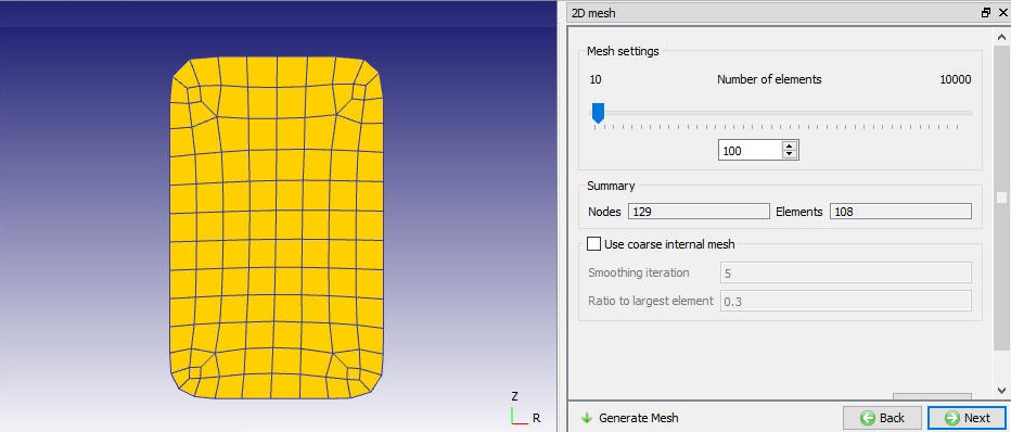
2D Mesh Page (Guided Mode)

2D Mesh generation using coarse internal mesh (Guided Mode)
2D Mesh Page (Expert Mode)
Generating 3D Geometry
User can convert the defined 2D cross section to 3D Geometry by using ![]() option (See Fig. 42.1.23.), settings for converting 2D into 3D by revolving can be defined in Revolve from 2D page as shown in Fig. 42.1.23. and Click
option (See Fig. 42.1.23.), settings for converting 2D into 3D by revolving can be defined in Revolve from 2D page as shown in Fig. 42.1.23. and Click ![]() to convert. For more information on other options please refer 12.3. 3D Geometry data modelling.
to convert. For more information on other options please refer 12.3. 3D Geometry data modelling.
Revolve Settings
Digitization : “Length tolerance fraction”/ “Maximum allowable angle”/ “Minimum allowable angle” can be used to control digitization points on the 2D cross-section.
Number of Layers in hoop direction : User can define number of layers along the rotation of the 2D cross-section.
Center and Axis : Center of the Ring object and axis to be used for revolving the 2D cross-section can be defined here.
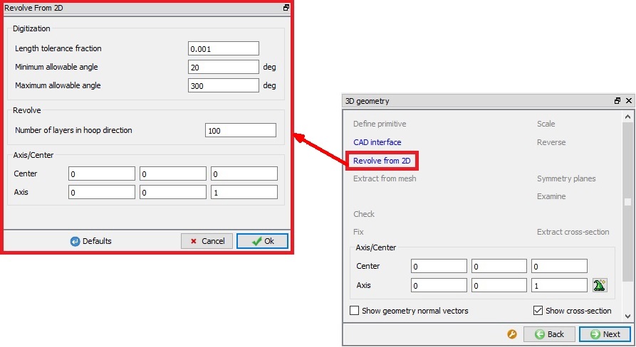
Workpiece- Ring 3D Geometry page
###
Importing 3D Geometry
If user has loaded a 3D geometry of the workpiece from a file, then ![]() option can be used to extract the cross-section from the 3D Geometry and use it to revolve into 3D Geometry.
option can be used to extract the cross-section from the 3D Geometry and use it to revolve into 3D Geometry.
In case of non-uniform ring object, user can import 3D Geometry and visit 3D Mesh page directly to generate 3D Mesh and retain non-uniformity in the workpiece.
If user wants to extract cross-section for a non-uniform ring object, then user can go back to Workpiece – object page and use ![]() from there to generate workpiece 3D geometry with average cross-section.
from there to generate workpiece 3D geometry with average cross-section.
Generating 3D Mesh
Once the 2D Cross-section and 3D geometry are define user can generate 3D mesh. The user must define the number of revolving sections along the hoop’s direction to generate 3D mesh, see Fig. 42.1.24. Depending on the geometry of the workpiece user can select the “Revolving method” to generate workpiece 3D Mesh.
-
Revolve with constant cross-section dimension: This option is used to generate the 3D mesh if the workpiece is having uniform cross section. 2D Cross-section must be defined or extracted in case of imported object/geometry. User can view the cross-section using “Show cross-section” checkbox.
-
Revolve to fit 3D shape: This option is used to generate the 3D mesh for non-uniform cross section ring. 3D Mesh will be generated using the 3D geometry/mesh imported as shown in Fig. 42.1.25. When this option is used, 2D cross-section is extracted automatically and revolved with varying cross section shape.
Revolving Parameters: “Number of revolving sections” along the hoop’s direction can be defined here.
Generate Mesh: User need to click on ![]() button to generate 3D Mesh based on the settings defined.
button to generate 3D Mesh based on the settings defined.
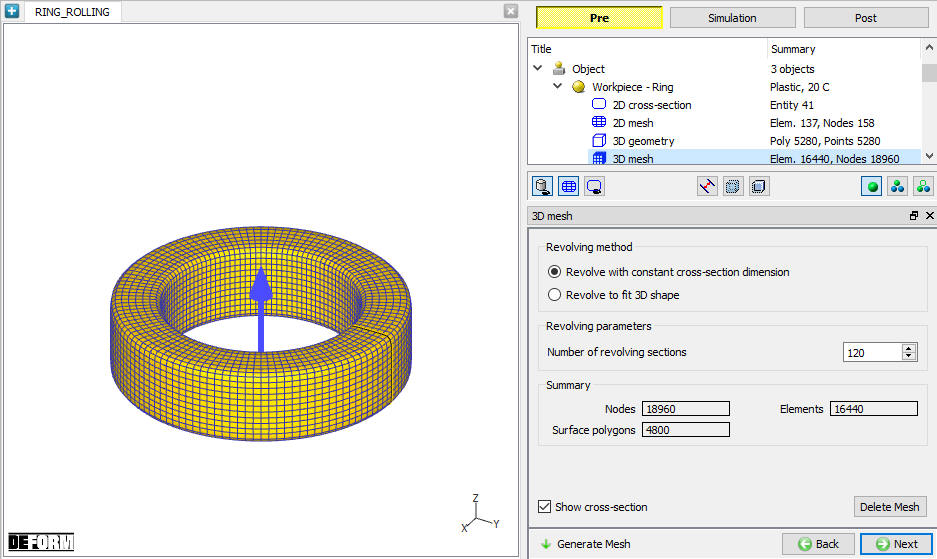
3D Mesh generation using revolve with constant cross-section dimension
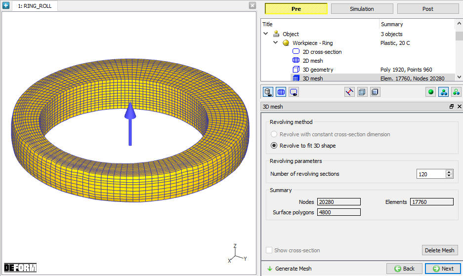
3D Mesh generation using revolve to fit 3D shape
Orientation
If the imported object axis is inclined to +Z axis, then user can align the axis to +Z axis using ![]() button. The orientation angle is automatically calculated and displayed as as shown in the Fig. 42.1.26.
button. The orientation angle is automatically calculated and displayed as as shown in the Fig. 42.1.26.
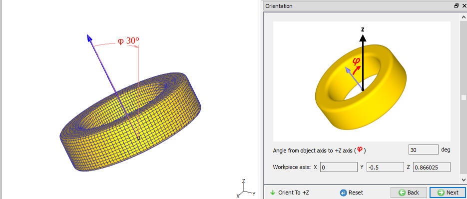
Workpiece Orientation page
Material Page
In material page, all the materials added to material list are displayed (as shown in Fig. 42.1.27.). User can select the required material to assign it to respective object. If the desired material is not available in the list, then the user can load the material in object material page using Import Material data from a File ![]() or Using Load form Library option
or Using Load form Library option ![]() . User can also create new material if the material is not available in DEFORM library using
. User can also create new material if the material is not available in DEFORM library using ![]() . User can delete the material from list using
. User can delete the material from list using ![]() or edit the material data using
or edit the material data using ![]() . Modified / newly defined Material can be saved using
. Modified / newly defined Material can be saved using ![]() ,
, ![]() .
.
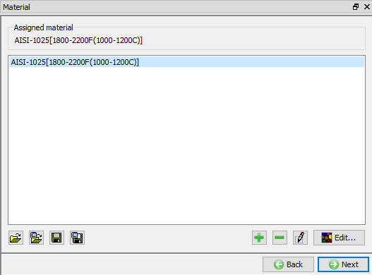
Assigning the material to workpiece
Workpiece BCC
In Boundary conditions page, user can assign various boundary constraints to an object. Boundary conditions specify how the boundary of an object interacts with other objects and with the environment. Commonly used boundary conditions are heat exchange with the environment for simulations involving heat transfer, symmetry and velocity as shown in the Fig. 42.1.28. BCCs are automatically defined while generating 3D Mesh based on the Simulation setup in Ring Rolling Template, if user wants to modify this then options available in this page can be used. For more information on these options please refer 14. Boundary Conditions.
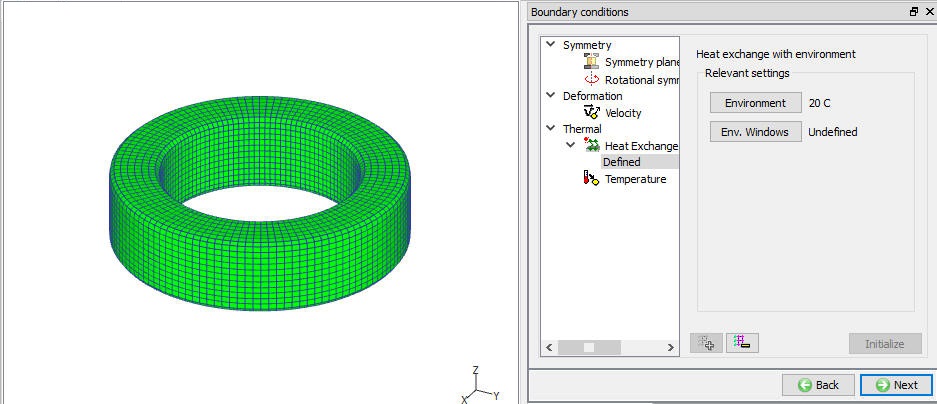
Workpiece BCC
Property
Miscellaneous object parameters, which affect either thermo-mechanical behaviour of the object or numerical solution behaviour are specified in the Object-Properties window. (See Fig. 42.1.29.). Volume compensation is used most in Ring Rolling and can be activated by selecting one of the options under “Target Volume” and calculating current object volume using ![]() button. For more information, please refer 16. Object properties.
button. For more information, please refer 16. Object properties.
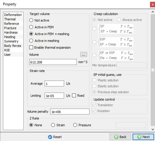
Property page
Initialize
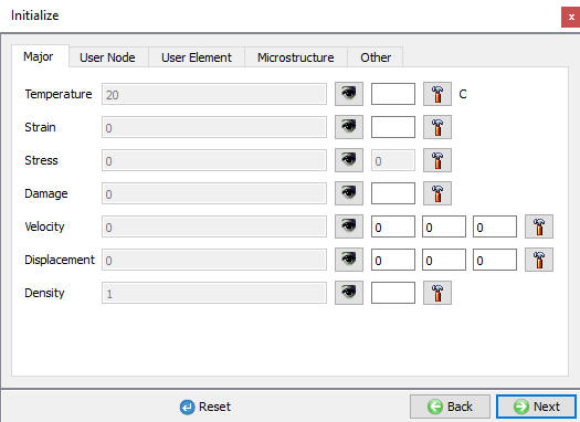
In Initialize window, few state variables that are commonly used such as temperature, strain, stress, damage, velocity, displacement, density and microstructure grain size and particle size are made available for initialization. In multiple ring rolling operation if user wants to initialize the temperature, strain or grain size then user can use this initialization page.
User can initialize the values for these state variables by defining in the field next to it and clicking on ![]() button. Fig. 42.1.30. shows various state variables that are available in Initialize window. Depending on the type of state variable, user can also initialize them from Node and Element data windows. For more information on how to initialize state variables in Node and Element windows, please refer 17.1 Node data window and 11.2 Element data window.
button. Fig. 42.1.30. shows various state variables that are available in Initialize window. Depending on the type of state variable, user can also initialize them from Node and Element data windows. For more information on how to initialize state variables in Node and Element windows, please refer 17.1 Node data window and 11.2 Element data window.
Initialize page
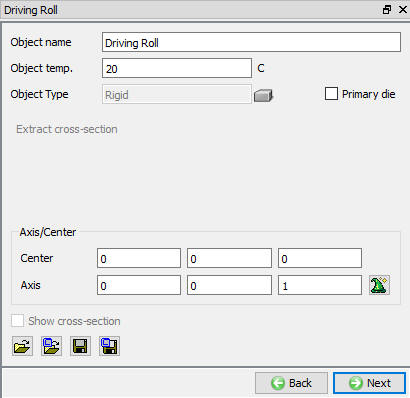
Defining Driving Roll
Driving roll is a rigid object in Ring Rolling template. The temperature, center and axis can be set in Driving roll object page as shown in Fig. 42.1.31. If the simulation setup type is of non-isothermal and temperature calculations are done even on rolls then Driving Roll must have mesh to calculate temperature of this object. The driving roll geometry definition and mesh definition is similar to the workpiece. For more information on defining geometry and mesh please refer 42.1.6. Defining Workpiece-Ring Object, 42.1.7. Defining 2D Cross-section, 42.1.8. Generating 2D Mesh, 42.1.9. Generating 3D Geometry, 42.1.10. Generating 3D Mesh and 42.1.12. Material Page.
Driving Roll page
###
Defining Driving Roll Orientation
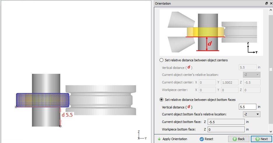
If the Driving roll that is created or imported is not at right place, then Orientation page under Driving roll object in object tree can be used to position the roll with respect to workpiece along the axis as shown in the Fig. 42.1.33. User can position roll with respect to object center or bottom face. Based on the parameters defined the current object is moved and interference positioned with workpiece, the interference direction depends on the current object type like Driving Roll, Pressure Roll and Axial Roll.
Set relative distance between object center: This option is used to position the driving roll by defining the vertical distance between the current object center and workpiece center along with direction of measurement using “Current object’s relative location” (+Z or -Z), see Fig. 42.1.33.
Set relative distance between object bottom faces: This option is used to position the driving roll by defining the vertical distance between the current object bottom face and workpiece bottom face along with direction of measurement using “Current object’s relative location” (+Z or -Z), see Fig. 42.1.38.
Reset : User can use ![]() button to go back to the original position before entering the orientation page.
button to go back to the original position before entering the orientation page.
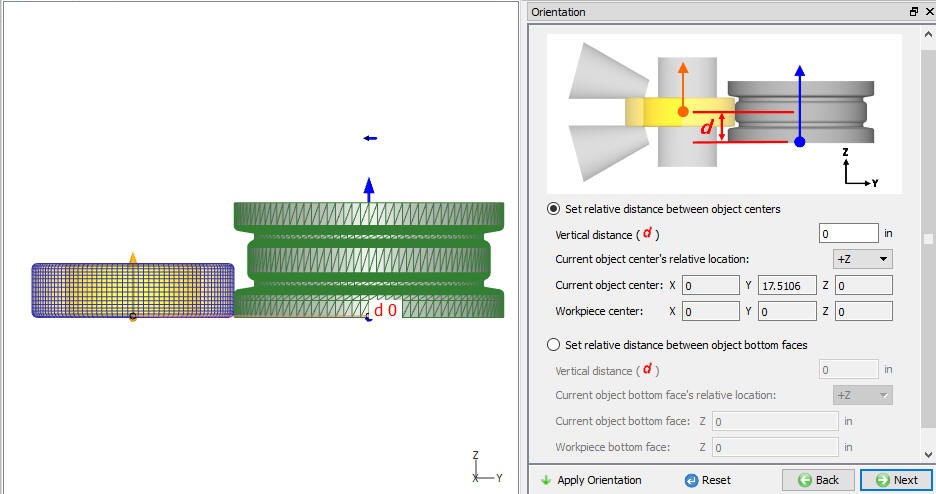
Driving Roll before orientation
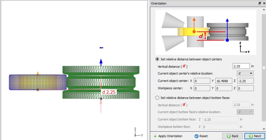
Driving Roll after orientation
Defining Driving Roll Movement
In Ring Rolling template the Driving Roll can have both translation and rotational movement as shown in Fig. 42.1.34. Movement must be defined using options available in Guided Mode.
Translation movement can be defined as speed or Force. Speed or Force can be defined as constant, Function of time or Function of Diameter (Ring External Diameter). The movement direction is fixed in Ring Rolling template and cannot be modified, see Fig. 42.1.34.
Rotational movement can be defined as Angular Velocity or Torque. Angular velocity or Torque can be defined as constant, Function of time or Function of angle (rotation angle), see Fig. 42.1.35.
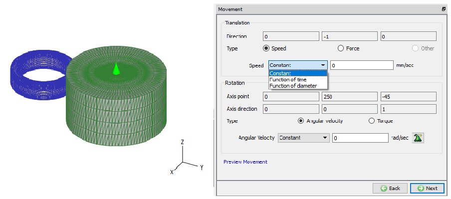
Translation Movement Controls (For Guided Mode)
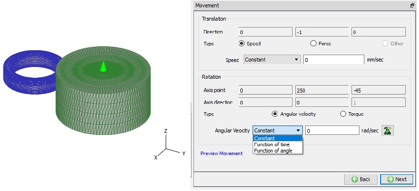
Rotation Movement Controls (For Guided Mode)
Defining Pressure Roll
Pressure roll is a rigid object in Ring Rolling template. The temperature, center and axis can be set in Pressure roll object page as shown in Fig. 42.1.36. If the simulation setup type is of non-isothermal and temperature calculations are done even on rolls then Pressure Roll must have mesh to calculate temperature of this object. The pressure roll geometry definition and mesh definition are similar to the workpiece. For more information on defining geometry and mesh please refer 42.1.6. Defining Workpiece-Ring Object, 42.1.7. Defining 2D Cross-section, 42.1.8. Generating 2D Mesh, 42.1.9. Generating 3D Geometry, 42.1.10. Generating 3D Mesh and 42.1.12. Material Page.
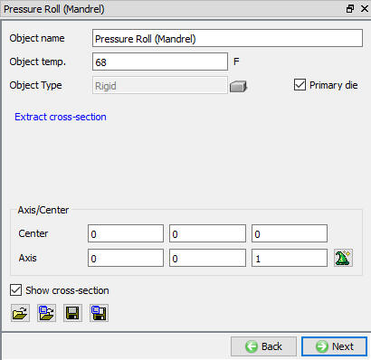
Pressure Roll page
###
Pressure Roll Orientation
Similar to Driving Roll, Pressure Roll can be positioned with respect to workpiece as shown in the Fig. 42.1.37 & Fig. 42.1.38. For more information on positioning options please refer Driving Roll Orientation.
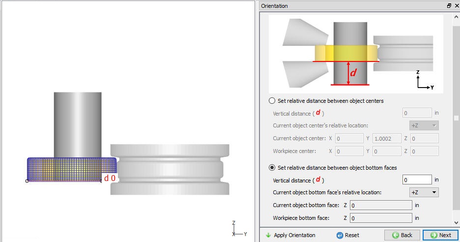
Pressure Roll before orientation
Pressure Roll after orientation
###
Defining Pressure Roll Movement
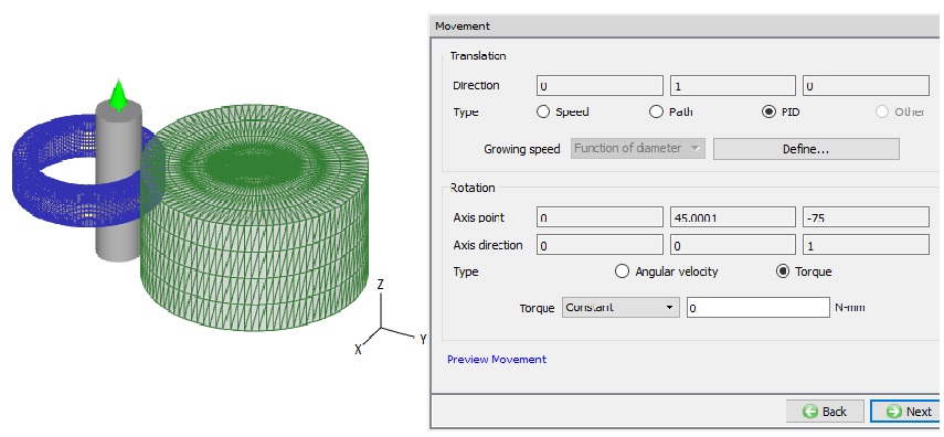
Similar to a Driving Roll, the Pressure Roll can have both translation and rotational movement as shown in Fig. 42.1.39. Movement must be defined using options available in Guided Mode.
Translation movement can be defined as speed, Path or PID. Speed can be defined as constant, Function of time or Function of Diameter. Path can be defined “Stroke(Y) as Function of Time”. PID type movement can be used to define the movement based on the ring growth and can be defined as “Ring growing speed as Function of diameter”. The direction of movement is fixed in Ring Rolling template and cannot be modified, see Fig. 42.1.39.
Rotational movement can be defined as Angular Velocity or Torque. Angular velocity or Torque can be defined as constant, Function of time or Function of angle (rotation angle), see Fig. 42.1.39.
Pressure Roll movement page
Defining Axial Roll
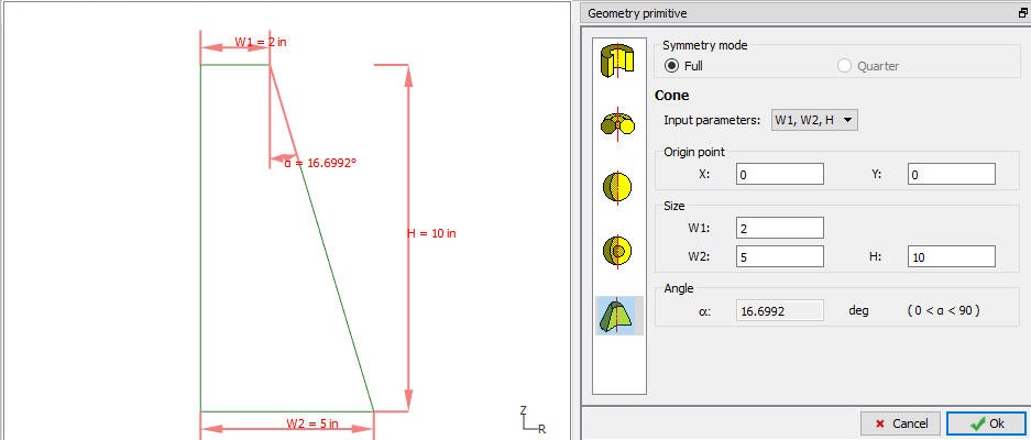
Axial roll is a rigid object in Ring Rolling template. The temperature, center and axis can be set in Axial roll object page as shown in Fig. 42.1.40. If the simulation setup type is of non-isothermal and temperature calculations are done even on rolls then Axial Roll must have mesh to calculate temperature of this object. Most commonly the axial rolls geometry can be created using “Cone” primitive available in 2D primitives, see Fig. 42.1.41. The axial roll geometry definition and mesh definition is similar to the workpiece. For more information on defining geometry and mesh please refer 42.1.6. Defining Workpiece-Ring Object, 42.1.7. Defining 2D Cross-section, 42.1.8. Generating 2D Mesh, 42.1.9. Generating 3D Geometry, 42.1.10. Generating 3D Mesh and 42.1.12. Material Page.

Axial Roll page
Axial Roll primitive page
Axial Roll Orientation
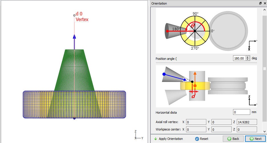
In Axial roll Orientation page, the user can define the Axial roll position angle and horizontal distance as shown in Fig. 42.1.42., then click on ![]() . This Orientation page can be used to position the Axial roll along the Ring circumference in hoops direction by specifying angle in Rotation angle filed and along the ring width by specifying the Horizontal distance between the cone end and ring center as shown in Fig. 42.1.43.
. This Orientation page can be used to position the Axial roll along the Ring circumference in hoops direction by specifying angle in Rotation angle filed and along the ring width by specifying the Horizontal distance between the cone end and ring center as shown in Fig. 42.1.43.
Axial Roll before orientation
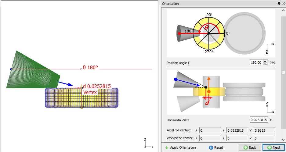
Axial Roll after orientation
Axial Roll Movement Page
Similar to Driving roll movement controls, user can define both Translation movement and Rotational movement to Axial rolls as shown in Fig. 42.1.44.
Translation movement can be defined as speed, Force or Path. Speed or Force can be defined as constant, Function of time or Function of Diameter, whereas Path can be defined as Function of Time or Function of diameter, see Fig. 42.1.44.
Rotational movement can be defined as Angular Velocity or Torque. Angular velocity or Torque can be defined as constant, Function of time or Function of angle (rotation angle), see Fig. 42.1.44.
-
Automatic Radial Movement: Axial rolls can move automatically in the radial direction such that the vertex of axial roll is always located on the center of ring along with the expansion of the ring. In order to activate this function, user need to check “Automatic radial movement w.r.t. the expansion of workpiece” check box.
-
Adaptive Rotational Movement: If user check the “Adaptive rotational movement control” check box, then axial rolls rotate according to the rotation of ring without any slippage.
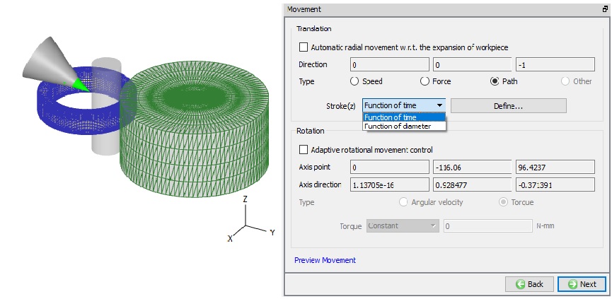
Axial Roll Movement Page
Axial Roll #2 Page
For the second axial roll user can use the “Copy Axial Roll #1” option, so all the data of Axial Roll #1 is copied to Axial Roll # 2 object (See Fig. 42.1.45.) and is positioned automatically in the -Z direction, see Fig. 42.1.46.
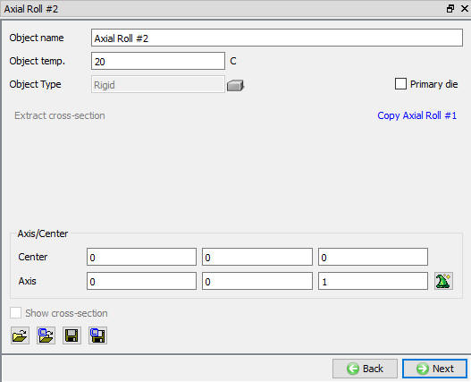
Axial Roll #2 page
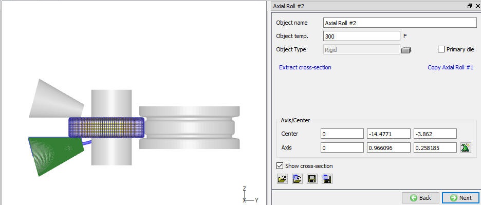
Copying Axial Roll #1 to Axial Roll #2
Positioning
When user wants further modification in any of these objects position even after using orientation, then user can use Position objects button in Positioning page. Various positioning options are available to position the objects as shown in Fig. 42.1.47., for more information on these options please refer 19. Object positioning.
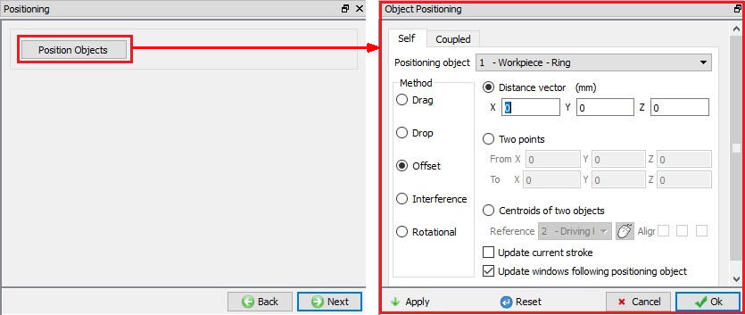
Object Positioning Controls
Scheduled positioning
When user is not sure about the location of an object as in case of Read from DB objects, scheduled positioning will help to position the objects accurately. Schedule positioning allows the user to define the positioning for objects in Integrated Manufacturing Process setup for successive operations for which DB is not generated so that the objects are positioned before generation of DB while running simulation in Batch mode (See Fig. 42.1.48.).
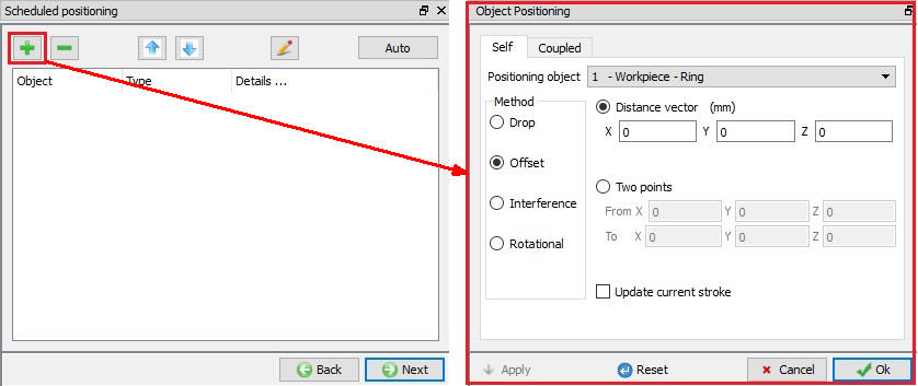
Scheduled positioning options
Contact
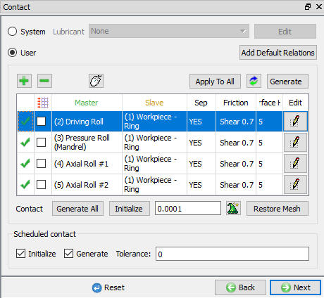
The user can define the contact between the Workpiece and other roll objects by defining the inter object relations as shown in Fig. 42.1.49. User must define friction and Interface heat transfer co-efficient for non-isothermal rolling processes and friction value for isothermal rolling process.
System : By selecting this radio button, system assigns default inter-object relationships. Also, user can add the lubricants if necessary, by selecting Add New from pull down menu and clicking on ![]() button or user can load the required lubricants from the library for the simulation.
button or user can load the required lubricants from the library for the simulation.
User: By default, user radio button will be selected for Ring Rolling operation. User can add relationships by clicking on ![]() button as shown in Fig. 42.1.49. User can modify the value of each relation by selecting it and clicking on
button as shown in Fig. 42.1.49. User can modify the value of each relation by selecting it and clicking on ![]() button. User can use
button. User can use ![]() to assign same values to all relations. User can click on to calculate contact tolerance. User can click on
to assign same values to all relations. User can click on to calculate contact tolerance. User can click on ![]() to generate contact relation. User can turn on check box next to contact relation to define sticking contact. For more information please refer, 20. Inter-Object Data Relations.
to generate contact relation. User can turn on check box next to contact relation to define sticking contact. For more information please refer, 20. Inter-Object Data Relations.
Contact Page
Stopping Controls for Ring Rolling Simulation
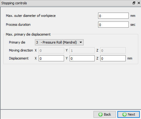
User can stop the Ring Rolling simulation using the settings available in Stopping controls page, as shown in the Fig. 42.1.50.
Max. outer diameter of workpiece : This option is displayed based on the diameter definition defined in the workpiece object page, we are not defining stopping control in workpiece object page(refer Diameter measuring position), if the explicit diameter measuring position has been defined, the display here will show correspondence information. If diameter measuring position is not defined, we will show max outer diameter of workpiece which is the default diameter definition.
Process duration: The simulation stops after completing the defined process duration.
Max. primary die displacement : User can select one of the rolls as “Primary Die” using pull down menu and define maximum displacement at which simulation should stop. Moving direction for the selected primary die will be displayed. The simulation stops after primary die exceeds the defined displacement.
Stopping Controls Page
Step and remeshing controls for Ring Rolling
Ring Rolling simulation can be controlled based on time step and saved based on rotational degree frequency. User can also control the frequency of temperature calculation for non-isothermal simulations and schedule remeshing. Step and remeshing controls are as shown in Fig. 42.1.51.
Number of steps: Number of steps to be simulated can be defined here. User can define more number of steps and use the stopping criteria to stop the simulation earlier due to stopping.
Rotation increment to save: When a simulation runs, every step must be computed, but does not necessarily need to be saved in the database. Storing more steps will preserve more information about the process, consequently it will require more storage space. Data from the simulation will be written to DB based on the frequency of Rotational increment defined here.
Max. allowable Time Step: User need to specify the time step which will be used as the time interval per step for various calculation.
Temperature computation: The user can set the temperature calculations frequency to same as deformation or at specific rotation angle frequency by using the options under Temperature Computation tab.
Remeshing controls: User can schedule remesh for workpiece after specified number of revolutions to maintain good workpiece shape in case of complex geometries.
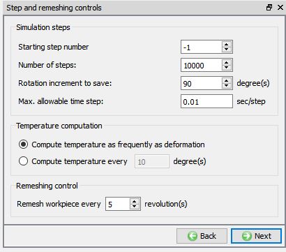
Steps and remeshing controls
Simulation controls
In this page, user can define constraints to stabilize the workpiece while revolving during simulation and few advanced controls as shown in Fig. 42.1.52. and Fig. 42.1.53. The data defined in this page will be written to DEF_RRE.DAT file.
Stability Control
Workpiece Center control: If user notices any stability issues with workpiece/ring during simulation then user can constraint the rotation and translation of the workpiece in the specified directions to maintain the workpiece center as shown in Fig. 42.1.52.
Virtual Table: User can also add a virtual table at top or bottom by checking respective check box and specifying the distance of virtual table location from top / bottom surface of the workpiece, see Fig. 42.1.52. Current Z co-ordinate value in respective direction is displayed.
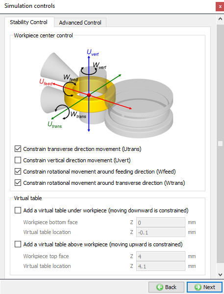
Simulation Controls- Stability Controls
Advanced Control
Node Penetration check: User can define the frequency of steps to verify if nodes from roll are penetrating into workpiece/ring, see Fig. 42.1.53. When the value is defined as 0 or negative, the system does not check for penetration. When the value is defined between 1 and 50, the system checks for penetration at every 50 steps. When the value is defined larger than 50, then the system checks at frequency of defined steps
Contact Search: User can also specify angle for contact search to improve the Solution speed, see Fig. 42.1.53. The search angle starts from the inlet side between Driving Roll and Pressure Roll (mandrel).
Enforce Ring Rotation: If the ring object is not rotating properly then user can check “Enforce to rotate workpiece when it does not rotate well at certain steps” to make small corrections to the ring rotation during the ring rolling process, see Fig. 42.1.53.
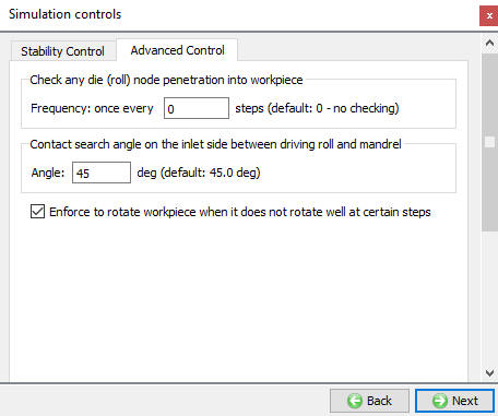
Simulation Controls - Advanced Controls
Generate DB
Once user is completed with setting up of Ring Rolling Problem then user can use this page to check the data defined and generate database. From v12.0.2, we can observe the Operation Simulation setup summary. (See Fig. 42.1.54.)
Check Data![]() : It checks the Data. If Data is correct, we can generate DB. But while checking Data if it gives any errors or warnings then it should be corrected before generating Database. Errors will not allow the database to be generated while warnings will allow the DB to be generated.
: It checks the Data. If Data is correct, we can generate DB. But while checking Data if it gives any errors or warnings then it should be corrected before generating Database. Errors will not allow the database to be generated while warnings will allow the DB to be generated.
Generate Database![]() : By clicking on this button, it generated the Database for the setup. (See Fig. 42.1.54.)
: By clicking on this button, it generated the Database for the setup. (See Fig. 42.1.54.)
Append Key file: Any information that is not defined in the template but still applicable to the process can be loaded as .key file. This option is also useful in the cases where only few values needs to be changed then those values can be defined as .key file and store in specified path, when only necessary values in .key file can be changed, and simulation can be resubmitted to study the effect of the change in parameters.
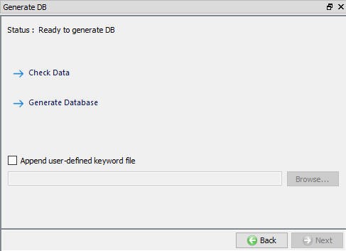
Generate DB page
Setting up Ring Rolling Operation in Batch mode
Ring Rolling operation can be setup in batch mode as part of multiple operations in Integrated Manufacturing environment. User can add Ring Rolling operation in sequence with other operations as shown in Fig. 42.1.55.
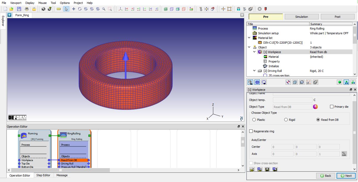
Workpiece- Ring object type is Read from DB
Workpiece– Ring is Read from DB
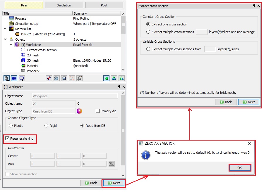
The user is provided with Regenerate ring check box when the object is read from DB as shown in the Fig. 42.1.56. If the user selects the “Regenerate Ring” check box than in operation tree ![]() , 2D Mesh and 3D Mesh pages are added (see Fig. 42.1.56.) which can be used to Ring shape and mesh. User can set the axis and center. If axis is not set and values are “0” then Z direction will be set as axis and a pop-up “Zero Axis Vector” appears when user leaves object page informing about direction set (0,0,1) as shown in the Fig. 42.1.56.
, 2D Mesh and 3D Mesh pages are added (see Fig. 42.1.56.) which can be used to Ring shape and mesh. User can set the axis and center. If axis is not set and values are “0” then Z direction will be set as axis and a pop-up “Zero Axis Vector” appears when user leaves object page informing about direction set (0,0,1) as shown in the Fig. 42.1.56.
When Ring is “Read from DB” and user clicks ![]() button in object page then “Extract cross-section” page is opened as shown in Fig. 42.1.56.
button in object page then “Extract cross-section” page is opened as shown in Fig. 42.1.56.
###
Extract Cross-section for Read from DB object
The user is provided with Constant cross section and Variable cross sections options to extract the cross section from the Workpiece as shown in the Fig. 42.1.56.
Constant Cross Section: When constant cross-section is selected then system generates ring with constant cross-section. If the output from previous operations is expected to generate a uniform ring, then user can use “Extract one cross-section” option to generate ring with constant cross-section. If the output from previous operations is expected to generate a non-uniform ring, then user can extract multiple cross-sections from specified number of layers, and use the average size as cross-section using “Extract Cross-section from Layers()/slices and use their average”. If the mesh type of the “Read from DB” object is brick mesh, then numbers of layers is decided by the system.
Variable Cross Section: If the output from previous operations is expected to generate a non-uniform ring and user would like to generate ring with non-unform cross-section then this option can be used. User can define to extract multiple cross-sections and retain them to generate non-uniform ring using “Extract Cross-section from Layers()/slices”. If the mesh type of the “Read from DB” object is brick mesh, then numbers of layers is decided by the system.
Extracting the cross section to regenerate the Ring
###
Generating the Workpiece 2D Cross-section mesh
Since the cross-section is extracted from the Object which is “Read From DB” it is always necessary to generate a new 2D Mesh when user is regenerating ring shape. User can turn on select “Perform remesh before this operation” check box as shown in the Fig. 42.1.57. and define 2D mesh settings to be used in new mesh generation. For more on mesh settings refer 13.1.2D Mesh Generation.
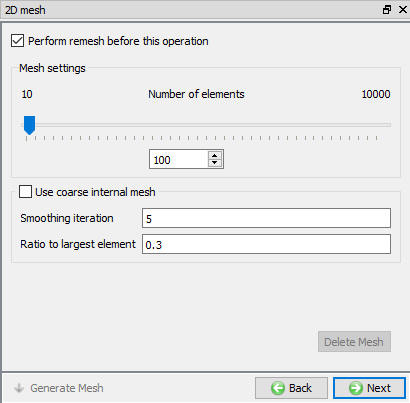
2D Mesh page for the Read from DB Object
Generating Workpiece 3D Mesh
User need to generate the 3D Mesh for the workpiece if user is regenerating ring shape for a “Read from DB” object. Depending on the type of cross-section selected in the Workpiece object page, see Extract Cross-section for Read from DB object, the revolving method is automatically selected. User can define the number of revolving sections along the hoop’s direction in 3D mesh settings as shown in the Fig. 42.1.58.
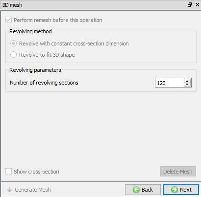
3D Mesh page for the Read from DB Object
Running Simulation
Once user made all necessary changes to extract cross-section and generate mesh during simulation for workpiece which is “Read from DB” user can save the project and shift to simulation tab by clicking on ![]() button above operation tree. User can click on
button above operation tree. User can click on ![]() label and choose appropriate option from the pop-up to start the simulation.
label and choose appropriate option from the pop-up to start the simulation.