9.10. Output Controls 
9.10.1. Elemental/Nodal [2D, 3D]
9.10.2. Strain [2D, 3D]
9.10.3. Nodal heat [2D, 3D]
Elemental/Nodal [2D, 3D]
The output control that is available to the user is intended to improve the state variable representation in the analysis domain and minimize the interpolation error involved in the remeshing procedures. Such representation can also better maintain the local gradients of the state variables compared to the existing the element based representation. In the current version, the user can choose to represent damage, strain and stress state as Element+Nodal data. This means in addition to the currently available element data, the user can store these variables as nodal variables. From v11 onwards, the state variables can also be calculated at integration points.
From V14.0, the Output Control tab has been removed from Advanced options and made available as separate tab as shown in Fig. 9.10.1. In addition to the existing Stress, Strain and Damage state variables, Heat generated at the nodal level can be calculated.

Elemental/Nodal output selection page
Strain [2D, 3D]
The wide selection of strain components that can be stored by the user depends upon the analysis and object type. These options for a typical elasto-plastic object enable user to store plastic, elastic and total strains. For non-isothermal models with elasto-plastic objects, additionally thermal volumetric strains can also be stored for each stored step of the simulation. When transformation is turned on, the strain components that are produced due to phase transformation can be stored as well.
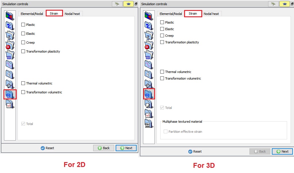
Strain output options
Once set in the Pre-Processor, each of these strain components (STNOUT) as shown in Fig. 9.10.3. are available in post processing for point tracking, contour plots and other normal display options (See Fig. 9.10.4.).
These additional nodal and element variables can be accessed from the corresponding nodal and element dialogs as shown in Fig. 9.10.5.
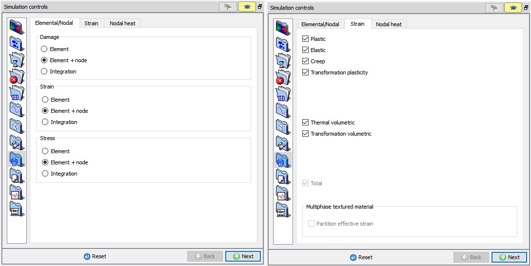
Setting the additional strain components and element + node data
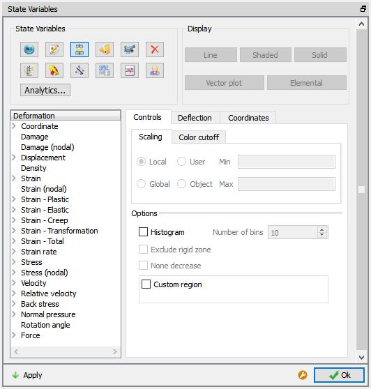
State variable list for additional strain components and Elemental+Node data
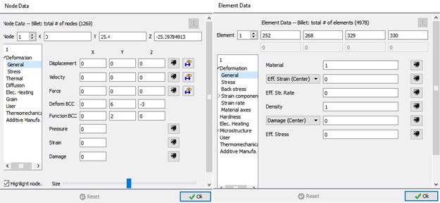
Enhanced node and element dialogs including additional nodal variables and strain components.
Nodal heat[2D, 3D]
From v14.0, Nodal heat option added under Simulation controls.
Nodal heat output can be created either as time integrated or for the current step. These options are available to the user when Heat transfer mode check box is turned on in Main settings page.
By default, Time integrated nodal heat output is activated and cannot be deactivated.
Nodal heat output due to various factors during forming at a particular step can be captured as Normalized nodal heat components. Currently, we can plot nodal heat output due to Deformation and Friction along with the Total output.
-
Total : When we turn on Total check box, during simulation Total nodal heat at the current step will be calculated and saved in database.
-
Deformation : When we turn on the Deformation check box, during simulation nodal heat generated due to deformation at the current step will be calculated and saved in database.
-
Friction : When we turn on Friction check box, during simulation nodal heat generated due to friction at the current step will be calculated and saved in the database.
According to the selection of Normalized nodal heat components in Pre, under State variable- Thermal tab (see Fig. 9.10.6.), we can observe the selected Normalized nodal heat components outputs (See Fig. 9.10.7).
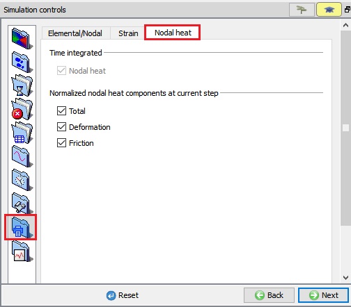
Nodal heat output selection page
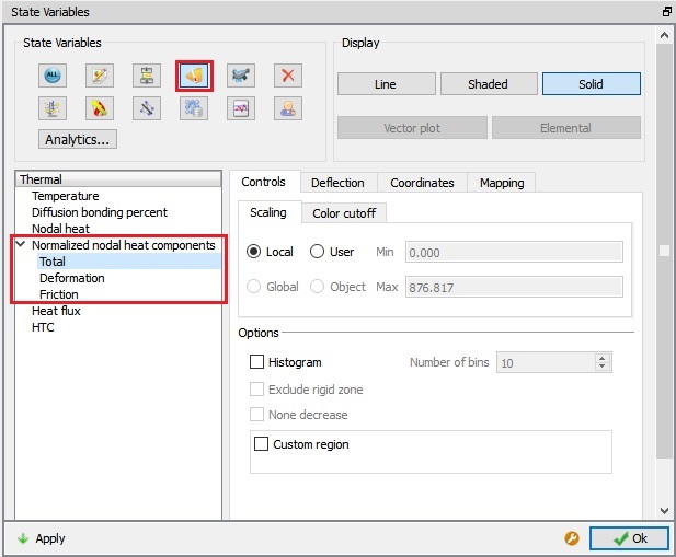
Normalized nodal heat components options.
Related Topics:
9.1. Simulation type Settings
9.2. Defining Step
9.3. Stopping Controls
9.4. Remesh Criteria
9.5. Solver Settings
9.6. Process Conditions
9.7. Advanced Options
9.8. Control Files