45.1. Boolean Operator
45.1.1. Defining 2D Boolean Operator
45.1.1.1. Add 2D Boolean operation
45.1.1.2. Pass objects for subsequent operations across boolean operator
45.1.1.3. Add objects
45.1.1.4. Define Boolean object
45.1.1.5. Define Cutter object
45.1.1.6. Define Cutter geometry
45.1.1.7. Position cutter
45.1.1.8. Preview Boolean
45.1.1.9. Generate Database
45.1.1.10. Continue with subsequent operation
45.1.1.11. Post processing 2D Boolean results
45.1.2. Defining 3D Boolean operator
45.1.2.1. Add Objects
45.1.2.2. Defining Boolean object
45.1.2.3. Define Cutter object
45.1.2.4. Define Cutter geometry
45.1.2.5. Position cutter
45.1.2.6. Preview Boolean
45.1.2.7. Generate Database
45.1.2.8. Post processing the 3D boolean results
45.1.2.9. Continuing the further operations
Defining 2D Boolean Operator
Boolean operation normally added as subsequent operation in multiple operations to boolean the unwanted material from the object. 2D Boolean is explained in this manual for extrusion example, so that total extrusion divided into 3 stages and after 1st and 2nd stage outside the interested area of extruded material is booleaned to reduce the computational time of simulation.
Before going to the add the Boolean operation first open the Integrated Manufacturing Process in SI units ![]() add 2D Forming operation
add 2D Forming operation ![]() import the 2D SI Extrusion example EXTR1_SI.KEY in guided mode as shown in Fig. 45.1.1.
import the 2D SI Extrusion example EXTR1_SI.KEY in guided mode as shown in Fig. 45.1.1. ![]() select Step branch from operation tree and set number of steps to 300
select Step branch from operation tree and set number of steps to 300 ![]() click
click ![]() and generate DB.
and generate DB.

Import and setup 2d extrusion example
Add 2D Boolean operation
After the 2D operation setup database generation add 2D Boolean operator from MO explorer Simulation operator group as shown in Fig. 45.1.2.
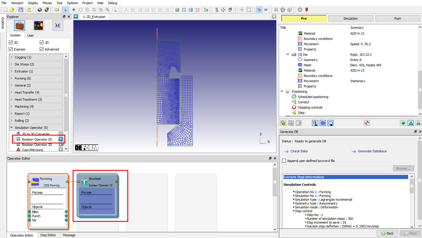
Add 2d Boolean operation
Add another 2D forming operation after 2d Boolean operation as shown in Fig. 45.1.3. to continue the further extrusion taking less simulation computational time.

Add forming operation after Boolean operation
Pass objects for subsequent operations across Boolean operator
Pass first operation workpiece object to all operations as shown in Fig. 45.1.4., similarly pass remaining objects to all operations. If user is continuing the operations after Boolean with previous objects other than first object then those objects must be passed to Boolean operation before adding objects in Boolean operation.
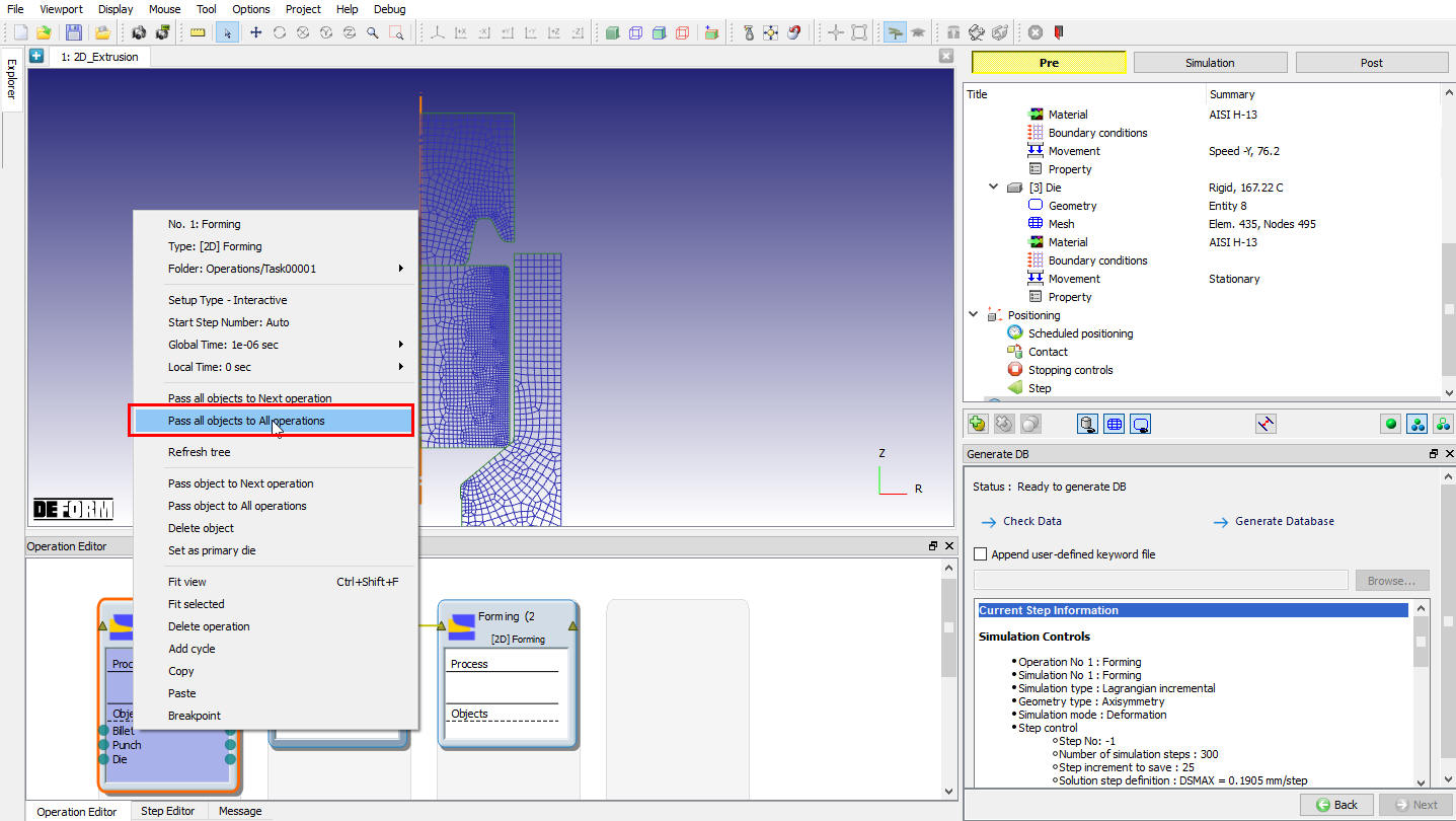
Passing workpiece object to all operations
After passing all objects in operation editor user can observe the link established for all the three objects across the operations as shown in Fig. 45.1.5. Select the boolean operation in operation editor to open boolean operation as shown in Fig. 45.1.5.

Open Boolean operation
Add objects
System automatically selects the workpiece or first object as boolean object as shown in Fig. 45.1.5. For Cutter new object can be added by selecting the Add new object option (See Fig. 45.1.5.) and clicking ![]() to the object window as shown in Fig. 45.1.6. Any object from previous operation can also be selected as cutter object.
to the object window as shown in Fig. 45.1.6. Any object from previous operation can also be selected as cutter object.

A new object added for Cutter object in operation tree
Define Boolean object
In Object window (See Fig. 45.1.6. ) no need to change any settings, it gives the details about the object type. For boolean object only Deformation boundary conditions constrains (BCC) and initialize state variable windows will be available, user can change the BCC in schedule before Boolean by checking “Redefine BCC” check box (See Fig. 45.1.7.). For more details on different BCC definition and its definition refer 14. Boundary Conditions.

Schedule BCC definition window for boolean object
Similarly state variables can be initialized before Boolean by checking the respective available check boxes as shown in Fig. 45.1.8. For more details on state variables initialization refer 17. Object Data Initialize.

Schedule state variables initialize window for Boolean object
In this example no need to change or select any option for Boolean object (workpiece) so select Cutter object to continue setup.
Define Cutter object
Cutter object can be named and imported from DEFORM previous project DB or Keyword files using Import object from a file ![]() and Load object from library
and Load object from library ![]() options as shown in Fig. 45.1.9.
options as shown in Fig. 45.1.9.

Cutter object window
Define Cutter geometry
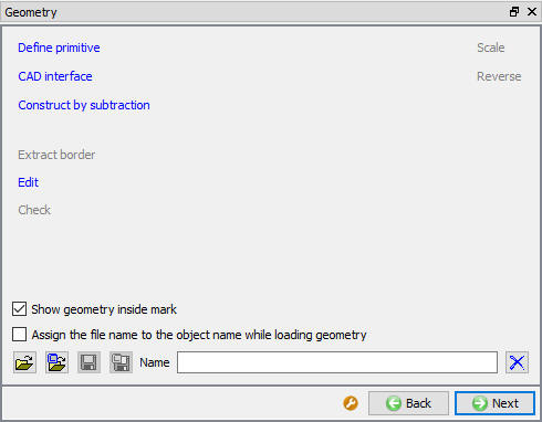
Simple Cutter geometry can be created from the geometry primitives or 2D geometry editor options as shown in Fig. 45.1.10. Even the 2D geometries can be imported from GEO, IGS and DXF formats. Based on the geometry type of previous operation respective geometry primitives will be available in boolean operation. As cutter object does not need the mesh Extract border from mesh option will not activate.
For more details about the geometry available option refer 12.1. 2D Geometry Data Defining and 12.2. 2D Geometry Data Editing. In this example we will create 2D geometry using ![]() option as shown in Fig. 45.1.11.
option as shown in Fig. 45.1.11.
Cutter geometry definition window

Cutter geometry creating from Edit option
Position cutter
Cutter can be positioned in exact location by using the positioning options, this can be accessed from ![]() button as shown in Fig. 45.1.12.
button as shown in Fig. 45.1.12.

Object positioning window
Preview Boolean
Preview Boolean window is provided for future development when this operation supports interactive mode setup to visualize how the booleaned object looks like. This button will be deactivated for the read from DB object type. As this operation currently supports only batch mode, so only Read from DB object will become boolean object hence preview boolean will be deactivated in this mode (See Fig. 45.1.13.).

Preview Boolean window
Generate Database
User has to generate the database in case if previous operation is simulated, if not database will generate while running after completion of previous operation automatically.(See Fig. 45.1.14.)
Generate Database : By clicking on this ![]() button, it generates the Database for the setup.
button, it generates the Database for the setup.
Append Key file: Any information that is not defined in the wizard but still applicable to the process can be loaded as .key file. This option is also useful in the cases where only few values needs to be changed then those values can be defined as .key file and only .key file can be changed and simulation can be resubmitted.
User can observe the cutter object placed in the extrusion direction so that after first extrusion operation certain out of interest extruded workpiece portion from tip will be booleaned.

Database generation window
Continue with subsequent operation
After Boolean subsequent operations can be added and continue the setup. In this example further extrusion operation can be setup by opening the third operation and adding default inter-object relations and selecting the total number of steps to 100 and defining the step increment, that is 0.1905mm stroke increment (See Fig. 45.1.15.).

Continue with subsequent operation after Boolean
After this setup to repeat the similar cycle of Booleaning the uninterested area and continuing the extrusion to reduce the computational time user can add the Cycle operation. To add the cycle select Boolean and second forming operation and using right mouse button option select Add cycles as shown in Fig. 45.1.16. Select the number of cycles as 2, so boolean operation repeats twice after the first and second extrusion operations.

Cycling boolean and forming operation
Post processing 2D Boolean results
After completion of simulation to preform post processing switch to MO post mode by selecting the![]() button as shown in Fig. 45.1.17.
button as shown in Fig. 45.1.17.

Material flow at boolean previous operation last step
Select the last step of the operation previous to boolean and then select the boolean operation step from step browser as shown in Fig. 45.1.17. and Fig. 45.1.18.

Workpiece object after boolean
Defining 3D Boolean operator
3D Boolean is explained in this manual for closed die T-shape forging case which is already simulated, now we need to remove the flash material.
We are adding 3D Boolean operator from explorer as shown in Fig. 45.1.19. and follow as mentioned below.

Add 3D boolean operation after previous operation simulation
Add Objects
Select the boolean operation in operation editor to open boolean operation, system automatically selects the workpiece or first object of previous operation as boolean object and Add New object option for cutter as shown in Fig. 45.1.20.

Adding objects to boolean objects
Clicking ![]() to the object window will add these objects to operation tree as shown in Fig. 45.1.21. Any object from previous operation passed to the boolean operation can also be selected as cutter object.
to the object window will add these objects to operation tree as shown in Fig. 45.1.21. Any object from previous operation passed to the boolean operation can also be selected as cutter object.

A new object added for Cutter object in operation tree
Defining Boolean object
In Object window (See Fig. 45.1.21.) no need to change any settings, it gives the details about the object type. For boolean object only Symmetry and Deformation boundary conditions constrains (BCC) and initialize state variable windows will be available, user can change the Advanced BCC in schedule before Boolean by checking “Redefine BCC” check box (See Fig. 45.1.22.). For more details on different BCC definition and its definition refer 14. Boundary Conditions.

Schedule BCC definition window for boolean object
Similarly state variables can be initialized before Boolean by checking the respective available check boxes as shown in Fig. 45.1.23. For more details on state variables initialization refer 17. Object Data Initialize.

Schedule Initialize window for boolean object
In this example no need to change or select any option for Boolean object (workpiece) so select Cutter object to continue setup.
Define Cutter object
Cutter object can be named and imported from DEFORM previous project DB or Keyword files using Import object from a file ![]() and Load object from library
and Load object from library ![]() options as shown in Fig. 45.1.24.
options as shown in Fig. 45.1.24.

Cutter object window
Define Cutter geometry
Simple Cutter geometry can be created from the geometry primitives or 3D geometry editor options as shown in Fig. 45.1.25. Even the 3D geometries can be imported from GEO, STL, PDA, NAS and UNV formats. For more details about the geometry available option refer 12.3. 3D Geometry Data Defining In this example we will import the 3D geometry for cutter object.

Cutter geometry definition window
Position cutter
Cutter can be positioned in exact location by using the positioning options, this can be accessed from ![]() button as shown in Fig. 45.1.26.
button as shown in Fig. 45.1.26.

Cutter object Positioning window
Preview Boolean
For 3D object, we have two type Boolean method, Geometry based (new method) and Solid mesh based (old method).** For 3D Object Boolean preview button will be active, when we click on ![]() we can observe the preview of boolean workpiece as shown in Fig. 45.1.27. and Fig. 45.1.28.
we can observe the preview of boolean workpiece as shown in Fig. 45.1.27. and Fig. 45.1.28.
- Geometry based (new method) : Using Geometry based option if we do Boolean operation, it will Perform Boolean and then Local Remeshing as per the defined input. This will generate smooth mesh as shown in Fig. 45.1.27.

Geometry based method Boolean preview
- Solid mesh based (old method) : Using Solid mesh based if we do Boolean operation, it will perform boolean and then generate only Solid mesh, please refer Fig. 45.1.28.

Solid mesh method Boolean preview
For more information related to Boolean option refer 18.1. Boolean.
Generate Database
User has to generate the database in case if previous operation is simulated (see Fig. 45.1.29.), if not database will generate while running after completion of previous operation automatically. In this example as the previous operation is simulated ![]() button is activated, so click on
button is activated, so click on ![]() button to generate the database.
button to generate the database.

Database generation window if previous operation is simulated
Generate Database![]() : By clicking on
: By clicking on ![]() button, it generates the Database for the setup.
button, it generates the Database for the setup.
Append Key file: Any information that is not defined in the wizard but still applicable to the process can be loaded as .key file. This option is also useful in the cases where only few values needs to be changed then those values can be defined as .key file and only .key file can be changed and simulation can be resubmitted.
Post processing the 3D boolean results
User has to simulate the DB to perform the boolean operation and then switch to MO post mode by selecting the ![]() button as shown in Fig. 45.1.30.
button as shown in Fig. 45.1.30.

Material flow at boolean previous operation last step
Select the last step of the operation previous to boolean and then select the boolean operation step from step browser as shown in Fig. 45.1.30. and Fig. 45.1.31.

Workpiece object after boolean
Continuing the further operations
User can continue the further operations by adding respective operation from MO pre mode, user will get the booleaned object and other objects which are passed from operation previous to boolean operation (user need to pass object needed after boolean operation into boolean operation setup as explained in 2D boolean operator section 45.1.1.2. Pass objects for subsequent operations across boolean operator).
Related Topics: