Setting up 3D Press model lab using 3D connecting rod example
In this lab, we will demonstrate how to setup 3D press model option with 3D Connecting Rod example keyfile.
1.1. Introduction
1.2. Creating a New problem
1.2.1. Adding 3D Forming operation
1.2.2. Import 3D Connecting Rod example keyfile
1.2.3. Defining Simulation controls and Press model data
1.2.4. Assign Top die movement
1.2.5. Generating Database
1.2.6. Running simulation
1.2.7. Post Processing
Introduction
In forming processes, the forming force will cause relative translation and eccentric load will cause relative rotation between the ram and the press table. This kind of press deformation will have impact on the workpiece dimensions/geometry.
In DEFORM system, there are two ways to predict the press deformation. Firstly, simulation with meshed “elastic press machine” is available but it is computationally expensive. On the other side, using a press model with elasticity to represent the elastic behavior of the whole press is an efficient way for forming process simulation.
For a press model, except the die kinematic movement, 6 additional DOF for the press will be defined to represent its 3 translations in X, Y, Z directions and 3 rotations about X, Y, Z axes. User can activate or deactivate any of the 6 additional DOF. Stiffness coefficient of the activated DOF should be defined. Reference press center of the press should be defined.
Press model can be defined on any die which will have contacts with a deformation object during the forming process. Otherwise, the press model will have no elastic deformation.
Creating a New problem
On a Windows machine, go to the ![]() button, select DEFORM-v1x.xxx (.xxx indicates version number E.g. v14.0.2) and select DEFORM GUI Main v1x.x from the menu. The DEFORM GUI Main window will appear.
button, select DEFORM-v1x.xxx (.xxx indicates version number E.g. v14.0.2) and select DEFORM GUI Main v1x.x from the menu. The DEFORM GUI Main window will appear.
Create a new problem either by selecting File![]() **New Problem** or by clicking the New Problem
**New Problem** or by clicking the New Problem ![]() icon. The Problem Setup window will appear as shown in Fig. 3DPML1.1. Select “ Integrated Manufacturing Process “ radio button and “SI “ radio button in Unit field. Define Problem Name as “**3D_Press_Model**” and make sure the “Show option dialog ” check box is turned on (if we do not turn on the “Show option dialog” check box, then we will not get the New Project dialog). Then click on
icon. The Problem Setup window will appear as shown in Fig. 3DPML1.1. Select “ Integrated Manufacturing Process “ radio button and “SI “ radio button in Unit field. Define Problem Name as “**3D_Press_Model**” and make sure the “Show option dialog ” check box is turned on (if we do not turn on the “Show option dialog” check box, then we will not get the New Project dialog). Then click on ![]() button to open a new problem using the Deform Integrated Manufacturing Process.
button to open a new problem using the Deform Integrated Manufacturing Process.
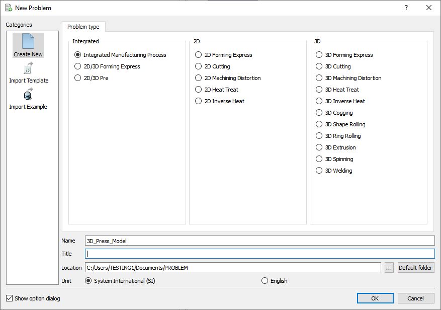
Problem type selection window
Multiple operation wizard will open with the New Project dialog as shown in Fig. 3DPML1.2., at this point, user will be prompted to specify a project name (system will create a separate folder with this project name) and title for this session. We will use “3D_Press_Model ” as the project name in this session. 3D Forming operation can also be added in “New Project” dialog (see Fig. 3DPML1.2.), but we will add the 3D Forming operation in this lab from the operations list in the Explorer, so do not check the “First operation” check box in the “New Project” dialogue. Click on ![]() to continue to open the operation.
to continue to open the operation.
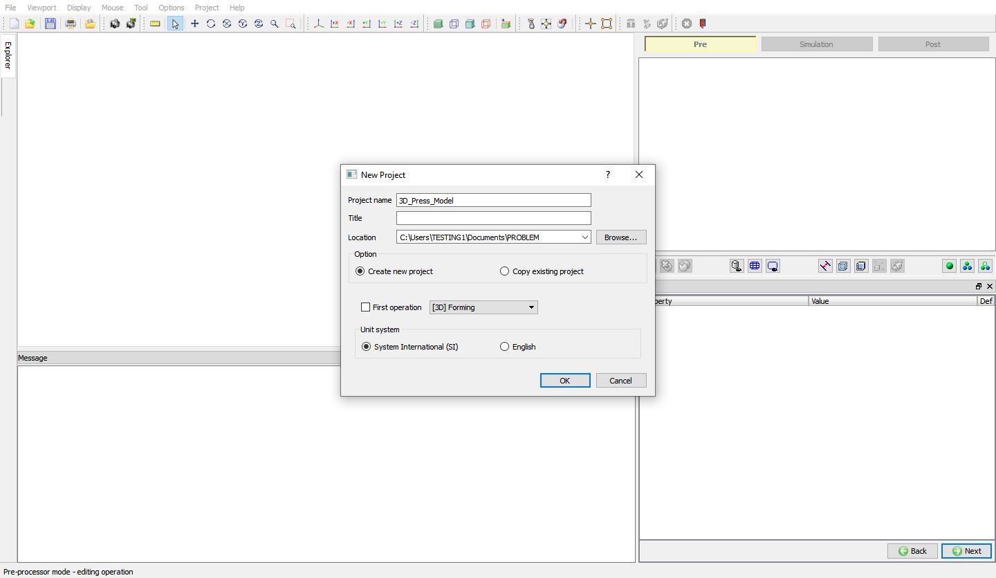
Adding 3D Forming Operation from MO Wizard from new Project window
Adding 3D Forming operation
Add one 3D Forming operation from the Explorer Operations list. Operation can be added by clicking on ![]() button adjacent to 3D Forming in Explorer or user can also add by drag and drop into the Operation Editor (See Fig. 3DPML1.3.). As we add operation, Process page will be opened in the properties area.
button adjacent to 3D Forming in Explorer or user can also add by drag and drop into the Operation Editor (See Fig. 3DPML1.3.). As we add operation, Process page will be opened in the properties area.
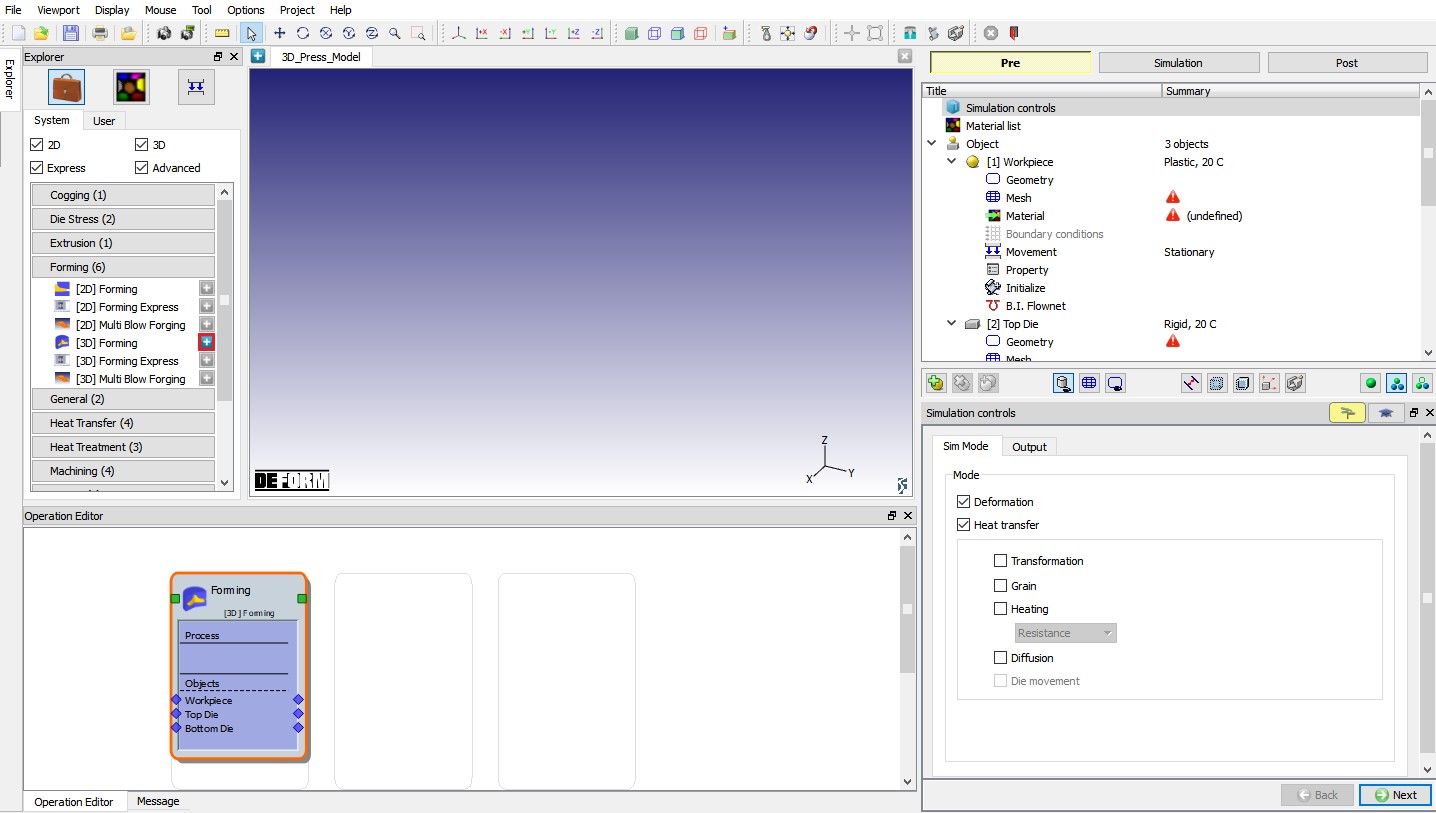
Adding 3D Forming Operation from explorer
Import 3D Connecting Rod example keyfile
Import “3D_ConnectingRod.KEY ” file from DEFORM Installation 3D\3D_Examples\SI\Forging directory using File![]() Import**Keyfile** ”option. Model setup is imported 3D Connecting Rod keyfile is as shown in Fig. 3DPML1.4.
Import**Keyfile** ”option. Model setup is imported 3D Connecting Rod keyfile is as shown in Fig. 3DPML1.4.
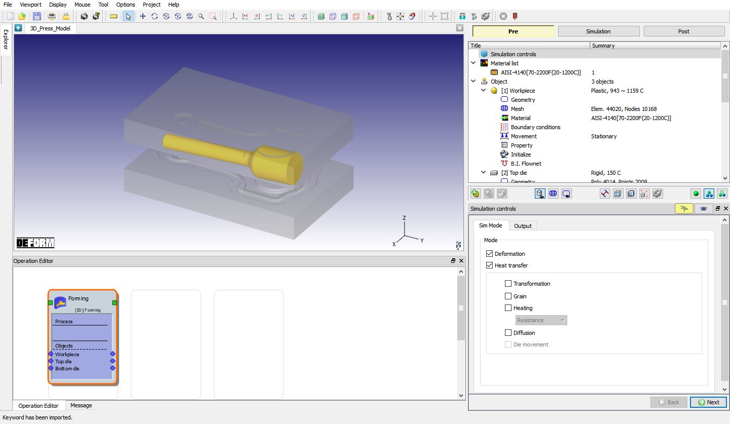
Imported 3D Connecting Rod example
Defining Simulation controls and Press model data
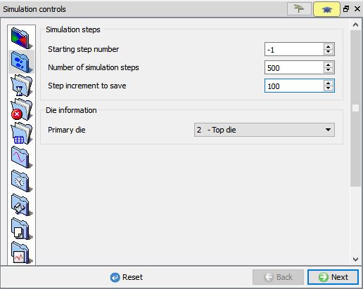
In Simulation controls page, switch to expert mode by clicking on ![]() button. Under Simulation steps
button. Under Simulation steps![]() tab, define Number of steps as 500 and Step increment to save as 100 steps as shown in Fig. 3DPML1.5.
tab, define Number of steps as 500 and Step increment to save as 100 steps as shown in Fig. 3DPML1.5.
Simulation steps page
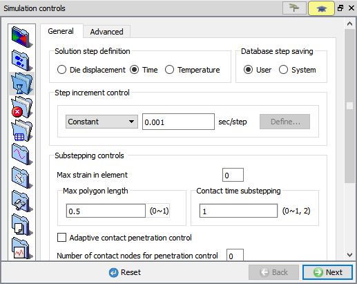
Click on Step increment to Save ![]() tab , select “Time ” radio button as “Solutionstep definition ” and define Step increment control as constant 0.001 sec/step as shown in Fig. 3DPML1.6.
tab , select “Time ” radio button as “Solutionstep definition ” and define Step increment control as constant 0.001 sec/step as shown in Fig. 3DPML1.6.
Step increment controls page
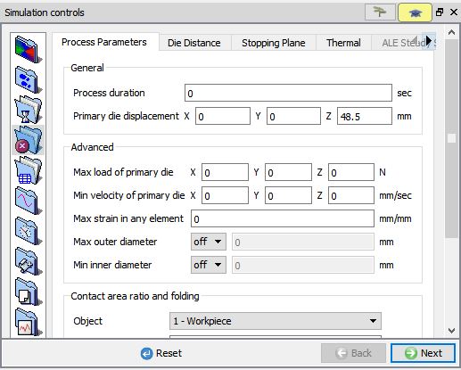
Click on Stopping controls![]() **tab, define **Primary die displacement as “48.5 mm ” as shown in Fig. 3DPML1.7. Click on Die distance tab and click on
**tab, define **Primary die displacement as “48.5 mm ” as shown in Fig. 3DPML1.7. Click on Die distance tab and click on ![]() button to initialize the pre-defined die distance stopping criteria.
button to initialize the pre-defined die distance stopping criteria.
Stopping controls page
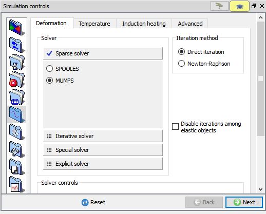
Click on “Solversettings ” ![]() tab, select “MUMPS ” solver under Deformation sub tab as shown in Fig. 3DPML1.8.
tab, select “MUMPS ” solver under Deformation sub tab as shown in Fig. 3DPML1.8.
Note: Sparse solver (MUMPS or SPOOLS) should be used for Press model simulation.
Solver settings – Deformation solver page
Click on Press model![]() , select Press Model “On “ radio button, with default “Pressmodel # 1 ” as Press model name. Define the Reference press center as (93.094 , 152.895 , -40.5) by considering reference point to be on the bottom die bottom surface center as shown in Fig. 3DPML1.9.
, select Press Model “On “ radio button, with default “Pressmodel # 1 ” as Press model name. Define the Reference press center as (93.094 , 152.895 , -40.5) by considering reference point to be on the bottom die bottom surface center as shown in Fig. 3DPML1.9.
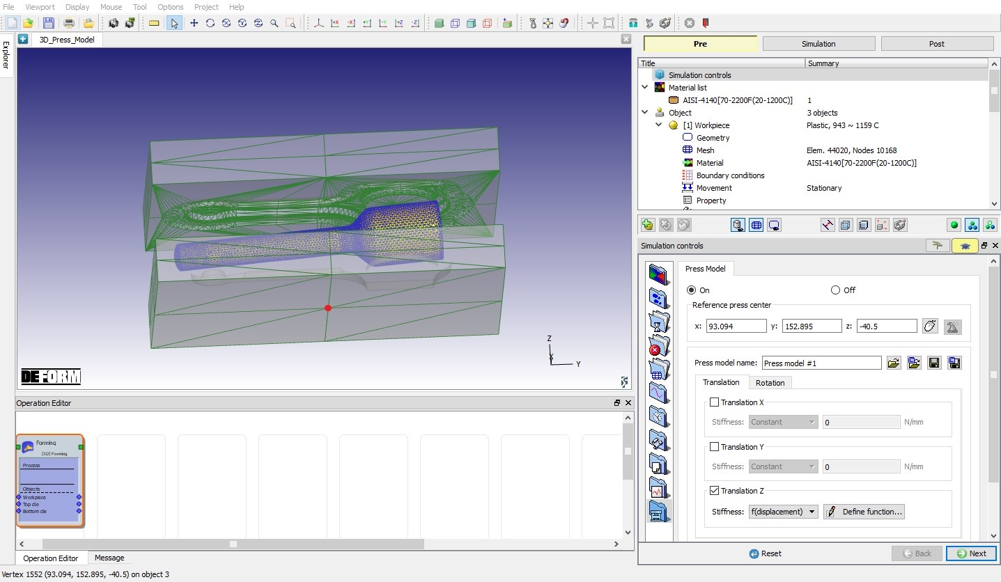
Press Model page
Under Translation tab, check the “TranslationZ” check box, then select Stiffness as “f(displacement) ” and click on ![]() button. In function window, enter the below data as shown in table as shown in Fig. 3DPML1.10.
button. In function window, enter the below data as shown in table as shown in Fig. 3DPML1.10.
| Displacement | Force |
|---|---|
| 0 | 0 |
| 0.5 | 10000 |
| 1.5 | 5140000 |
| 2.5 | 10280000 |
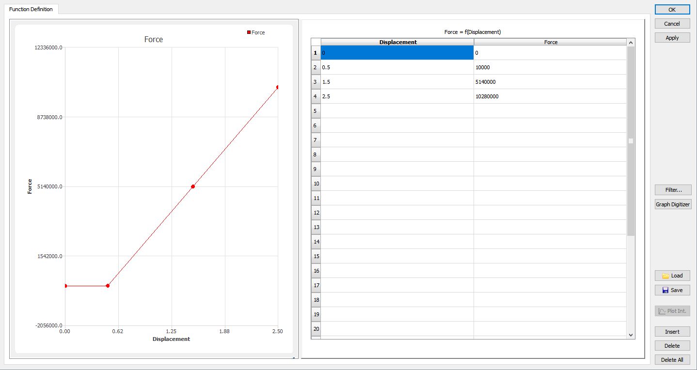
Translation Z – Stiffness Function of Displacement function window
Under Rotation tab, check the “RotationX” check box, then select Stiffness as “f(angle) ” and click on ![]() button. In function window, enter the below data as shown in below table as shown in Fig. 3DPML1.11.
button. In function window, enter the below data as shown in below table as shown in Fig. 3DPML1.11.
| Angle | Torque |
|---|---|
| 0 | 0 |
| 0.001 | 10000000 |
| 0.002 | 442000000 |
| 0.004 | 1326000000 |
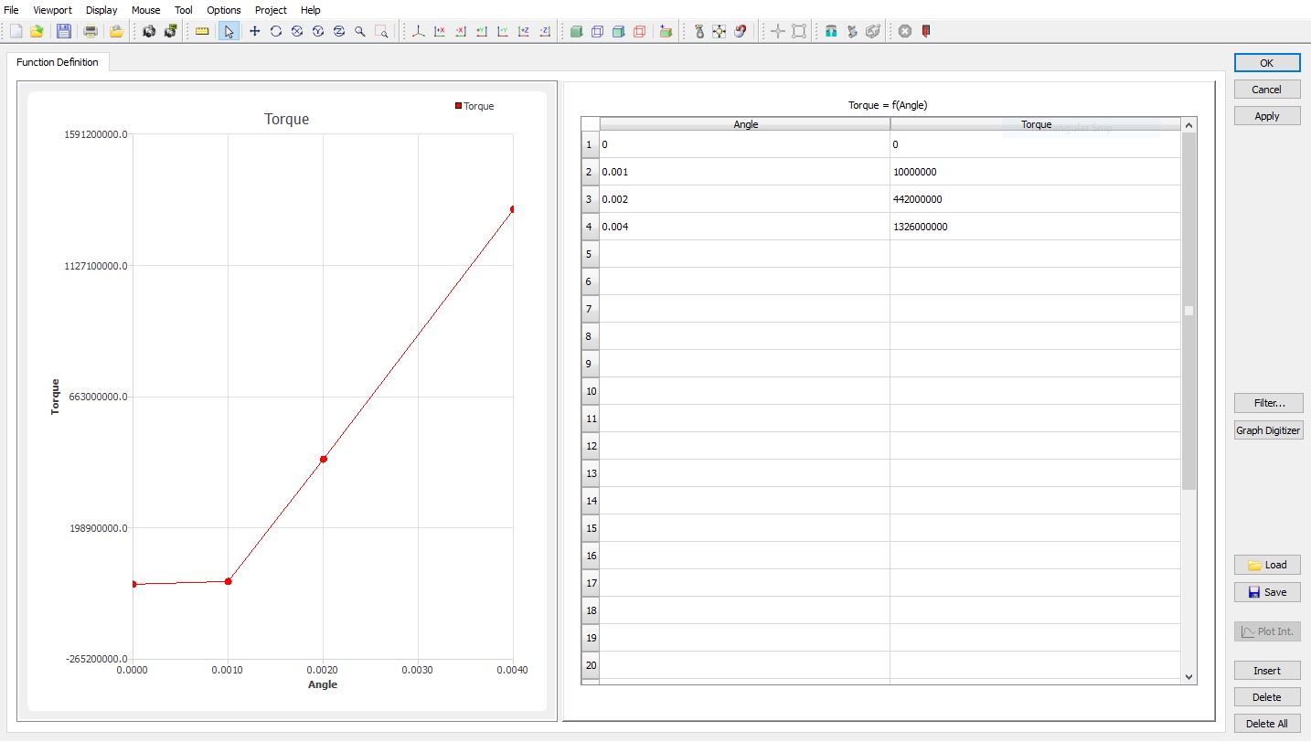
Rotation X – Stiffness Function of Angle function window
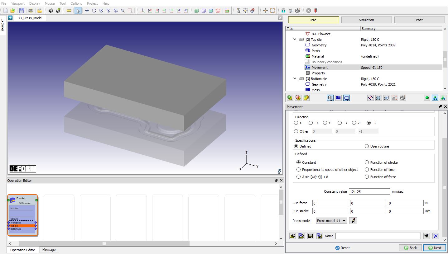
Assign Top die movement
In operation tree, click onTop die Movement , modify the Top die movement to 121.25 mm /sec and under Press model pull down menu select “Pressmodel # 1 ” as shown in Fig. 3DPML1.12. Press model displacement window can be opened by clicking on ![]() button, in this lab we are not defining initial displacement and Rotation value as shown in Fig. 3DPML1.13. So, click on
button, in this lab we are not defining initial displacement and Rotation value as shown in Fig. 3DPML1.13. So, click on ![]() button with default “0” values. After completion of simulation, at the last we can observe the press displacement data in “Press displacement” window. Then click on
button with default “0” values. After completion of simulation, at the last we can observe the press displacement data in “Press displacement” window. Then click on ![]() button until DB Generation page.
button until DB Generation page.
Top Die Movement page
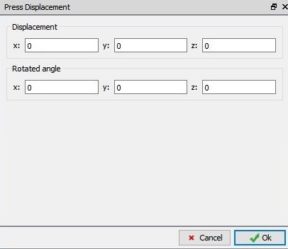
Press model displacement window
Generating Database
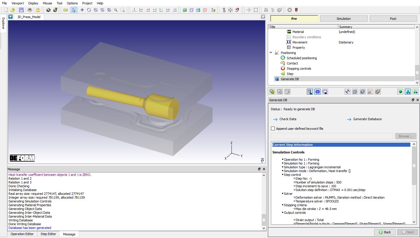
In operation tree, select “Generate DB ”, then click on ![]() button to have the program check to see if anything was missed in the problem setup. During the checking process, messages in the red colour signify data that needs to be fixed before a simulation can be run (such as when you forget to define any material data).
button to have the program check to see if anything was missed in the problem setup. During the checking process, messages in the red colour signify data that needs to be fixed before a simulation can be run (such as when you forget to define any material data).
Click on ![]() button to generate the database as shown in Fig. 3DPML1.14.
button to generate the database as shown in Fig. 3DPML1.14.
Generating Database
Running simulation
Once the database has been generated switch to the Simulation mode by clicking on ![]() button above the operation tree. Click on the
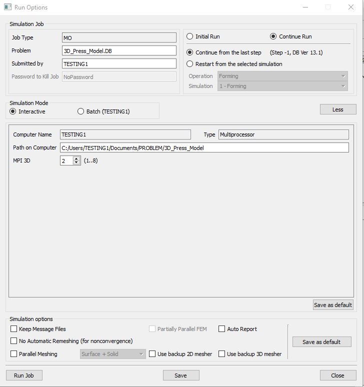
button above the operation tree. Click on the ![]() action label to open the Run Options dialog as shown in Fig. 3DPML1.15. Use the default ContinueRun option to select “Continuefrom the last step ” (from step -1) option and then select the Simulation mode as Interactive radio button.
action label to open the Run Options dialog as shown in Fig. 3DPML1.15. Use the default ContinueRun option to select “Continuefrom the last step ” (from step -1) option and then select the Simulation mode as Interactive radio button.
To define MPI settings, click on ![]() button, then define “MPI3D ” as 2 (or any number depending on your 3D MPI license) as shown in Fig. 3DPML1.15. and then click on
button, then define “MPI3D ” as 2 (or any number depending on your 3D MPI license) as shown in Fig. 3DPML1.15. and then click on ![]() button to run the simulation.
button to run the simulation.
Run Options Popup
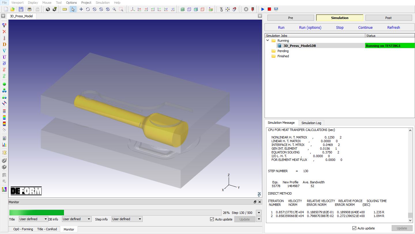
The progress of the simulation can be monitored as it is running by looking at the Simulation Message tab and Simulation Graphics from the Graphics display region in Simulation mode. If ![]() option is checked in Simulation Message tab, which is the default setting, the Message file will refresh automatically.
option is checked in Simulation Message tab, which is the default setting, the Message file will refresh automatically.
The Message file provides information about which simulation step the simulation is currently on and information dealing with how well the simulation is running as shown in Fig. 3DPML1.16.
Simulation mode
Post Processing
After the simulation has completed, click on ![]() tab, MO post processor will open. Play the animation and observe the die movement (see Fig. 3DPML1.17.).
tab, MO post processor will open. Play the animation and observe the die movement (see Fig. 3DPML1.17.).
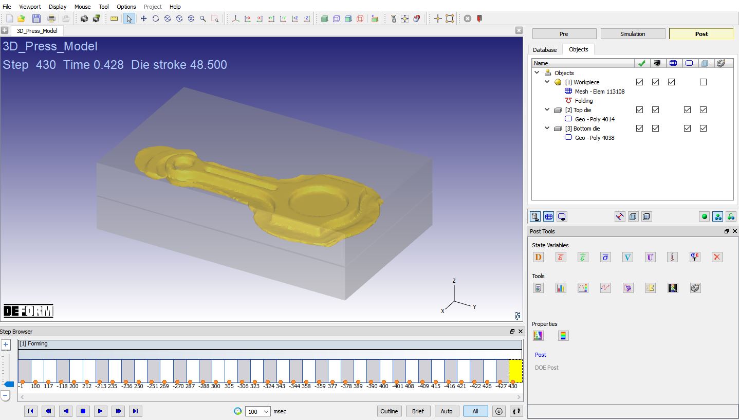
MO Post mode after simulation is completed
We can plot Press model output using Load stroke Graph and using Summary Deformation State variable output.
Click on Graph![]() , select Top die and plot press force-z /press torque -x to see the press loading history. Plotted Press forceZ and Press torque X is as shown in Fig. 3DPML1.18. and Fig. 3DPML1.19.
, select Top die and plot press force-z /press torque -x to see the press loading history. Plotted Press forceZ and Press torque X is as shown in Fig. 3DPML1.18. and Fig. 3DPML1.19.
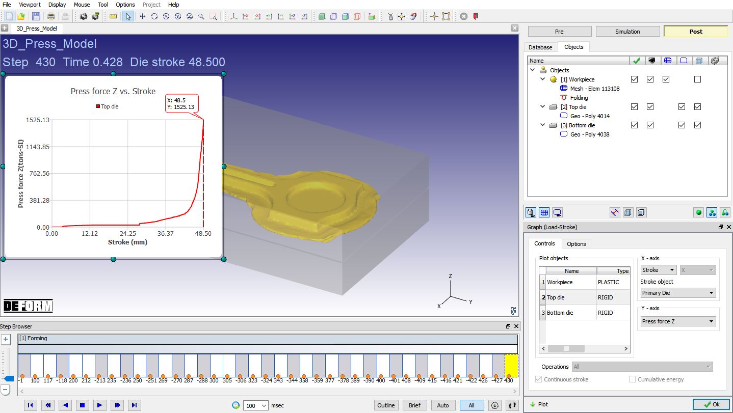
Load stroke - Stroke v/s Press force Z plot
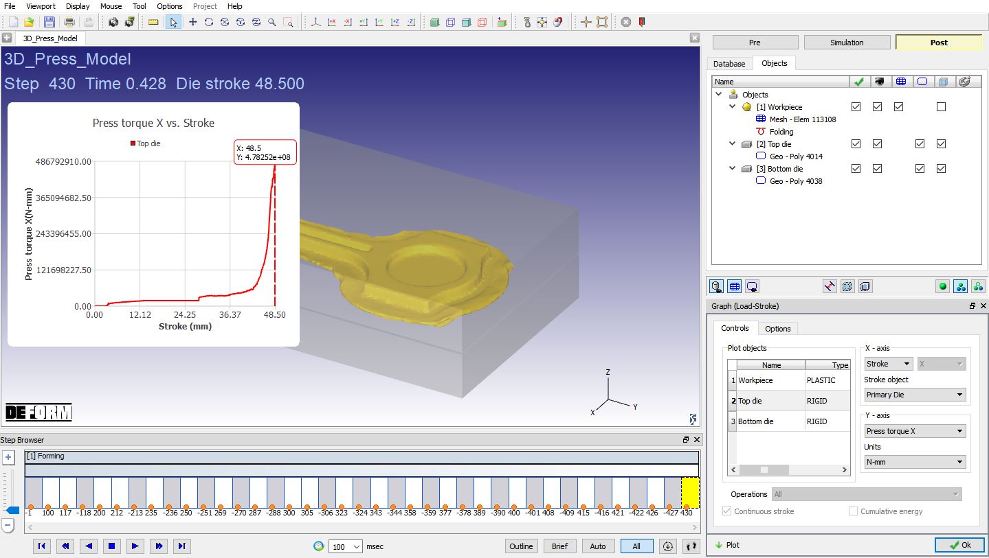
Load stroke - Stroke v/s Press torque X plot
Plot Press displacement -Z / Press rotated angle -x curves to see the press deformation history. Plotted Press displacementZ and Press rotated angle X is as shown in Fig. 3DPML1.20. and Fig. 3DPML1.21.
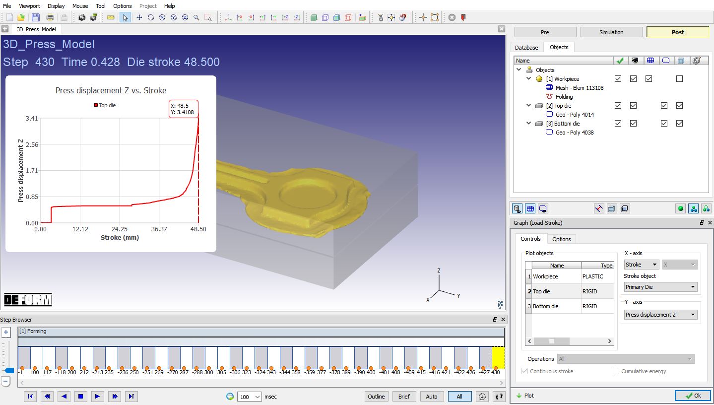
Load stroke – Stroke v/s Press displacement Z plot
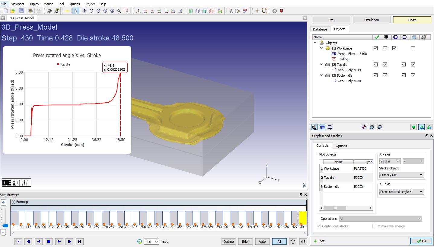
Load stroke – Stroke v/s Press rotated angle X
Plot Press speed curves plot as shown in Fig. 3DPML1.22.
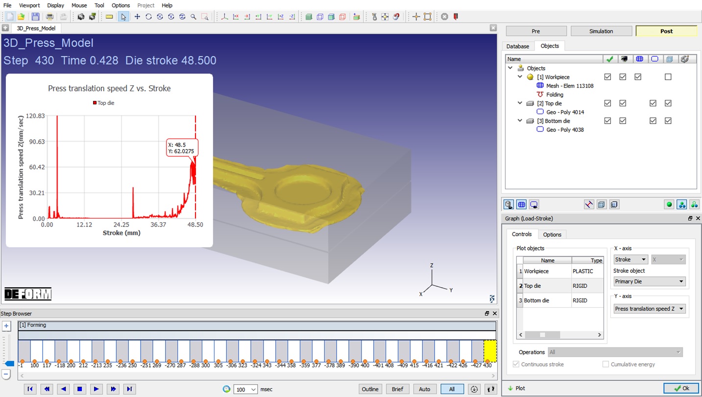
Load stroke – Stroke v/s Press translation speed Z