18.1. Boolean Operation
18.1.1. Boolean operation for 2D object
18.1.2. Boolean operation for 3D object
What to do after Boolean operation
[2D, 3D] This capability allows the user to subtract volume from the mesh of an object from the geometry of another object or Boolean with respect to a plane (option available only for 3D) or Slice layers (option available only for 3D)
Definitions:
Meshed object: An object with a solid mesh giving the object a volume definition.
Geometry object: An object with a surface definition only.
Note that some objects can have both definitions such as a rigid object with thermal calculations turned on. The geometry is used for deformation calculations and the mesh is used for thermal calculations. In the case of a plastic, elastic, porous or elasto-plastic object, the geometry is only used for meshing purposes and is not used for simulation calculations.
The Boolean operation dialog is available on Top Tool bar and the object to be subtracted from should be selected and the Boolean ![]() button should be selected.
button should be selected.
Boolean operation for 2D object
There is only one way to perform this Boolean calculation fro 2D:
Boolean with respect to another object : the user should pick the object to be subtracted. After this please click ![]() (See Fig. 18.1.1.). In below See Fig. 18.1.2. showing boolean the workpiece with respect to Top object.
(See Fig. 18.1.1.). In below See Fig. 18.1.2. showing boolean the workpiece with respect to Top object.

Boolean Workpiece from Top die (Before Boolean)

Boolean Workpiece from Top die (After Boolean)
Note:
In some rare cases where the Boolean definition corresponds exactly to the node locations, some nodes can cross the Boolean plane you have defined. In this case, slightly tweaking the position of the plane will solve this (as little as 1e-6 inches or mm).
Boolean operation for 3D object
To boolean 3D object we have three options:
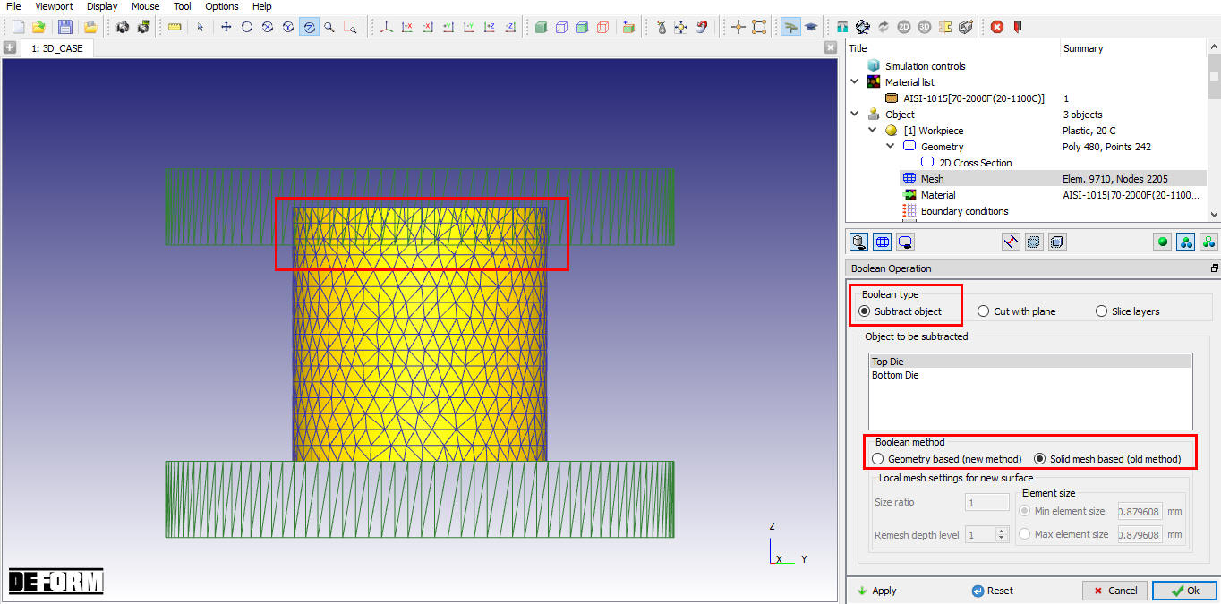
- Subtract object : using this user should pick the object to be subtracted from the current selected object. After selecting the object user can click
 button.
We have two type of Boolean method in subtract object option:
- Geometry based (new method) : Using Geometry based option if we do Boolean operation, it will Perform Boolean and then Local Remeshing as per the defined input( See Fig. 18.1.3.). This will generate smooth mesh as shown in Fig. 18.1.5.

3D Object Geometry based (new method) Boolean operation
- Solid mesh based (old method) : Using Solid mesh based if we do Boolean operation (See Fig. 18.1.4.), it will perform boolean and then generate only Solid mesh, please refer Fig. 18.1.5.
3D operation Solid mesh based (old method) Boolean operation
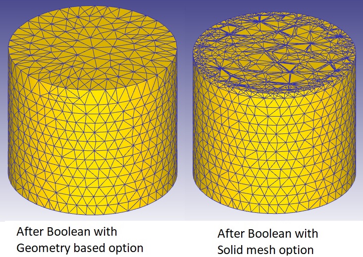
Generate Mesh after boolean operation with different Subtract object type option
- Cut with plane : User can also boolean object by defining just plane even if object is not available using this option, user should pick the Plane and then define a point and a normal to the Boolean plane (see Fig. 18.1.6.). After this click on . (See Fig. 18.1.7.)
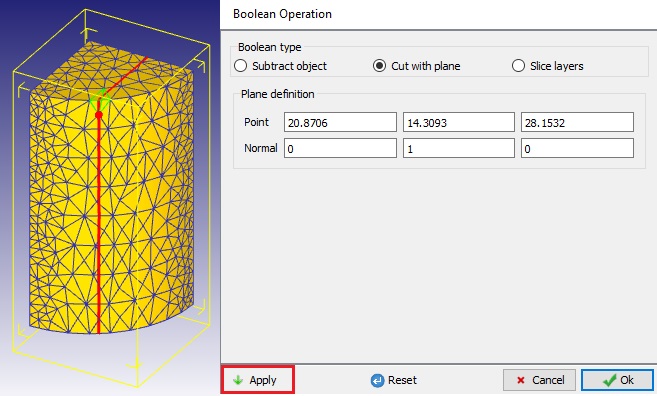
3D Object Cut with plane Boolean operation (Before Boolean)
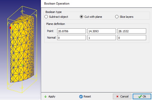
3D Object Cut with plane Boolean operation (After Boolean)
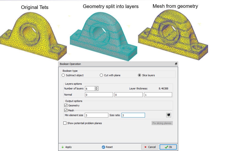
- Slice layers: Using Slice layers option we can do multiple slices of an object and after slicing the objects we can generate new mesh for each sliced layer by defining Mesh settings in Output options. This option is useful for additive manufacturing simulations and for objects having multiple materials similar to multi layer composites. Following example demonstrates the slicing of bearing into 6 layers.(See Fig. 18.1.8.)

Slice layers page
We are slicing simple Bearing block into 6 layers using Slicing layers option.
- After generating Tet Mesh for Bearing block, open Boolean option and select Slice layers. Define Number of layers as 6 and with mesh data click on button. See Fig. 18.1.9.
Sliced Bearing block using Slice layers option
- Now go back to Geometry page, select Examine and observe the Number of Surfaces of Bearing Block. (See Fig. 18.1.10.)

Examine Window
What to do after Boolean operation?
The cut planes will show a poorly structured mesh. This is because many elements were cut. To improve the mesh quality perform the following actions (From DEFORM V12, Geometry based method can be used to generate smoother mesh ):
-
Press
 when the Boolean operation is satisfactory.
 -
Go to Geometry
-
Extract the mesh (The purpose is to prevent any geometry definition from being used for the meshing)
-
Go to mesh and mesh the object (Do not perform a manual remesh)
-
Go to Data Interpolation to restore the state variables.
After this, you should have successfully updated your part with the desired volume removed.
Related Topics: