Appendix XIV Rotating Workpiece Simulations
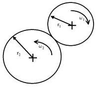
In this, special techniques for spinning workpiece simulations are discussed. Among the applications that this would cover would be cross-rolling simulations. (See Fig. AXIV.1.)
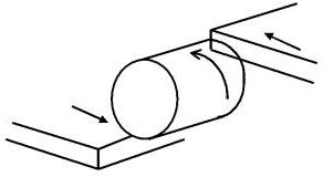
Cross-rolling diagram
In the above case, there is a problem when the workpiece rotates. The problem occurs due to the nature of updating nodal position based on integrating velocity over a time increment. The simple process of updating based on instantaneous velocity over a discrete time interval can cause an increase of the diameter of the workpiece. As seen in Fig. AXIV.2. all the nodal velocities are perpendicular to the radius where they are located. Thus, simply updating the coordinates based directly on their velocity will incur an increase in radius and in volume as well.
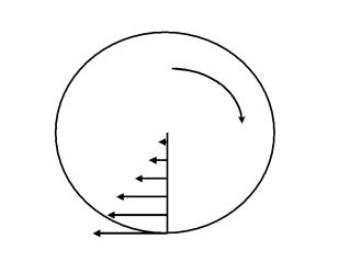
Velocity profile of a rotating body
Another issue that may arise in simulations where the workpiece is turning based on friction at very localized regions of the surface (particularly thread-rolling cases). The workpiece may tend to slide rather than be rotated. This arises due to sparse contact that can occur between the tool and the workpiece. The sparse contact arises when the workpiece has a coarse mesh definition or when the tool geometry is coarsely defined.
Currently, there exists a number of different solutions for handling these types of problems. These solutions are listed below.
Moving tools about a non-spinning workpiece
Motivation: Although in the reality the workpiece rotates during deformation, it may be advantageous to not allow the workpiece to rotate and let the tools move about it. This will not change the nature of deformation, but has the following advantages:
-
Since the workpiece does not spin, the increase in volume is avoided and
-
Flow-net can be used in post-processing.
Cartesian coordinates vs. cylindrical coordinates : For most of the cases, it is straightforward to specify the orbiting movement in the Cartesian coordinate system for a rotating tool, which orbits like a planetary gear. The user has to define the first and second rotations. However, when there is a tool translation that is not parallel to the second rotational axis, it is convenient to use a cylindrical coordinate system for the tool. We will only elaborate the latter case in this section.
Examples:
-
Spinning with a roller, if the user wants to fix the workpiece and to rotate the roller (See Fig. AXIV.3.), and
-
Thread rolling between two flat dies, if the user wants to fix the workpiece and to rotate the two flat dies (See Fig. AXIV.1.).
How to Implement: If the following conditions are all met, DEFORM-3D will adopt the cylindrical coordinate for that object:
-
The first rotational axis and the second rotational axis are defined and they are apart from each other.
-
The translational movement is non-zero in the direction non-parallel to the second rotational axis.
Description of rotational axis definitions and angle definitions (derived from angular velocity values) for this case
These values are defined in the Rotational Movement window. As seen in Fig. AXIV.3., the first axis is the axis of the rotating tool and the second axis superimposes with the axis for the non-rotating workpiece. The first rotational axis defines the rotational properties of the tool about it’s own axis. If the tool does not spin about its own axis, as in a cross-rolling simulation, the axis center should be specified far from the workpiece axis. The second rotational axis defines the rotational properties of tool about the axis of the workpiece.
As a note:
-
The initial position of this object is always used as a reference. The “Current Angle” in the Rotational Movement window should be zero at Step –1 and will be updated by the system at the end of every step or sub-step. The user should not change its value in a later step in the pre-processor without changing the position of this object accordingly.
-
The direction of the translational movement of this object is defined with respect to this reference position only. It will not be changed in a later step even the object rotates about the second rotational axis. The stroke will be updated in the same way.
In the case of two rotational axes, when the axes are parallel, the angular velocities are defined as follows (Seen Fig. AXIV.4.):
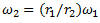
Two rotating bodies with parallel axes
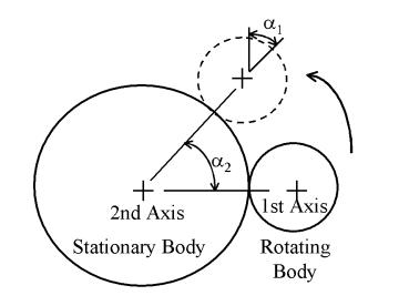
Otherwise, when the axes are at an angle to each other, such as in the case of orbital forming, the angular velocities are defined as, (Seen Fig. AXIV.5.)
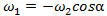
A rotating body with two non-parallel axes
Spinning Workpiece
There are some features used to model the deformation of a rotating workpiece with DEFORM-3D. They are under testing and have yet been officially added to DEFORM-3D. However, the user may activate these features when necessary by defining a data file “AXIS.DAT” in the working directory of a simulation. The options and contents of AXIS.DAT are explained as follows. This functionality works for a single rigid-plastic object and rigid tools only.
Here is the outline of AXIS.DAT file structure as described on a line-by-line basis. Each line is data that define how this feature will work for the current simulation. Once this file is created and placed in the current directory that is running a simulation, it will be read by DEFORM and applied to the simulation.
Caution:
When finished using this file in a simulation, be careful to not run another simulation that does not require it as DEFORM will use this and may cause an errant simulation. Either rename or delete the file before running another simulation in the same directory.
There are two functionalities that are available in this feature: Coordinate updating based on rotational motion and enforced rotational motion of the workpiece. These two features (modes) can be enabled either separately or simultaneously depending on the mode set in the AXIS.DAT file. The rest of the data defines certain options on how these modes apply to the current case. Here is a line by-by-line description of the file.
Line 1: KOBJAX - Object number (an integer)
Line 2: Mode – An integer value that determines which function this feature should use.
Line 3: RAXIS(1),RAXIS(2),RAXIS(3) (3 real numbers)
Direction vector parallel to the axis of rotation. These components are unit less.
Line 4: ORGN(1),ORGN(2),ORGN(3) (3 real numbers)
A point that lies on the axis of rotation. This point can be any point on the central axis. The units for each component is mm for SI simulations and inches for the English unit system.
Line 5: RADCTR,OMECTR (2 real numbers)
RADCTR is the radius of a specified central core about the rotational axis for which rotational speed is fixed to the rotational speed of OMECTR. The units of RADCTR is mm for SI simulations and inches for the english unit system. The units of OMECTR is rad/s for SI and the English unit system.
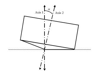
Line 6: XMIN, XMAX (2 real numbers; optional)
RADCTR, XMIN and XMAX define the dimensions of a cylinder within which the nodes of object KOBJAX are forced to rotate about RAXIS at a rotational velocity OMECTR. (See Figure D.3).
Line 7: XMIN2, XMAX2 (2 real numbers; optional)
XMIN2 and XMAX2, if available, define a second cylinder with an infinite radius within which the nodes of object KOBJAX are forced to rotate about RAXIS, but the magnitude of the nodal velocity is the result of simulation.
Notes on Line 2
Mode = 1 Enforces rotational update of nodal coordinates (This solves the problem described
above with the volume increase).
Mode = 3 Part of object KOBJAX (defined below) is forced to spin
about an axis (defined by RAXIS) in addition to enforcement of rotational updating.
Mode = 5 Part of object KOBJAX (defined below) is forced to spin
about an axis (defined by RAXIS) in addition to enforcement of rotational updating, but the
consolidation technique is applied.
Notes on Line 5
If OMECTR = 0, the nodal updating direction is specified as rotational, while the magnitude of each node velocity is the result of simulation (i.e. rigid tool(s) will control the speed of the nodes).
If OMECTR != 0, XMIN and XMAX (discussed below) are defined as the minimum and maximum bounds with respect to the axis and the origin defined on Lines 2 and 3. So are XMIN2 and XMAX2, if any. ( Fig. AXIV.6.)
Outline of dimensions for central core
Notes on Line 6
XMIN and XMAX, if available,are the axial bounds of the central core with the respect to ORGN.
If Line 6 is not defined, the cylinder has an unlimited length and Line 7 is not needed.
(Lines 5,6 and 7 are used only if Mode 3 is selected)
Option = 5 allows for the user to specify two independent cores that can drive spinning.
Only new inputs are explained.
Line 1: KOBJAX - Object number (an integer)
Line 2: Option (an integer)
Option = 5 Part of object KOBJAX (defined below) is forced to spin
about an axis (defined by RAXIS) PLUS Option 1, but the
consolidation techinique is applied.
Line 3: RAXIS(1),RAXIS(2),RAXIS(3) (3 real numbers)
Direction vector defining the axis of rotation.
Line 4: ORGN(1),ORGN(2),ORGN(3) (3 real numbers)
Origin of the above axis.
Line 5: NUMSEC,ISECPL (2 integers)
NUMSEC = 1 or 2 – How many rigid zones to be specified
ISECPL = 0: if NUMSEC = 1, nothing is implied
NUMSEC = 2, two zones are not coupled
ISECPL = 1: if NUMSEC = 2, two zones are coupled
INPUT FOR SECTION 1:
Line 6: RADCTR, OMECTR (2 real numbers)
PLEASE NOTE: The meaning of OMECTR is different than that in
Option 3:
If OMECTR is set to 1.e+12, the rotating direction is specified,
while the magnitude of each nodal velocity is the result of
simulation.
If OMECTR is set to 0, the part of workpiece is fixed.
Line 7: XMIN, XMAX , VXMIN, VXMAX (4 real numbers; optional)
VXMIN is the speed of the left bounding point, XMIN
VXMAX is the speed of the right bounding point, XMAX
INPUT FOR SECTION 2, IF NUMSEC=2:
Line 6: RADCTR, OMECTR (2 real numbers)
PLEASE NOTE: The meaning of OMECTR is different than that in
Option 3:
If OMECTR is set to 1.e+12, the rotating direction is specified,
while the magnitude of each nodal velocity is the result of
simulation.
If OMECTR is set to 0, the part of workpiece is fixed.
Line 7: XMIN, XMAX , VXMIN, VXMAX (4 real numbers; optional)
VXMIN is the speed of the left bounding point, XMIN
VXMAX is the speed of the right bounding point, XMAX
Note:
When using a core region, the user should be cautious not to regard the stress or strain within the core region as significant. This core region should be far from the deformation area and in the case of simulations where there is interest in the material at the central region of the spinning object, this method cannot be used. Also, in order for the AXIS.DAT file to work properly in DEFORM-3D, a file named DEF_RSE.DAT containing a single 0 should also exist in the working directory.
Related Topics: