3D Die stress study Lab 2
2.1. Introduction
2.2. Opening project file
2.3. Add Die Stress Study
2.4. Adding Objects
2.5. Top Die
2.6. Bottom Die
2.7. Upper Support
2.8. Lower Support
2.9. Define Inter-Object Relation
2.10. Simulation Controls
2.11. Generate Database
2.12. Post Processing
Introduction
The objective of this lab is to run a die stress analysis. When the stress analysis is being done on only one tool, a one step simulation is sufficient to get accurate stresses. When the stress analysis is being done on die assemblies where there is interaction between the tools, more than one step is typically needed for the die stack to come to a state of equilibrium under the applied load.
In a typical die stress simulation, the workpiece is removed and the forces exerted onto the dies by the workpiece are interpolated onto the tools. In this lab, a shrink fit will also be modeled.
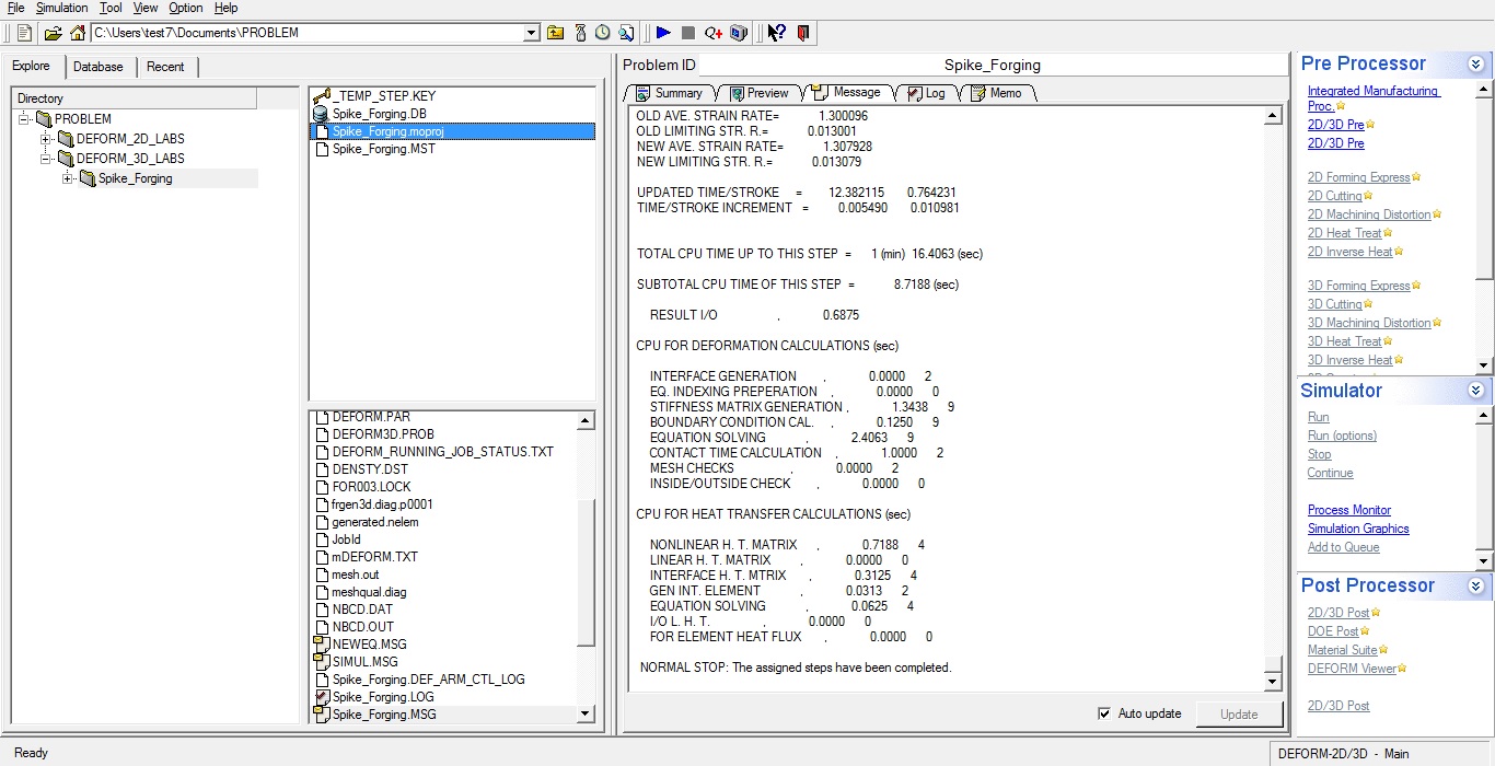
Opening project file
Open Previously simulated Spike_Forging.moproj file in ![]() (DEFORM Integrated Manufacturing Proc.) in Lab03 Spike Forging as shown in Fig. 3DDSL2.1. Integrated Manufacturing Process user interface will open.
(DEFORM Integrated Manufacturing Proc.) in Lab03 Spike Forging as shown in Fig. 3DDSL2.1. Integrated Manufacturing Process user interface will open.
Opening Project file from GUI main
Add Die Stress Study
At top Left corner of the Display window, Left mouse click on ![]() button and select Add Die stress Study operation as shown in Fig. 3DDSL2.2.
button and select Add Die stress Study operation as shown in Fig. 3DDSL2.2.

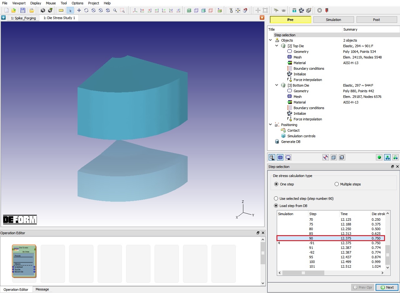
Adding Die stress Study
Die stress operation will add automatically to operation editor under new tab as shown in Fig. 3DDSL2.3. To perform Die stress operation, select step 90 in Step selection page as shown in Fig. 3DDSL2.3. Click ![]() .
.
Adding Die stress Operation From Explorer
Adding Objects
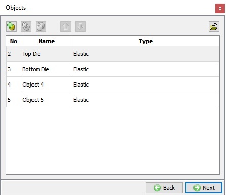
We need two new objects to analyze the effect of shrink fit on Top Die and provide support to Bottom die. By selecting ![]() button, add two objects and name them as Upper support and Lower Support respectively, as shown in Fig. 3DDSL2.4. We will accept the object type as Elastic for all objects. As Top Die is already having mesh, click
button, add two objects and name them as Upper support and Lower Support respectively, as shown in Fig. 3DDSL2.4. We will accept the object type as Elastic for all objects. As Top Die is already having mesh, click ![]() to Top die object page.
to Top die object page.
Adding Objects
Top Die
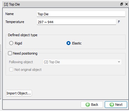
Top die object definition
By default, the object type of rigid objects from the loaded step will be changed to elastic. Keep the object type as elastic for the Top Die object. From v13.1.1, two new options have been introduced in the object page to position the dies in future steps for Multiple steps die stress analysis, we need not use these options for single step die stress analysis hence, keep the Need positioning check box turned off. Click ![]() till Material page.
till Material page.
Top Die object page
Assign Material
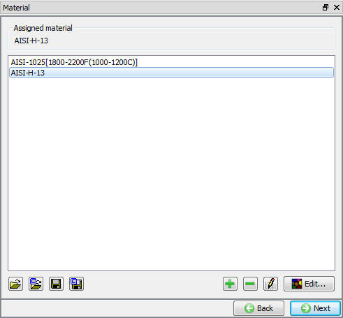
In material window, select AISI-H-13 material as shown in Fig. 3DDSL2.6. and click ![]() .
.
Material Window
Assigning Boundary Conditions
-
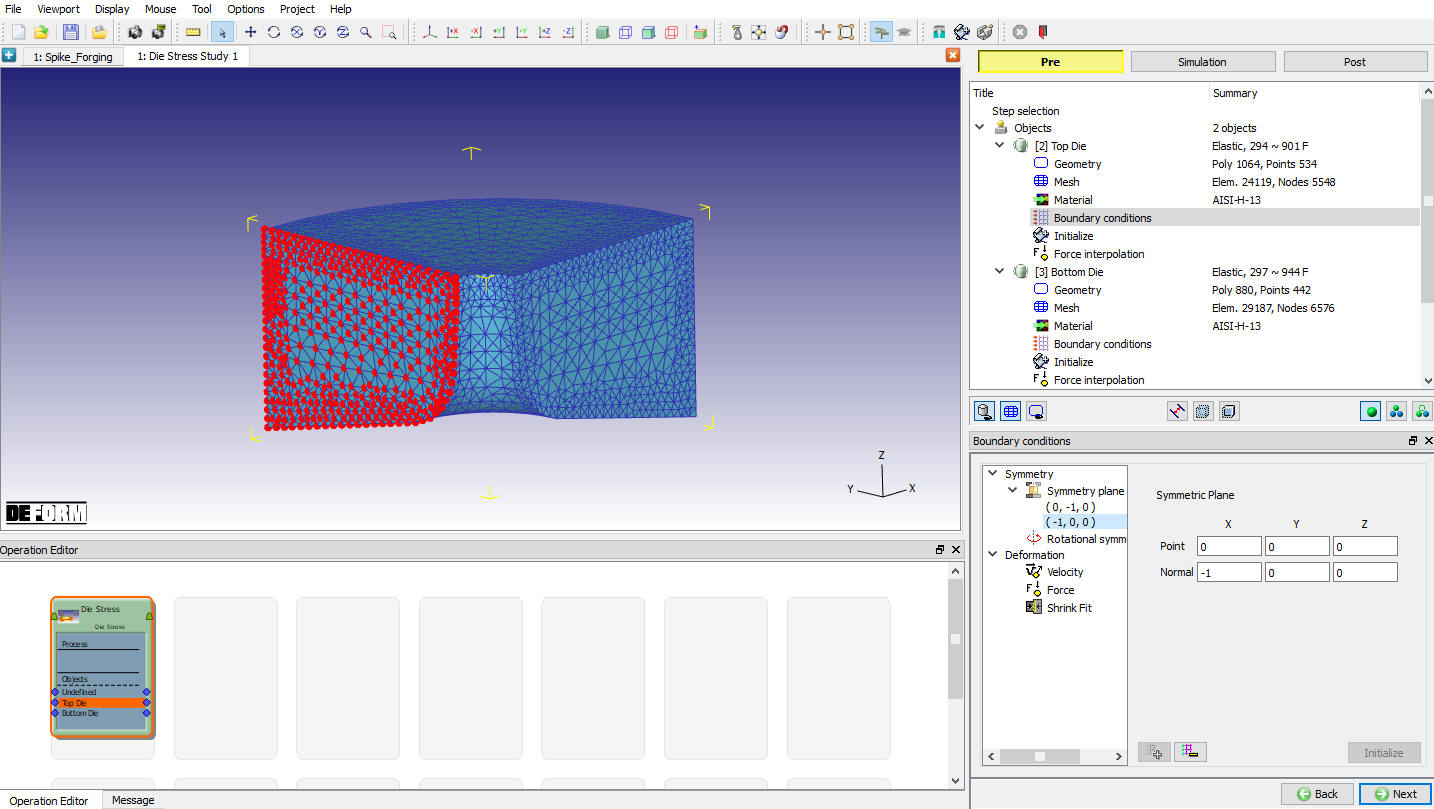
Select the Symmetry plane boundary condition , and then add a boundary condition to each of the Top Die symmetry planes as shown in Fig. 3DDSL2.7.
-
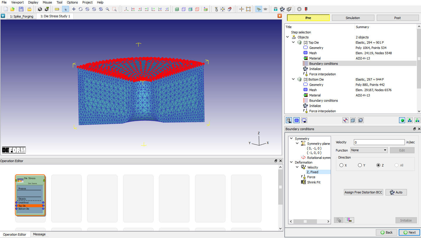
Apply Vz = 0 Velocity boundary condition on the top surface of the Top Die. This boundary condition prevents the die from flying off when the forces are applied. (See Fig. 3DDSL2.8.) Click
 until Force interpolation page.
Assigning Symmetry Boundary conditions
Assigning Velocity BCC
Interpolate Forces for Top die
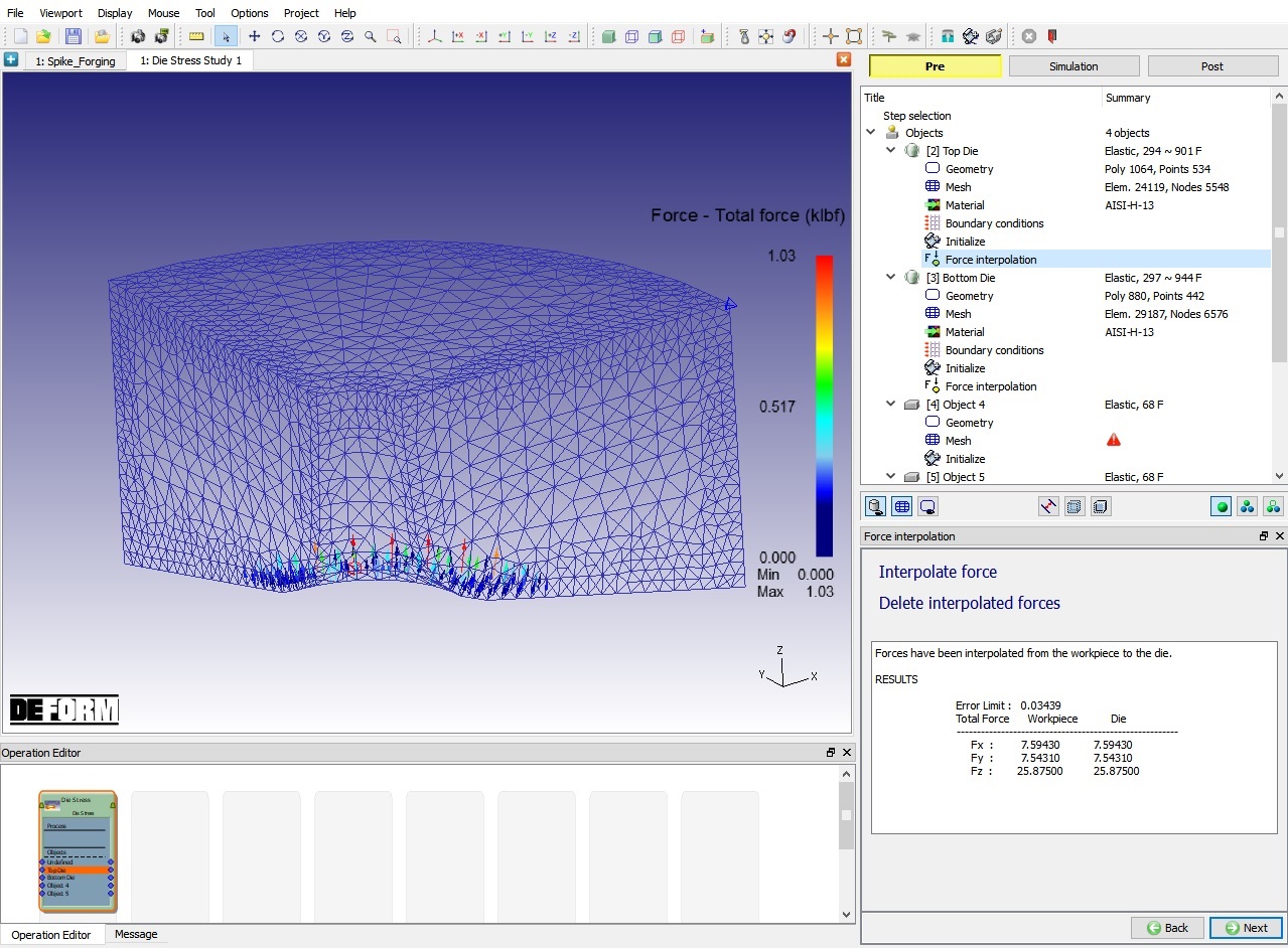
In Force interpolation page, click on ![]() action label as shown in Fig. 3DDSL2.9. Click
action label as shown in Fig. 3DDSL2.9. Click ![]() to Bottom Die page.
to Bottom Die page.
Force Interpolation window
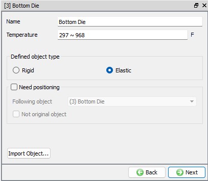
Bottom Die
Bottom die object definition
We will keep the object type as Elastic for the Bottom Die and turn off Need positioning check box.Click ![]() until Material page.
until Material page.
Bottom Die object page
Assign Material
In material window, select AISI-H-13 material as shown in Fig. 3DDSL2.6. and click ![]() .
.
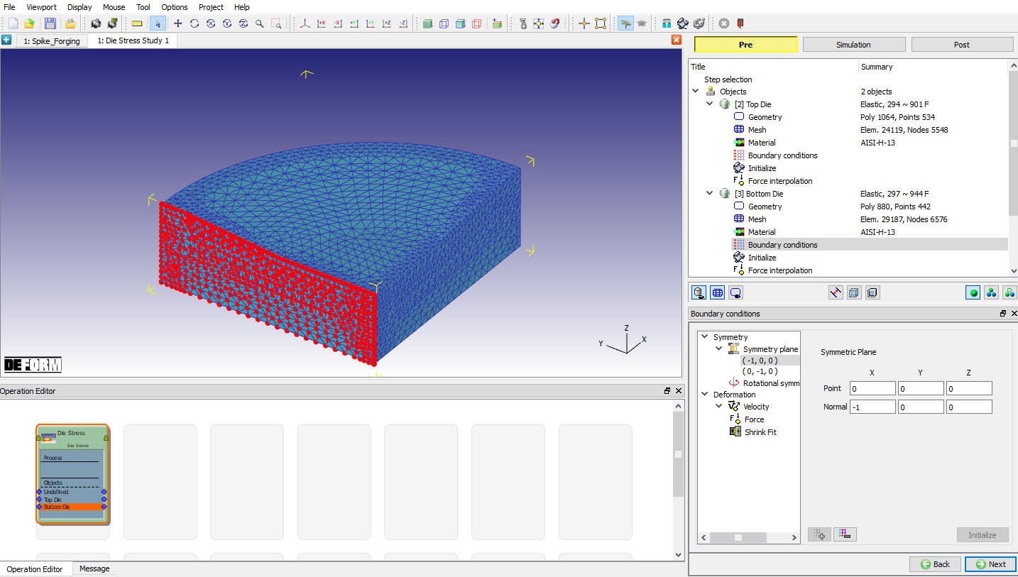
Assigning Boundary Conditions
Select the Symmetry plane boundary condition, and then add a boundary condition to each of the symmetry surfaces as shown in Fig. 3DDSL2.11. We will use Lower support object to prevent Bottom Die from flying off in Z direction. Click ![]() until Force interpolation page.
until Force interpolation page.
BCC Window
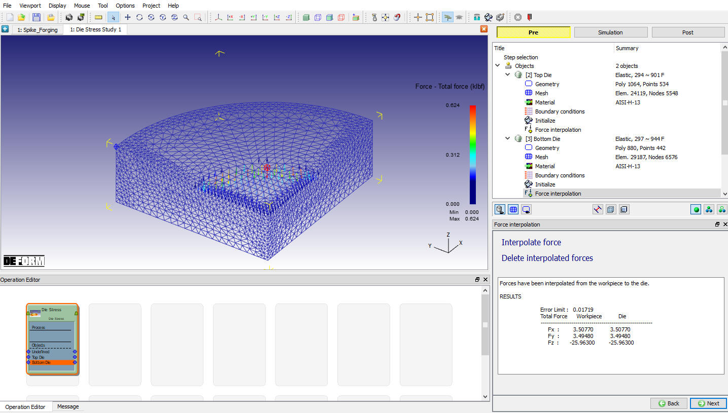
Interpolate Forces for Bottom die
In Force interpolation page, click on ![]() action label as shown in Fig. 3DDSL2.12. Click
action label as shown in Fig. 3DDSL2.12. Click ![]() to Object3 General page.
to Object3 General page.
Force interpolation window
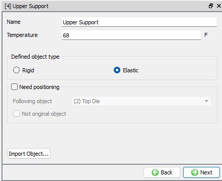
Upper Support
Change the name of Object 3 to Upper Support with Elastic object type as shown in Fig. 3DDSL2.13. and click ![]() .
.
Upper Support Object page
Import Geometry
In Geometry page, click on import geometry from library option (![]() ) and import the UpperSupport.STL file from installation path \SFTC\DEFORM\v_\3d\LABS) . Use
) and import the UpperSupport.STL file from installation path \SFTC\DEFORM\v_\3d\LABS) . Use ![]() button to check the Geometry. Click
button to check the Geometry. Click ![]() to Mesh page.
to Mesh page.
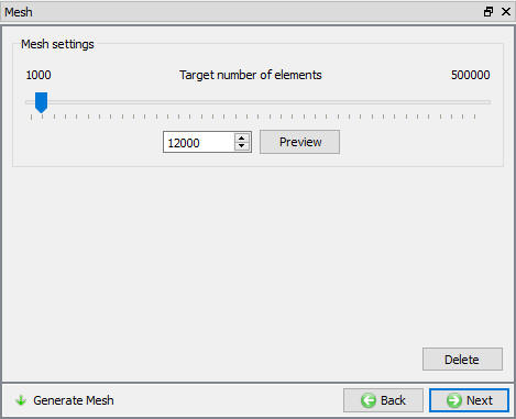
Generate Mesh
Enter Target number of elements as 12000 as shown in Fig. 3DDSL2.14. then click on ![]() . Click on
. Click on ![]() until Material page.
until Material page.
Mesh Generation Window
Assign Material
In material window, select AISI-H-13 material as shown in Fig. 3DDSL2.6. and click on ![]() .
.
Assigning Boundary Conditions
Specify Symmetry plane boundary conditions on the two symmetry surfaces of the Upper Support as shown in Fig. 3DDSL2.15.
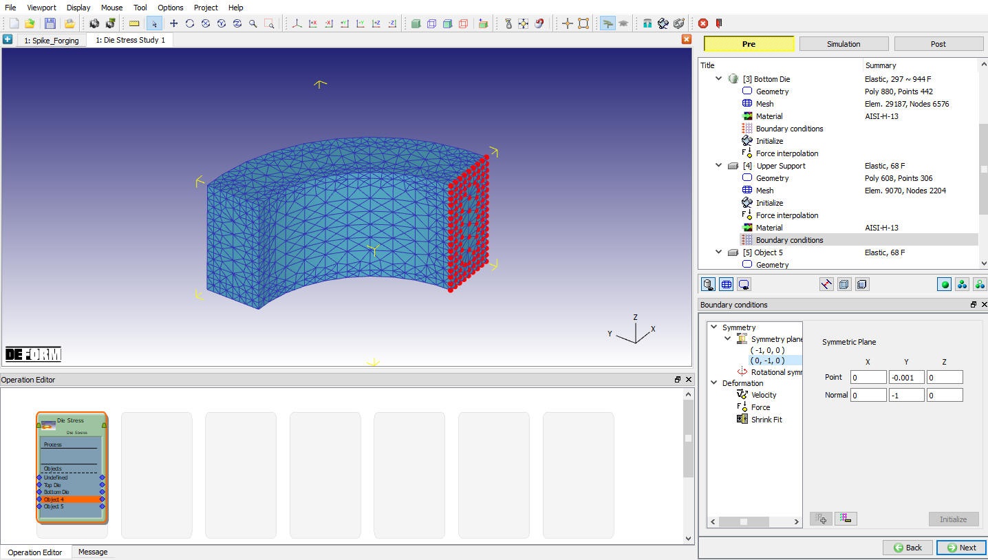
Assigning Symmetry BCC
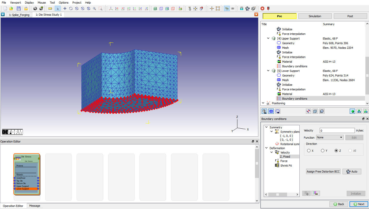
Apply Vz = 0 Velocity boundary condition on the top surface so that the object does not fly off in the Z-direction as shown in Fig. 3DDSL2.16.
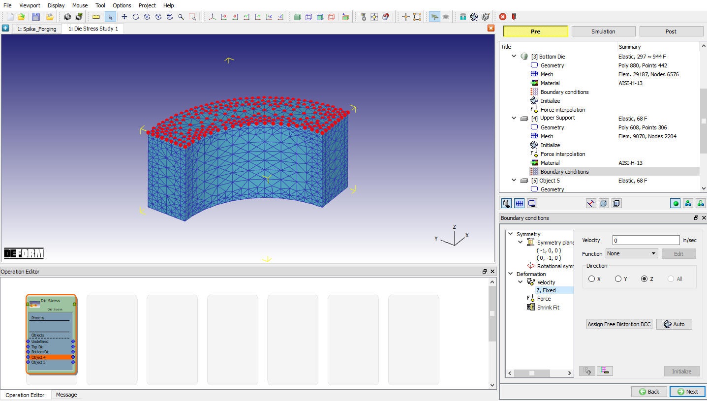
Assigning Velocity BCC
This object also gets a shrink fit applied to it, so select the Shrink Fit boundary condition. Shrink fit is defined radially, so an axis and a point need to be defined. For this analysis, (0, 0, 0) is the point at the center of the dies, and the Z axis is the axis of the objects. If the shrink fit is applied to the inner object, the value should be negative. If the shrink fit is applied to the outer object then the value should be positive. Since we are applying the shrink to the outer object, use a value of 0.004 for the Interference and click on ![]() button. When prompted if you want to move the coordinates of the nodes, click
button. When prompted if you want to move the coordinates of the nodes, click ![]() . (See Fig. 3DDSL2.17.)
. (See Fig. 3DDSL2.17.)
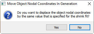
Move object nodal coordinates message
Once the above parameters have been set, Upper support appears as shown in Fig. 3DDSL2.18.
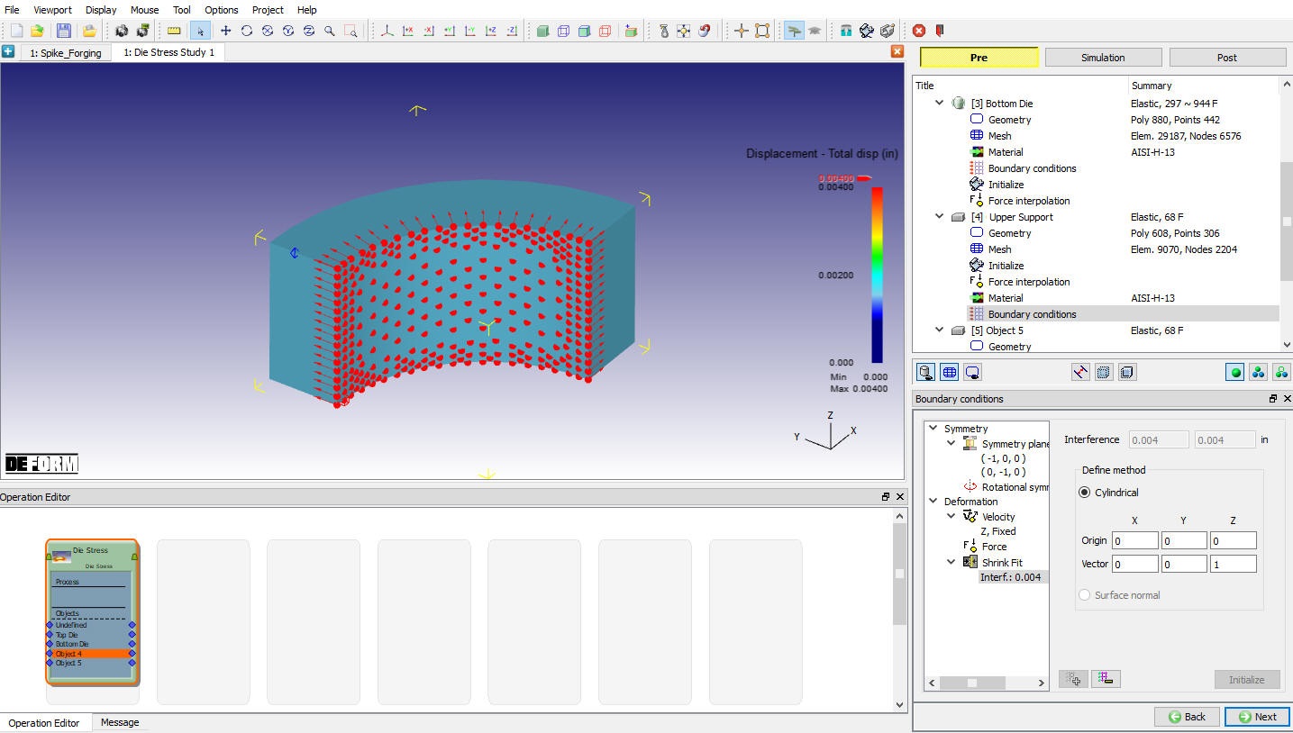
BCC definition Window
For a better look at the applied shrink fit, click on Object Nodes ![]() icon. Plot Displacement variable vector plot using
icon. Plot Displacement variable vector plot using ![]() button to view the applied shrink fit on the Upper Support as shown in Fig. 3DDSL2.19.
button to view the applied shrink fit on the Upper Support as shown in Fig. 3DDSL2.19.
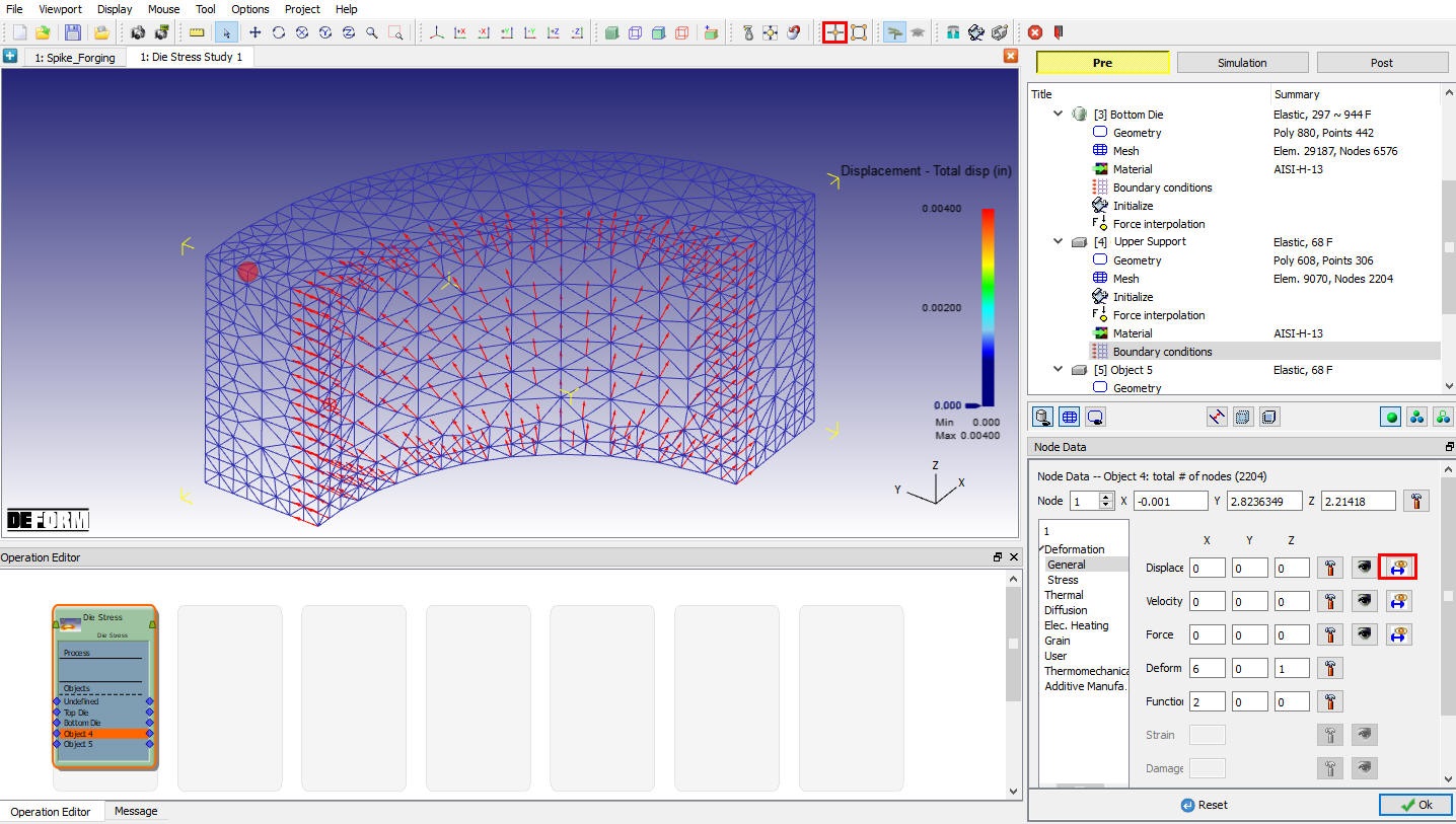
Node Data window
Lower Support
Change the name of Object 4 toLower Support with Elastic object type as shown in Fig. 3DDSL2.20. and click ![]() .
.

Lower support Object page
Import Geometry
In Geometry page, click on import geometry from library option (![]() ) and import the LowerSupport.STL file from installation path \SFTC\DEFORM\v_\3d\LABS). Use
) and import the LowerSupport.STL file from installation path \SFTC\DEFORM\v_\3d\LABS). Use ![]() button to check the Geometry. Click
button to check the Geometry. Click ![]() .
.
Generate Mesh
Enter Target number of Elements as 14000 as shown in Fig. 3DDSL2.21., then click on ![]() button. Click
button. Click ![]() until material page.
until material page.
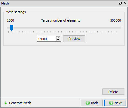
Mesh generation window
Assign Material
In material window, select AISI-H-13 material as shown in Fig. 3DDSL2.6. and click ![]() .
.
Assigning Boundary Conditions
Specify Symmetry plane boundary conditions on the twosymmetrysurfaces of the Lower Support as shown in Fig. 3DDSL2.22.
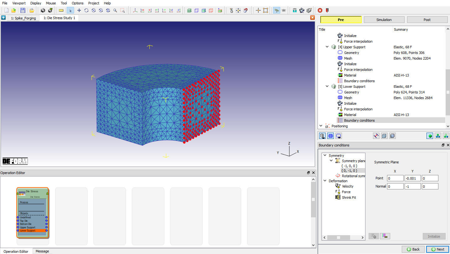
Assigning Symmetry BCC
Apply Vz = 0 Velocity boundary condition on the bottom surface so that the object does not fly off in the Z-direction. (See Fig. 3DDSL2.23.) Click on ![]() until Contact page
until Contact page
BCC Definition Window
Define Inter-Object Relation
In Contact page, click on ![]() button twice to add two relations in list. In First relation, select **Upper support** as Master and Top Die as Slave object with friction value 0.3. In second relation, select**Lower support** as Master and Bottom Die** as **Slave with friction value 0.3. Click on
button twice to add two relations in list. In First relation, select **Upper support** as Master and Top Die as Slave object with friction value 0.3. In second relation, select**Lower support** as Master and Bottom Die** as **Slave with friction value 0.3. Click on ![]() button to set a suitable tolerance and click on
button to set a suitable tolerance and click on ![]() to generate contacts. (See Fig. 3DDSL2.24.)
to generate contacts. (See Fig. 3DDSL2.24.)

Inter-Object Window
Simulation Controls
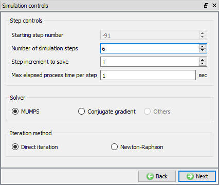
Set Number of Simulation Steps to **6** and the Step Increment to Save to 1. Set the Max. elapsed process time per step as 1 sec. (See Fig. 3DDSL2.25.)
Simulation Controls window
Generate Database
Click on ![]() action label to check the problem. Generate a database by clicking
action label to check the problem. Generate a database by clicking ![]() action label.
action label.
Once the database has been generated, switch to the Simulation mode by selecting the ![]() button above the object tree. Start the simulation by clicking the
button above the object tree. Start the simulation by clicking the ![]() action label and selecting “Start from last negative step” option. After completion of Simulation, switch to Post mode by selecting
action label and selecting “Start from last negative step” option. After completion of Simulation, switch to Post mode by selecting ![]() button.
button.
Post Processing
Click the ![]() to switch to User-Defined Object Mode, which allows you to change the appearance of the objects. Use
to switch to User-Defined Object Mode, which allows you to change the appearance of the objects. Use ![]() to turn on contact for both the Top Die and the Bottom Die and make both supports transparent by clicking the
to turn on contact for both the Top Die and the Bottom Die and make both supports transparent by clicking the ![]() icon for each.
icon for each.
This simulation was run with multiple steps so that the contact and stresses could stabilize and come to equilibrium.
Play through the steps and observe how the contact changes. The Top Die contact remains essentially the same throughout the analysis but the contact on the Bottom Die changes quite a bit. The applied load pushes the center of the die downward, causing the OD of the die to raise off of the support. At the end of the simulation, the contact has stabilized and no longer changes much from one step to the next.
Using the State Variable pull-down menu, plot Effective stress and Max Principal stress as shown in Fig. 3DDSL2.26. and Fig. 3DDSL2.27., two of the most important variables in die stress simulation.
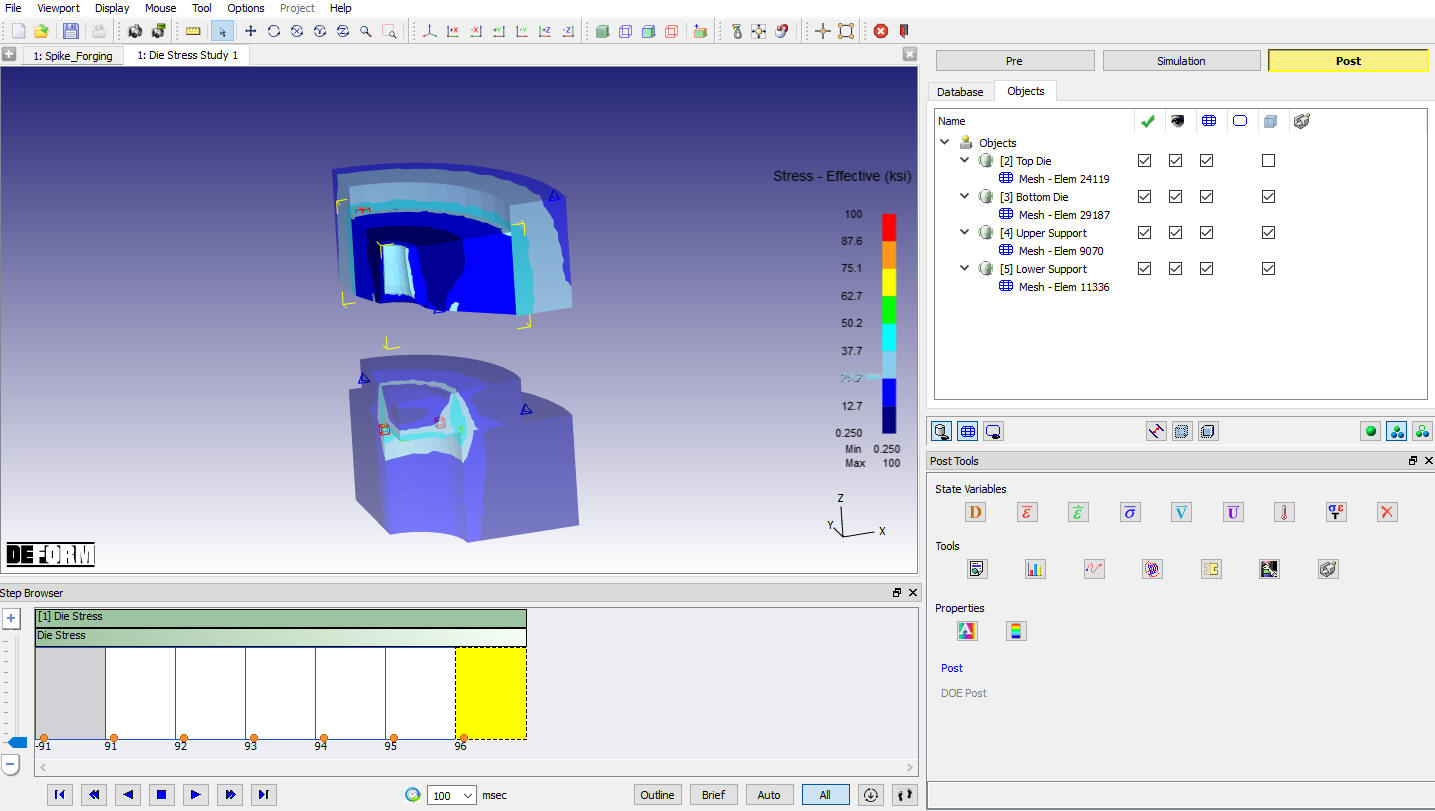
Effective Stress state variable plot
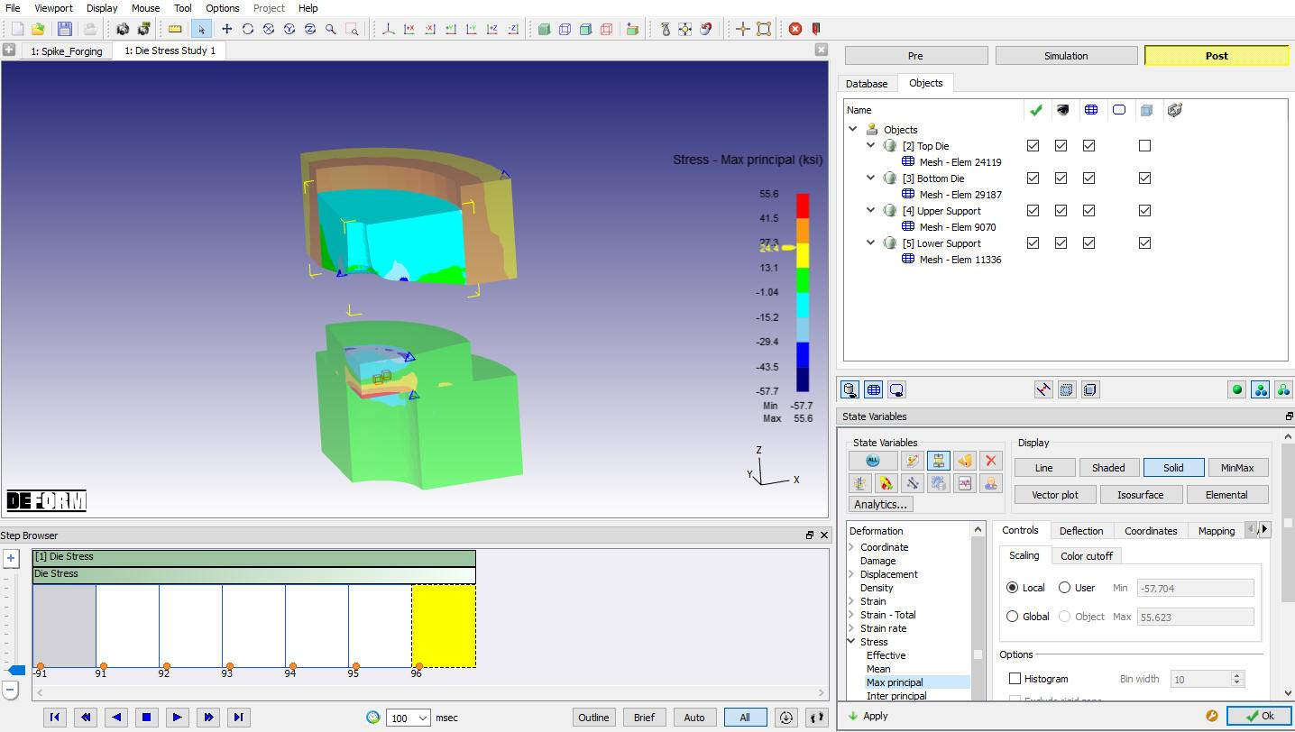
Stress-Max Principle State variable plot