39.3. 3D Milling
39.3.1. System Summary
39.3.2. Adding Milling Operation
39.3.3. Process page
39.3.4. Material List
39.3.5. Tool
39.3.5.1. Insert Geometry
39.3.5.2. Coating Material
39.3.5.3. Tool Material Selection
39.3.5.4. Tool Mesh Generation
39.3.5.5. Tool BCC
39.3.6. Workpiece
39.3.6.1. Workpiece Geometry
39.3.6.2. Workpiece Material Selection
39.3.6.3. Workpiece Mesh Generation
39.3.6.4. Workpiece BCC
39.3.7. Control
39.3.8. Tool Wear
39.3.9. Contact
39.3.10. Step Control
39.3.11. Generate DB
System Summary
DEFORM® provides machining template which can be used to setup the Milling process. The template can be used to study cutting forces, cutting temperatures, chip shape, tool wear and perform tool life computations. The engineer can study the effect of process parameters like, cutting speed, feed rate and depth of cut on the process response. The template simplifies the model definition and uses the same engineering language of process engineer. The simplified model is generated based on the feed rate and depth of cut as shown in Fig. 39.3.1. The milling tool rotates about Z axis while depth of cut is in +Y direction and feed direction is -X, feed and depth of cut will be measured from X= Z= 0.
Adding Milling Operation
To set up Milling process user need to add the 3D cutting template and select “Milling ” option in the “Process” page as shown in Fig. 39.3.2. For more details on how to add problem please refer 39.2.1. How to add 3D Cutting Operation.
Process page
The process parameters to setup milling process are as shown in Fig. 39.3.2.
Environment Heat Transfer: Environment temperature and convection co-efficient are defined under this tab, for more information on defining these parameters refer.
Cutting speed (v): It is defined as the speed at which the tool moves. The cutting speed can be defined as mm/sec or m/min in SI and in/sec or ft/min in English units.
Rotation speed : It defines the rotational speed of the tool. The rotation speed can be defined in rpm and radians/sec.
Mill diameter (D): It defines the diameter of the Mill. This diameter value will be used to generate the workpiece primitive.
Depth of cut (d): It is the thickness of metal that is removed during machining. The perpendicular distance measured between the machined surface and the uncut surface of the workpiece.
Feed rate (f): It is defined as the distance the tool travels during one revolution of the workpiece. This feed rate value gets updated in the workpiece geometry primitive page. This can be defined mm/rev or mm/sec in SI and in/rev or in/sec in English units.
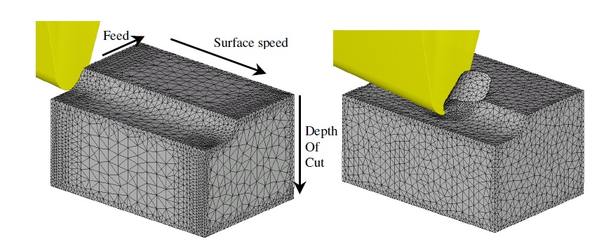
Simulation model and basic cutting parameters definition
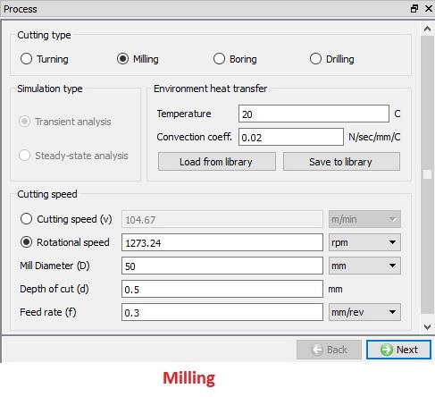
Milling type process page
Material List
In this Material List page, user can load a material from the library or keyword or database file using the ![]() ,
, ![]() options as shown in Fig. 39.3.3. The materials loaded here can be assigned to the objects from their respective material page. User can also add a new material using
options as shown in Fig. 39.3.3. The materials loaded here can be assigned to the objects from their respective material page. User can also add a new material using ![]() button and define its properties. User can use
button and define its properties. User can use ![]() button to delete the loaded material. User can also save the material using
button to delete the loaded material. User can also save the material using ![]() ,
, ![]() options.
options.
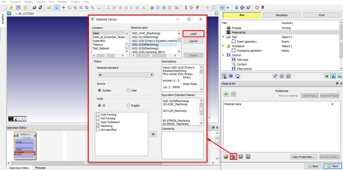
Assigning the Material to Material list
Tool
In this Tool page, the user can define the temperature of the tool object. We can import the tool object using the ![]() button (see Fig. 39.3.4.). If user wants to calculate the thermal data for tool object, select the “Calculate tool temperature ” check box and we can observe that mesh options for tool are enabled so that we can mesh the tool to calculate temperature distribution.
button (see Fig. 39.3.4.). If user wants to calculate the thermal data for tool object, select the “Calculate tool temperature ” check box and we can observe that mesh options for tool are enabled so that we can mesh the tool to calculate temperature distribution.
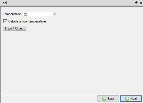
Tool Page
Insert Geometry
Milling operation do not have primitive geometry definition for tool inserts as shown in Fig. 39.3.5. User can import the tool geometry using the Import geometry ![]() options. After importing the geometry if user can re-position the tool using
options. After importing the geometry if user can re-position the tool using ![]() option.
option.
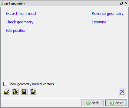
Insert geometry page
####
Defining Tool Geometry using Import geometry option
Click on ![]() and import DNMA432 geometry from DEFORM installed “\3D\Machining\Insert\SI” or “\3D\Machining\Insert\EN” folder with respect to Unit system. As the geometry is imported, a window with instructions for manual positioning is opened. If the imported tool is already in correct position, then user need not position it else user can proceed to manual positioning based on the instructions. After completing the positioning user can click on to close the window as shown in Fig. 39.3.6. The Manual positioning option are available as shown in Fig. 39.3.7.
and import DNMA432 geometry from DEFORM installed “\3D\Machining\Insert\SI” or “\3D\Machining\Insert\EN” folder with respect to Unit system. As the geometry is imported, a window with instructions for manual positioning is opened. If the imported tool is already in correct position, then user need not position it else user can proceed to manual positioning based on the instructions. After completing the positioning user can click on to close the window as shown in Fig. 39.3.6. The Manual positioning option are available as shown in Fig. 39.3.7.
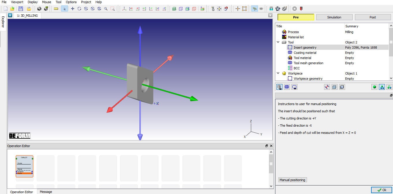
After importing the geometry, it will provide the positioning options
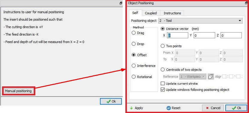
Manual positioning options
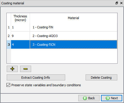
Coating Material
User can apply coating to tool insert by defining coating layer and its thickness in “Coating Material” page. User can define the coating layer material and its thickness by clicking on ![]() button as shown in the Fig. 39.3.8. If user wants to delete any layer then user has to select the respective layer and click on
button as shown in the Fig. 39.3.8. If user wants to delete any layer then user has to select the respective layer and click on ![]() button.
button.
Extract Coating Info : After Generating the coating, we can extract the coating info using this button.
Delete Coating : We can also delete the Costing layers using this button.
Using the “Preserve state variables and boundary conditions ” check box the user can create the coating layer without losing the state variable and boundary conditions data of the tool.
Coating Material Page
Tool Material Selection
In material page, all the materials added to material list are displayed as shown in Fig. 39.3.9. User can select the required material to assign it to respective object. If the desired material is not available in the list, then the user can load the material in object material page using “Import Material” data from a File ![]() or using “Load form Library” option
or using “Load form Library” option ![]() . User can also create new material if the material is not available in DEFORM library using
. User can also create new material if the material is not available in DEFORM library using ![]() . User can delete the material from list using
. User can delete the material from list using ![]() or edit the material data using
or edit the material data using ![]() . Modified / newly defined material can be saved using
. Modified / newly defined material can be saved using ![]() ,
, ![]() .
.
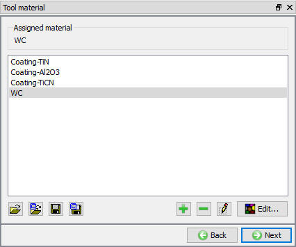
Assigning the Tool Material
Tool Mesh Generation
User can generate mesh for the tool by defining relative or absolute mesh size data as shown in the Fig. 39.3.10. & Fig. 39.3.11. It also provides the preview of the mesh when we click on ![]() option. Cutting edge information being part of the insert data, the wizard automatically applies finer mesh near the cutting zone.
option. Cutting edge information being part of the insert data, the wizard automatically applies finer mesh near the cutting zone.
Relative Mesh Method
-
Target number of elements : The number of elements to be generated for an object can be specified merely by adjusting the slider bar and selecting an appropriate value for the current simulation.
-
Size Ratio: It is the size ratio between the largest element edge length to smallest element edge length.
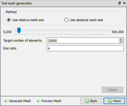
Tool Mesh Generation using relative mesh size
Absolute Mesh Method
Minimum element size : Feed rate automatically calculates the minimum element size of the mesh to be generated which calculates the Number of elements value automatically as shown in the Fig. 39.3.11.
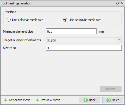
Tool Mesh Generation using absolute mesh size
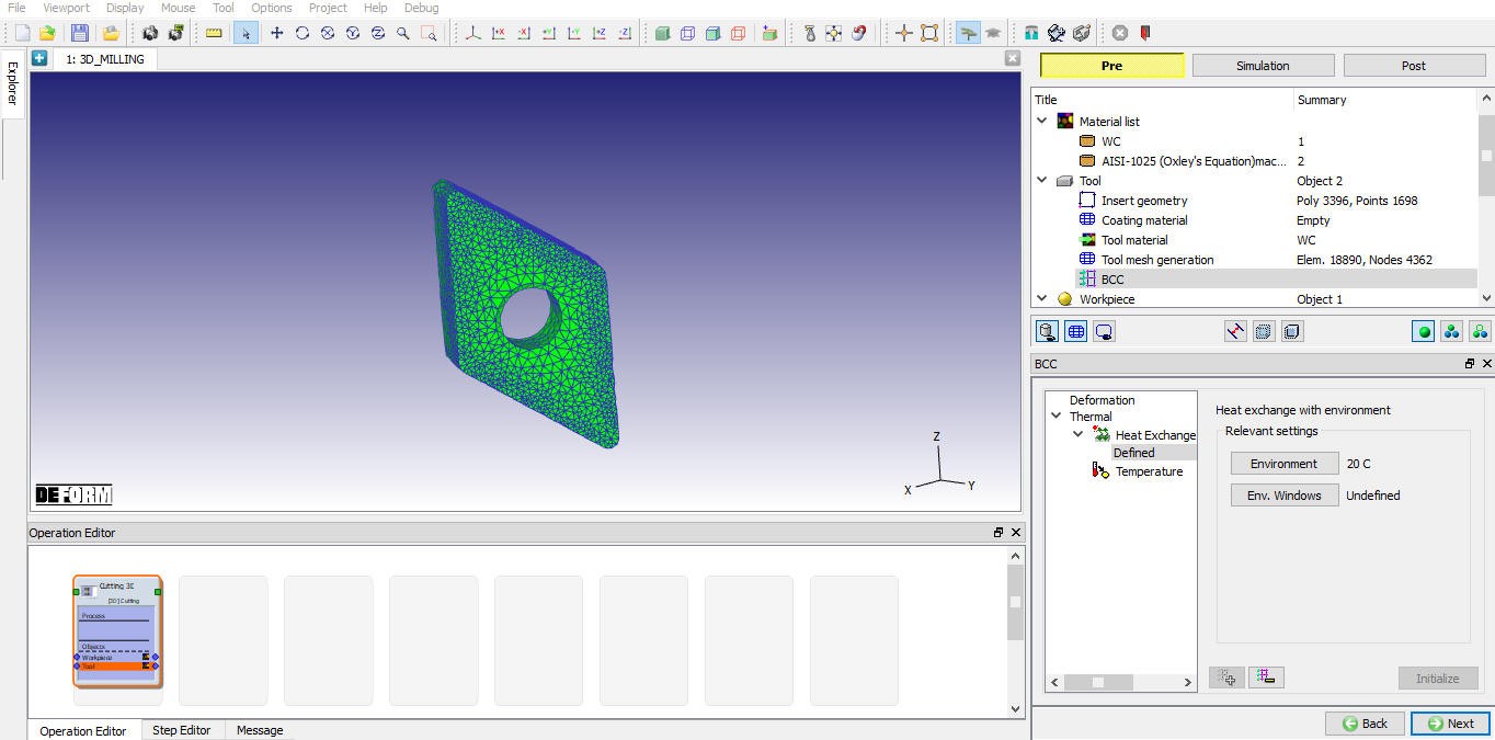
Tool BCC
In this BCC Page, the user can define the Thermal BCC like “Heat Exchange with Environment” and “Temperature”. The default BCC are assigned automatically after generating the mesh as shown in the Fig. 39.3.12.
Default Heat exchange BCC
Workpiece
In this Workpiece page, the user can define the object type and set its initial temperature. Plastic object type is selected by default as shown in Fig. 39.3.13., if user is interested to consider the effect of elastic properties then Elasto-plastic object type can be used. We can also import the object data using the ![]() button.
button.
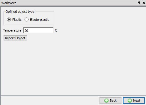
Workpiece Page
Workpiece Geometry
In this Workpiece Geometry page, the user can define the workpiece geometry using the ![]() . The user can also import the geometry using the Import geometry
. The user can also import the geometry using the Import geometry ![]() ,
,![]() options as shown in Fig. 39.3.14.
options as shown in Fig. 39.3.14.

Workpiece Geometry Page
####
Defining Workpiece Geometry using Define Primitive option
Using the ![]() we will enter the ‘Workpiece Geo Primitive’ page. In this page user need to define the geometry parameters and click on button
we will enter the ‘Workpiece Geo Primitive’ page. In this page user need to define the geometry parameters and click on button ![]() to generate geometry as shown in the Fig. 39.3.15. Based on the tool position user needs to define the start angle. User need to define the “Rotation angle” to cover the simulation process time. The workpiece will be generate using start angle, rotation angle, mill dia, feed rate and depth of cut.
to generate geometry as shown in the Fig. 39.3.15. Based on the tool position user needs to define the start angle. User need to define the “Rotation angle” to cover the simulation process time. The workpiece will be generate using start angle, rotation angle, mill dia, feed rate and depth of cut.
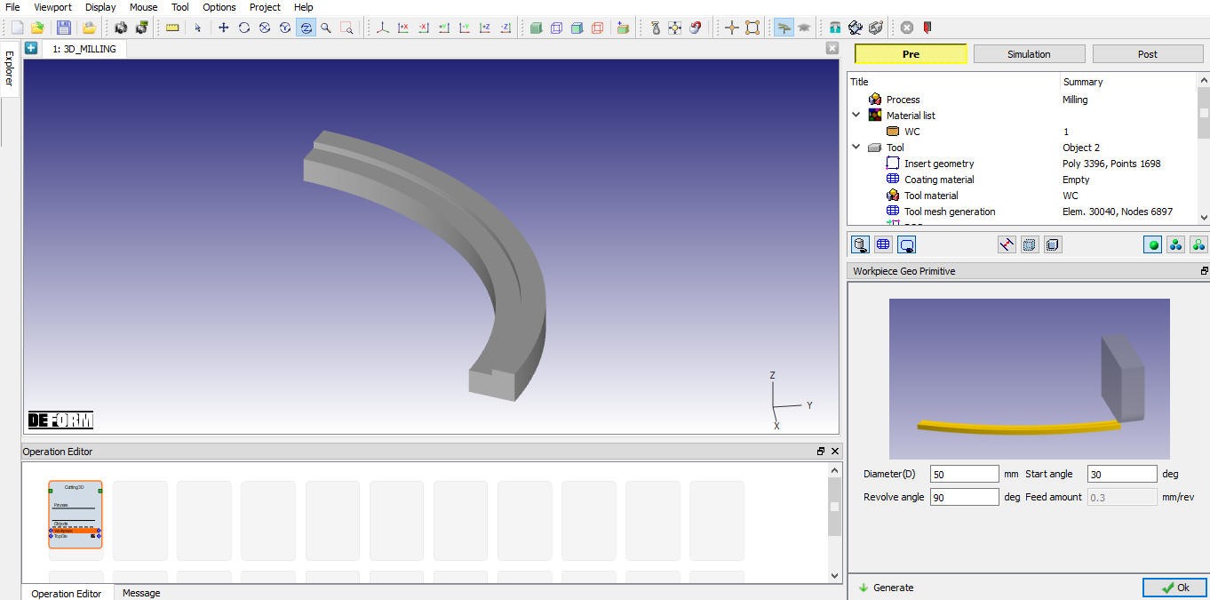
Milling Workpiece Geometry
Workpiece Material Selection
In material page, all the materials added to material list are displayed as shown in Fig. 39.3.16. User can select the required material to assign it to respective object. If the desired material is not available in the list, then the user can load the material in object material page using “Import Material” data from a File ![]() or using “Load form Library” option
or using “Load form Library” option ![]() . User can also create new material if the material is not available in DEFORM library using
. User can also create new material if the material is not available in DEFORM library using ![]() . User can delete the material from list using
. User can delete the material from list using ![]() or edit the material data using
or edit the material data using ![]() . Modified / newly defined material can be saved using
. Modified / newly defined material can be saved using ![]() ,
, ![]() .
.
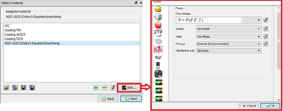
Assigning the material for the workpiece
Workpiece Mesh Generation
The User can generate the mesh by defining relative or absolute mesh size data as shown in the Fig. 39.3.17 & Fig. 39.3.18. It also provides the preview of the mesh when we click on ![]() option.
option.
Relative Mesh Method:
-
Target number of elements : The number of elements to be generated for an object can be specified merely by adjusting the slider bar and selecting an appropriate value for the current simulation.
-
Size Ratio : It is the size ratio between the largest element edge length to smallest element edge length.
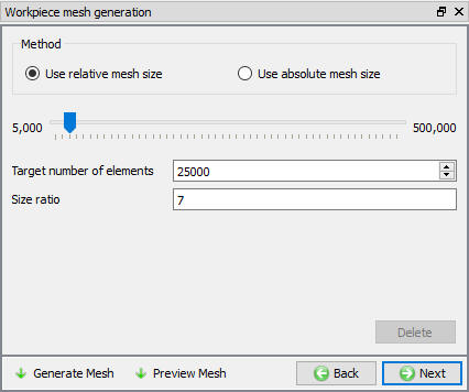
Workpiece mesh generation using relative mesh size
Absolute Mesh Method:
-
Define size by percentage of feed: The percentage of feed will automatically calculate the minimum element size of the mesh.
-
Minimum element size: It sets the minimum element size of the mesh to be generated which is calculated from the percentage of feed value.
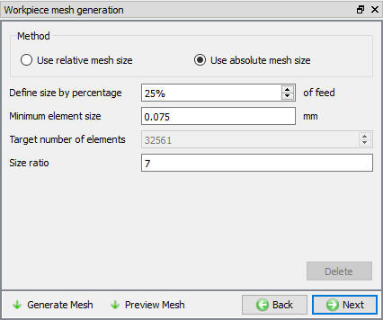
Workpiece mesh generation using absolute mesh size
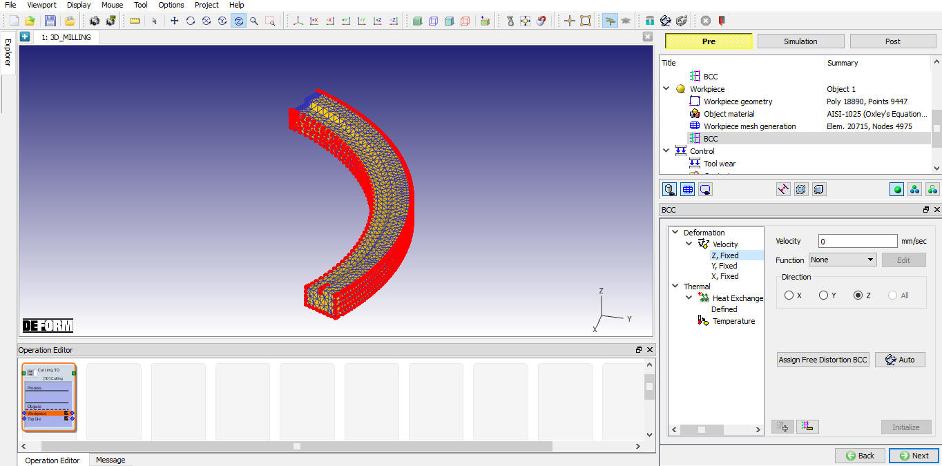
Workpiece BCC
In this BCC Page, the user can define the Deformation and Thermal BCC (like Velocity, Heat Exchange with Environment and Temperature). The BCC data will be automatically assigned after generating the mesh as shown in the Fig. 39.3.19 & Fig. 39.3.20.
Default velocity BCC has been assigned
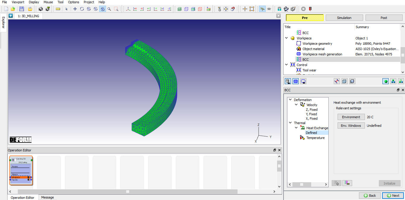
Default Heat Exchange BCC has been assigned
Control
Using “Position objects” the tool can be positioned based on the feed rate and workpiece location. Various positioning options are available to position the objects as shown in Fig. 39.3.21, for more information on these options please refer 16. Object Properties.
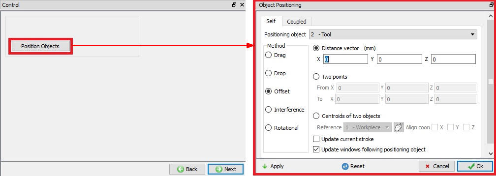
Object positioning options
Tool Wear
User can turn on tool wear calculation using “Define model to calculate tool wear ” check box. After turning on check box user can select the tool wear model and define its parameters as shown in the Fig. 39.3.22., for more information on these options please refer 20.4. Tool Wear.
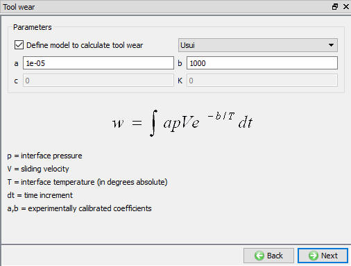
Tool Wear page
Contact
By default, user radio button will be selected and default relations also will be defined for 3D Cutting operation as shown in Fig. 39.3.23. User can modify the value of each relation by selecting it and clicking on ![]() button. User can click on
button. User can click on ![]() button to calculate contact tolerance. User can click on
button to calculate contact tolerance. User can click on ![]() to generate contact relation. User can turn on check box next to contact relation to define sticking contact.
to generate contact relation. User can turn on check box next to contact relation to define sticking contact.
For more information please refer 20. Inter-Object Relations.
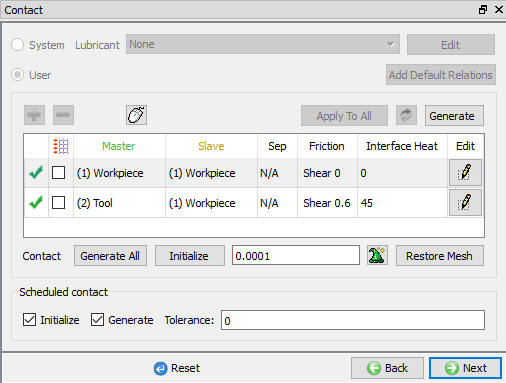
Contact page
Step Control
The user can define the step controls data using the Guided mode (![]() ) as shown in the Fig. 39.3.24. If user wants to use the advanced simulation controls than we can switch to the Expert mode (
) as shown in the Fig. 39.3.24. If user wants to use the advanced simulation controls than we can switch to the Expert mode (![]() ) as shown in the Fig. 39.3.25. For more information and description about options in Simulation controls please refer 9.Simulation Controls.
) as shown in the Fig. 39.3.25. For more information and description about options in Simulation controls please refer 9.Simulation Controls.
In Guided Mode the user can define the Number of steps, Step increment and step increment control. User can define Arc angle to cut so that simulation stops after reaching the defined Arc angle.
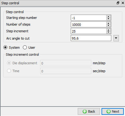
Step controls page in Guided Mode
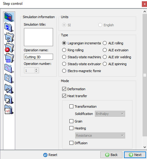
Step controls page in Expert Mode
Generate DB
Check Data ![]() : It checks the Data. If Data is correct, we can generate DB. But while checking Data if it gives any errors or warnings then it should be corrected before generating Database. Errors will not allow the database to be generated while warnings will allow the DB to be generated.
: It checks the Data. If Data is correct, we can generate DB. But while checking Data if it gives any errors or warnings then it should be corrected before generating Database. Errors will not allow the database to be generated while warnings will allow the DB to be generated.
Generate Database ![]() : By clicking on this button, it generates the Database for the setup (See Fig. 39.3.26.).
: By clicking on this button, it generates the Database for the setup (See Fig. 39.3.26.).
Append Key file : Any information that is not defined in the wizard but still applicable to the process can be loaded as .key file. This option is also useful in the cases where only few values needs to be changed then those values can be defined as .key file and only .key file can be changed, and simulation can be resubmitted.
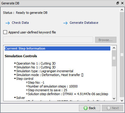
Generate DB page
Related Topics :