Lab 06 Die Stress
6.1. Introduction
6.2. Opening project file
6.3. Add Die stress study
6.4. Step selection
6.5. Top Die Setup
6.6. Bottom Die Setup
6.7. Simulation controls Setup
6.8. Generate Database
6.9. Starting the simulation
6.10. Post processing the results
Introduction
The objective of this lab is to run a die stress analysis. When the stress analysis is being done on only one tool, a one step simulation is sufficient to get accurate stresses. When the stress analysis is being done on die assemblies where there is interaction between the tools, more than one step is typically needed for the die stack to come to a state of equilibrium under the applied load.
In a typical die stress simulation, the workpiece is removed and the forces exerted onto the dies by the workpiece are interpolated onto the tools. In this lab, we are running die stress analysis for Spike_Nonisothermal project at 50th step.
Opening project file
Open Previously simulatedSpike_Nonisothermal.moproj file in DEFORM MO as shown in Fig. L6.1. MO pre- processor will open.
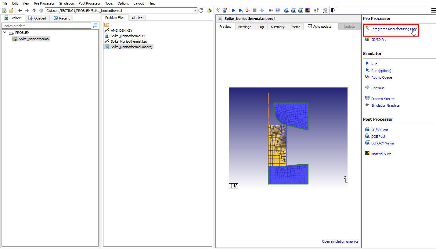
DEFORM GUI main window
Add Die stress study
At top Left corner of the Display window, Left mouse click on ![]() button and select Add Die stress Study operation as shown in Fig. L6.2. A Die stress Study tab is added with Die stress operation in operation editor as shown in Fig. L6.3.
button and select Add Die stress Study operation as shown in Fig. L6.2. A Die stress Study tab is added with Die stress operation in operation editor as shown in Fig. L6.3.
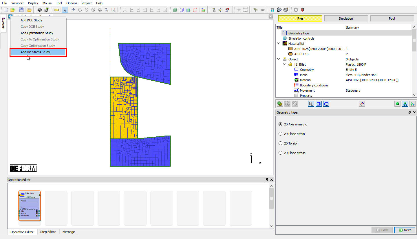
Adding Die stress operation
Step selection
To perform Die stress operation in one step, select “One step “ as Die stress calculation type and select step50 in Step selection page as shown in Fig. L6.3. Click ![]() to Top die page.
to Top die page.
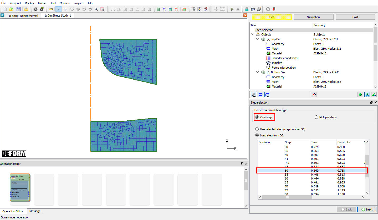
Step selection list
Top Die Setup
Top die object definition
By default, the object type of rigid objects from the loaded step will be changed to elastic. Keep the object type as elastic for the Top Die object. From v13.1.1, two new options have been introduced in the object page to position the dies in future steps for Multiple steps die stress analysis, we need not use these options for single step die stress analysis, hence, keep the Need positioning check box turned off. Click ![]() until BCC page to assign Boundary conditions.
until BCC page to assign Boundary conditions.
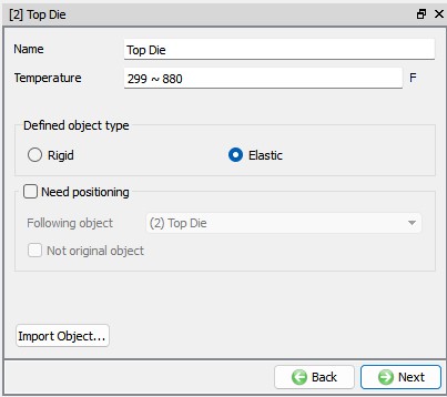
Top die object general page
Assigning Boundary condition
Apply Vy= 0 Velocity boundary condition on the top surface of the Top Die. This boundary condition prevents the die from flying off when the forces are applied, see Fig. L6.5. Click on ![]() until Top Die Force interpolation page.
until Top Die Force interpolation page.
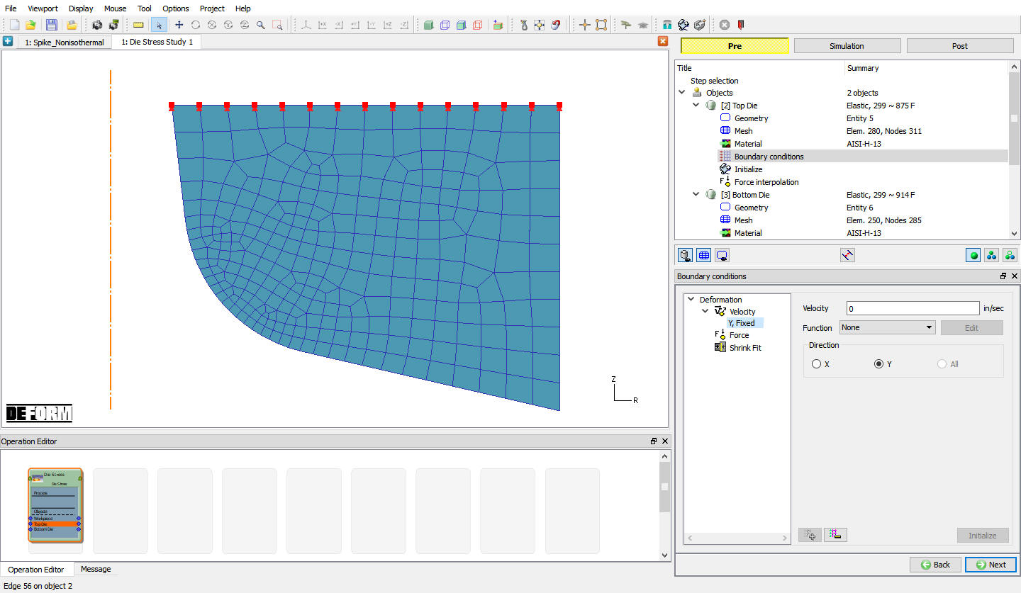
Top Die BCC page
Force interpolation
In Force interpolation page, click on ![]() action label and after force interpolation we can see the Force interpolation report in message list, see Fig. L6.6. Then click on
action label and after force interpolation we can see the Force interpolation report in message list, see Fig. L6.6. Then click on ![]() to Bottom die.
to Bottom die.

Top die Force interpolation window
Bottom Die Setup
Bottom Die object definition
We will keep the object type as Elastic for the Bottom Die and turn off Need positioning check box. Click ![]() until BCC page to assign Boundary conditions.
until BCC page to assign Boundary conditions.
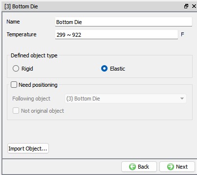
Bottom die object page
Assigning Boundary condition for Bottom Die
Apply Vy = 0 Velocity boundary condition on the Bottom surface of the Bottom Die. This boundary condition prevents the die from flying off when the forces are applied, see Fig. L6.8. Click on ![]() until Bottom die Force interpolation page.
until Bottom die Force interpolation page.
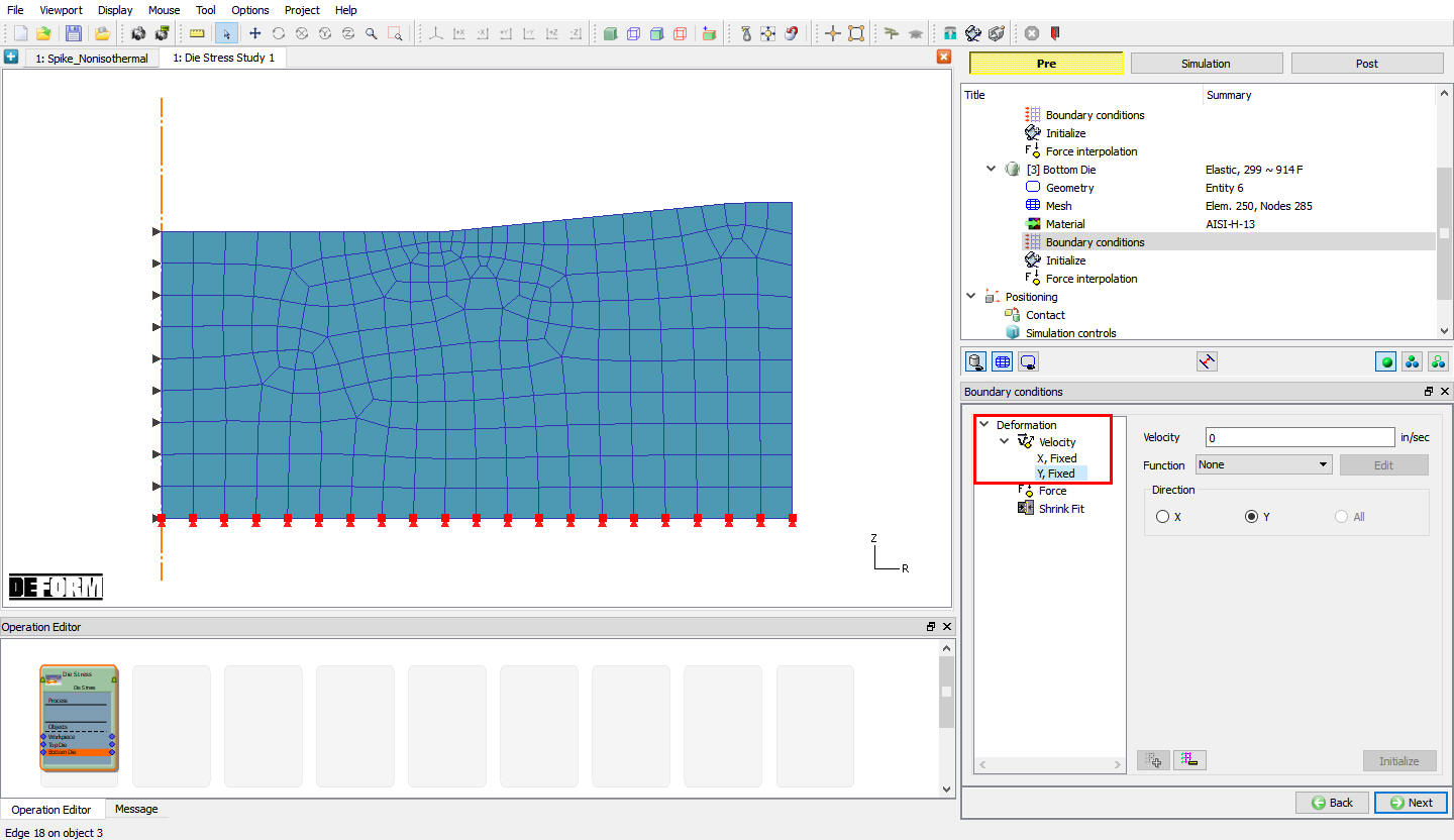
Bottom die BCC page
Force interpolation
Click on ![]() action label and after force interpolation we can see the Force interpolation report in message list, see Fig. L6.9. Then click on
action label and after force interpolation we can see the Force interpolation report in message list, see Fig. L6.9. Then click on ![]() until Simulation controls.
until Simulation controls.
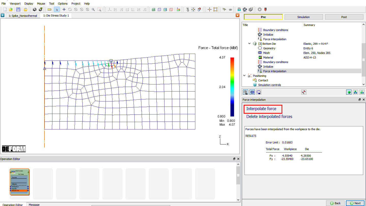
Force interpolation window
Simulation controls Setup
In this operation we will use default Simulation controls data. Click on ![]() to Generate DB page.
to Generate DB page.
Generate Database
Click on ![]() action label to check the problem. Generate a database by clicking
action label to check the problem. Generate a database by clicking ![]() action label.
action label.
Starting the simulation
Once the database has been generated, switch to the Simulation mode by clicking on ![]() button above the operation tree. Click on the
button above the operation tree. Click on the ![]() action label to open the Run Options dialog Use the default Continue Run option to select “Continue from the last step ” option and then select the Simulation mode as Interactive and click on
action label to open the Run Options dialog Use the default Continue Run option to select “Continue from the last step ” option and then select the Simulation mode as Interactive and click on ![]() button to run the simulation.
button to run the simulation.
When the simulation is finished without any issues, the following message will be added to the end of the Message file:” Simulation is completed and stopped at the user specified time step”.
Post processing the results
After simulation complete switch to post mode by clicking on ![]() button. (See Fig. L6.10.)
button. (See Fig. L6.10.)
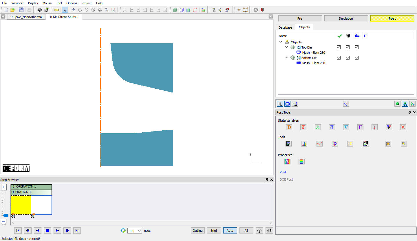
MO Post window
State Variable
Click on ![]() button, plot Effective stress and Max Principal stress and observe the plot as shown in Fig. L6.11. and Fig. L6.12. These two are the most important variables in die stress simulation.
button, plot Effective stress and Max Principal stress and observe the plot as shown in Fig. L6.11. and Fig. L6.12. These two are the most important variables in die stress simulation.

Stress Effective plot in Solid shading display
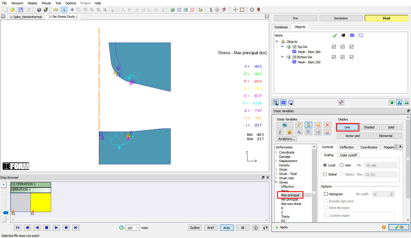
Max Principal stress plot in Line display
In order to continue with the Die Stress Labs with Holder and with Holder and Shrink Fit do not close the MO project Refer the Lab 12 Die Stress with Holder and 13 Die Stress with Shrink Fit respectively.
Related Topics:
11. General Object Data Definition
6.2. Integrated Manufacturing Process Simulation layout
6.3. Integrated Manufacturing Process Post-processor layout
2D Die Stress Study with Single step