15.8. Path
15.8.1. Local and Global Co-ordinates
15.8.2. Align Rotation center to object center
15.8.3. Synchronize with the defined path data
[2D, 3D] : Path movement can be defined in one of two ways, as a Function of time or as a Profile+feed rate.
When position is a function of time, movement is linearly interpolated between each of the defined positions.
When position is a function of feed rate, each specified feed rate [FeedRate(i)] defines how fast the object moves from the associated position [Position(i)] to the next position [Position(i+1)]. The feed rate of the last data pair will automatically be set to zero, since it has no practical purpose.
G-Code programs typically define paths using position as a function of feed rate. It should be noted that the feed rate and position relationship is slightly different than that used in DEFORM. In G-Code, each specified feed rate [FeedRate(i)] defines how fast the object moves to the associated position [Position(i)] from the previous position [Position(i-1)].
The difference in feed rate formats must be accounted for when importing G-Code paths for use as DEFORM paths. Conversion may be accomplished by shifting the feed rates one position forward in the path table. In other words, each feed rate (i) must be shifted to the previous position data pair (i-1).
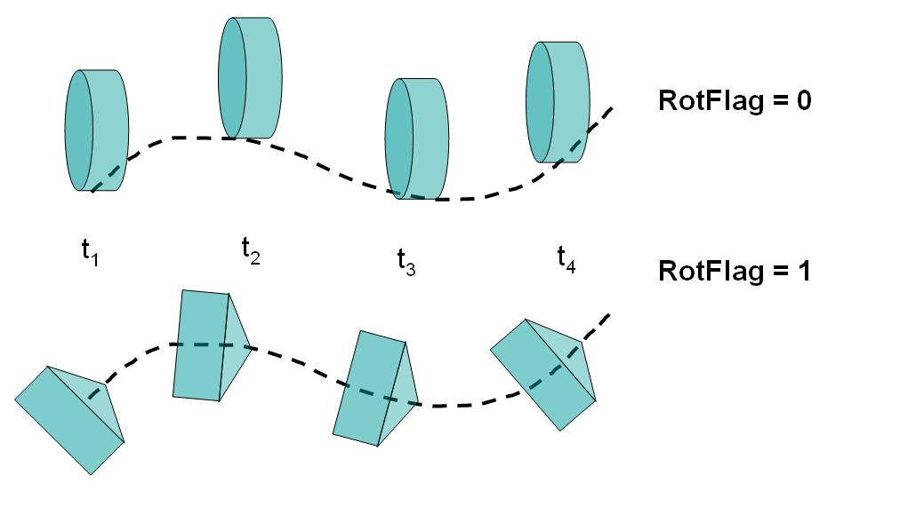
Movement along a path and along a path with alignment
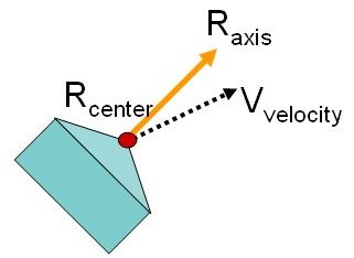
Directionality of axis and velocity vectors with respect a reference point on the object
As a first step to define path movement data user enters the path movement control dialog. (See Fig. 15.8.3. and Fig. 15.8.4.)

2D User interface to enter path movement definition
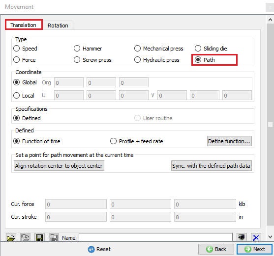
3D User interface to enter path movement definition
[2D] : 2D Path movement can be defined by X and Y positions, regardless of the function type utilized.
Local and Global Co-ordinates [3D]
InGlobal co-ordinates used when object to be moved in the X, Y and Z directions by defining position values along these three directions as function of time or function of feed rate.
If translational movement of a rotating roller is limited on the plane Its movement can be described on this plane in a local coordinate system. When the local plane can be defined using two vectors (U,V), the movement on its local plane can be easily defined. The following figure (See Fig. 15.8.5.) illustrates this in a flow forming application where the rollers are moving radially and axially only on a plane passing through the center of the roller and the axis of the work piece.

Basic concepts of a local plane with illustration
The data for the local plane needs to be defined, concepts for which are illustrated in Fig. 15.8.6.
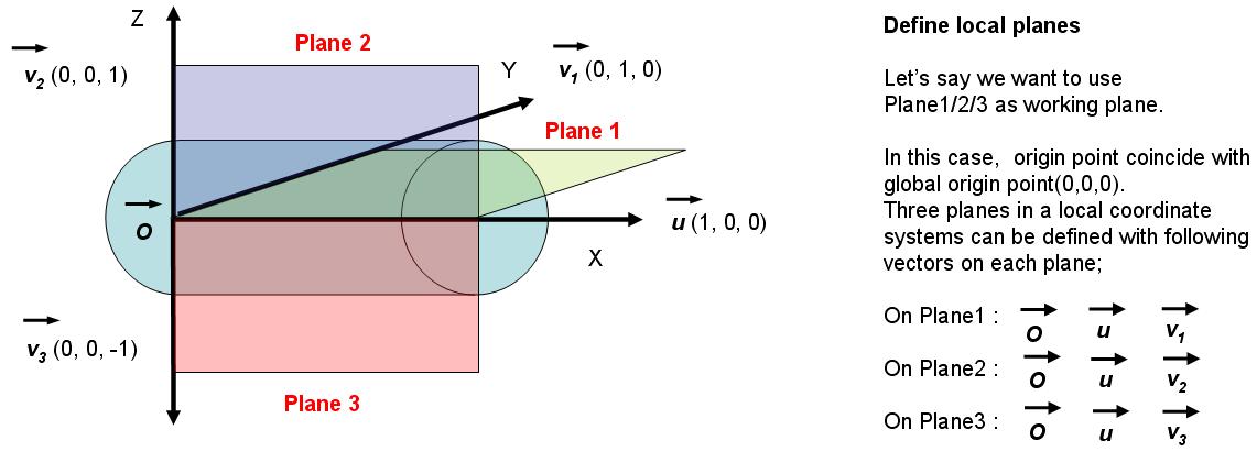
Data needed to define a local plane
As illustrated in Fig. 15.8.7., this function data can represents a complex movement which in a simple form can be time and position data on a local plane with a specific orientation in space.
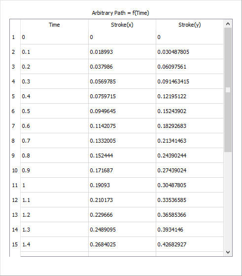
Function data table in local plane
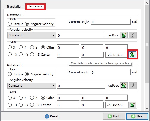
Align Rotation center to object center [2D, 3D]
When alignment is involved object rotation center (square marker in Fig. 15.8.8.) and the geometry center (circle marker in Fig. 15.8.8.) needs to be aligned for the movement to follow the path with proper orientation from time to time. User can specify object center as the reference point. (shown as axis center under the Rotation tab in Movement GUI, See Fig. 15.8.12. and Fig. 15.8.13.
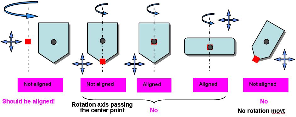
Basics of alignment and rotation, with respect to the geometry center
Synchronize with the defined path data [2D, 3D]
After the user specify the reference point, assign the movement by synchronizing it with the defined function data. Since “Synchronization” means an update of the object data based on the time-dependent path movement data in “time” and “space” domains. For synchronization, the current simulation time is used as a reference time. Once this synchronization is done object position can change (with a system message as indicated in Fig. 15.8.9.) based on the current process time (See Fig. 15.8.10.) and the function data type (See Fig. 15.8.11.) defined for this path movement. Also go through the Fig. 15.8.14. for the path movement depicted on the local plane.
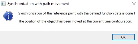
System messages when synchronization is attempted with reference point
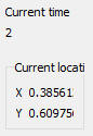
Current time

Plot type
Finding geometry center
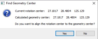
Options to align rotation and geometry center once computed
Positioning concepts when path function data is defined
Related Topics: