Lab06 Hot Forming Labs
In this lab we will setup Tee forging operation using MO Forming operation.
Lab 1. Operation 1: Upsetting operation
1.1. Creating a New Problem
1.2. Adding 3D Forming operation
1.3. Simulation Controls
1.4. Adding Objects
1.5. Workpiece
1.6. Import Workpiece Geometry
1.7. Workpiece mesh Generation
1.8. Assign Material for Workpiece
1.9. Top Die Definition
1.10. Import Top Die geometry
1.11. Assign Top Die movement
1.12. Bottom Die Definition
1.13. Import Bottom Die Geometry
1.14. Object Positioning
1.15. Contact (Inter object Relation) Definition
1.16. Stopping Controls Definition
1.17. Step Controls
1.18. Generate Database
1.19. Running simulation
1.20. Post process the upsetting operation
Lab 2. Operation2 - Finish Forge operation
2.1. Add and Define 2nd operation
2.2. Scheduled positioning
2.3. Contact (Inter object Relation) Definition
2.4. Stopping controls
2.5. Step Controls
2.6. Generating DB
2.7. Running simulation
2.8. Post processing finishing operation
Operation 1: Upsetting operation
Creating a New Problem
On a Windows machine , go to the ![]() button select DEFORM-v1x.xxx (.xxx indicates version number E.g. v14.0.2) and select DEFORM GUI Main vxx.xx from the menu. The DEFORM GUI Main window will appear as shown below Fig. L1.1.
button select DEFORM-v1x.xxx (.xxx indicates version number E.g. v14.0.2) and select DEFORM GUI Main vxx.xx from the menu. The DEFORM GUI Main window will appear as shown below Fig. L1.1.
Creating New project from GUI Main
Create a new problem either by selecting File ![]() New Problem or by clicking the New Problem
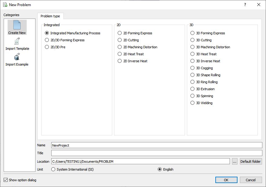
New Problem or by clicking the New Problem ![]() icon. The Problem Setup window will appear as shown in 1. Select “Integrated Manufacturing Process “ radio button and unit system as “English “ radio button in Unit field. Define Problem Name as “Tee “ and make sure the “Show option dialog ” check box is turned on (if we do not turn on the “Show option dialog” check box, then we will not get the New Project dialog). Then click on
icon. The Problem Setup window will appear as shown in 1. Select “Integrated Manufacturing Process “ radio button and unit system as “English “ radio button in Unit field. Define Problem Name as “Tee “ and make sure the “Show option dialog ” check box is turned on (if we do not turn on the “Show option dialog” check box, then we will not get the New Project dialog). Then click on ![]() button to open a new problem using the Deform Integrated Manufacturing Process.
button to open a new problem using the Deform Integrated Manufacturing Process.
MO wizard will open along with New Project window (See Fig. L1.2.), defined problem name ‘Tee ’ is updated as the project name along with unit system. Click on ![]() to continue to open the operation.
to continue to open the operation.
If required, user can change the Unit system and add operation by selecting respective operation from First operation pull down list and turning on checkbox and using Copy Existing project option, user can import previous saved projects as new project.

New Project definition window in MO
Adding 3D Forming operation
Once you click on ![]() button, a Multiple Operation wizard will open to setup the problem. Add 3D Forming operation from Operations list in Explorer, operation can be added by clicking on
button, a Multiple Operation wizard will open to setup the problem. Add 3D Forming operation from Operations list in Explorer, operation can be added by clicking on ![]() button next to 3D Forming operation(See Fig. L1.3.) or user can also add by drag and drop into the Operation Editor.
button next to 3D Forming operation(See Fig. L1.3.) or user can also add by drag and drop into the Operation Editor.
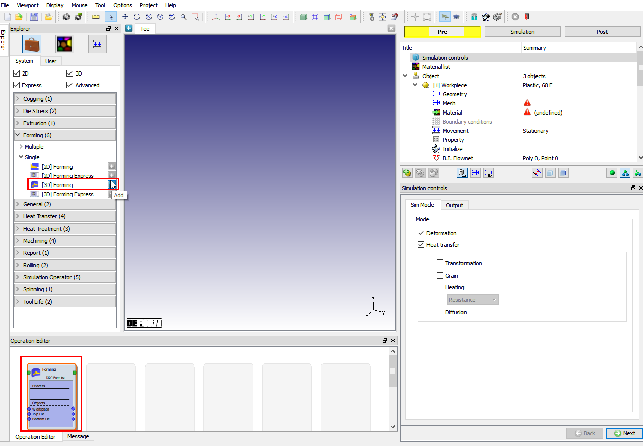
Adding 3D Forming operation
Simulation Controls
This lab is an isothermal setup so, in Simulationcontrols page uncheck the Heattransfer mode check box (See Fig. L1.4.). Then click ![]() .
.
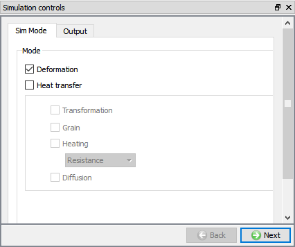
Selecting Simulation mode
Adding Objects
For this operation we required three objects, if there aren’t already three objects, add three objects by clicking the ![]() button. The three objects will be named as Workpiece, Top Die and Bottom Die, see Fig. L1.5., then click on
button. The three objects will be named as Workpiece, Top Die and Bottom Die, see Fig. L1.5., then click on ![]() .
.
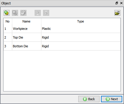
Adding objects in object page
Workpiece
Change the Workpiece Temperature to 2150 °F as shown in Fig. L1.6. Click on ![]() .
.
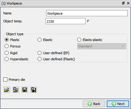
Workpiece Object page
Import Workpiece Geometry
In Geometry page, click on ![]() (Load material data from library) button, import TeeBillet.stl file from /3D/Labs/ folder as shown in Fig. L1.7.
(Load material data from library) button, import TeeBillet.stl file from /3D/Labs/ folder as shown in Fig. L1.7.
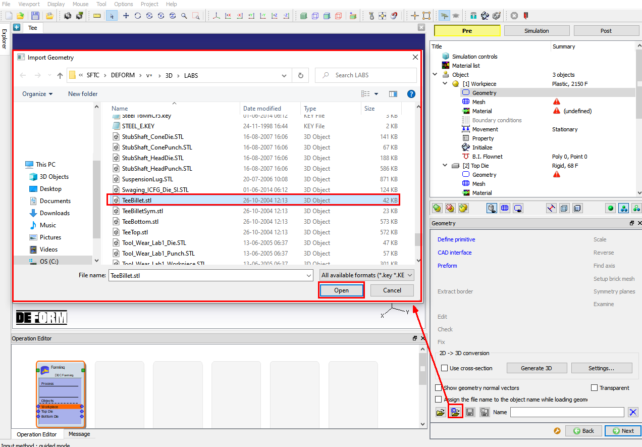
Importing Workpiece geometry
Check the geometry by clicking on ![]() action label. The “Geometry Checking Result” window will pop-up with description of geometry checking result along with description of what constitutes a legal geometry as shown in Fig. L1.8. Click
action label. The “Geometry Checking Result” window will pop-up with description of geometry checking result along with description of what constitutes a legal geometry as shown in Fig. L1.8. Click ![]() .
.

Check geometry output page
Workpiece mesh Generation
Define target number of elements as 32000 and click on ![]() option as shown in Fig. L1.9. Different type of settings for mesh are accessible from expert mode but in this lab, we will be using default settings for mesh. Generated mesh for Workpiece looks like as shown in Fig. L1.9. Click
option as shown in Fig. L1.9. Different type of settings for mesh are accessible from expert mode but in this lab, we will be using default settings for mesh. Generated mesh for Workpiece looks like as shown in Fig. L1.9. Click ![]() .
.
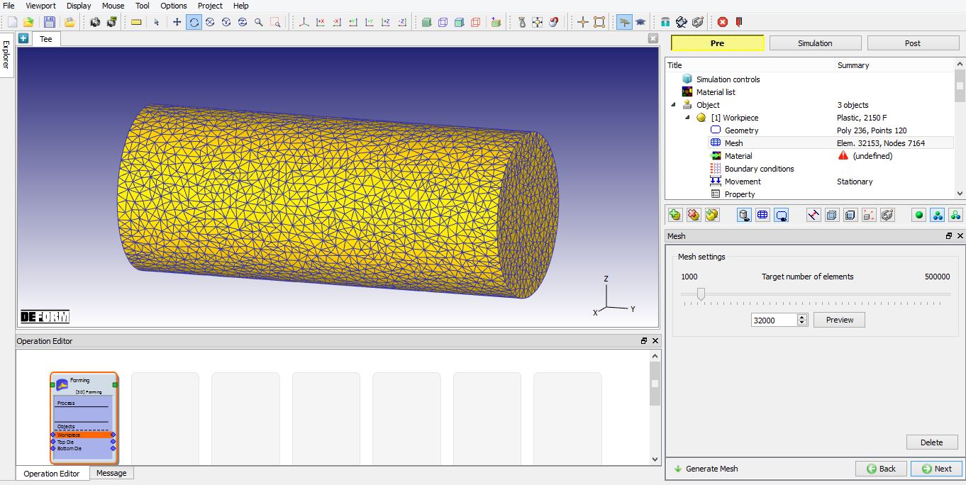
Generating mesh for Workpiece
Assign Material for Workpiece
In Material window, load the material AISI-316[70-2020F(20-1100C)] from DEFORM Material library, from Stainlesssteel category using ![]() (Load material data from library) button. This can be done as shown in below Fig. L1.10. by clicking
(Load material data from library) button. This can be done as shown in below Fig. L1.10. by clicking ![]() button in Material Library window. Material can also be loaded from Materials list in Explorer. Click on
button in Material Library window. Material can also be loaded from Materials list in Explorer. Click on ![]() until Top Die page.
until Top Die page.
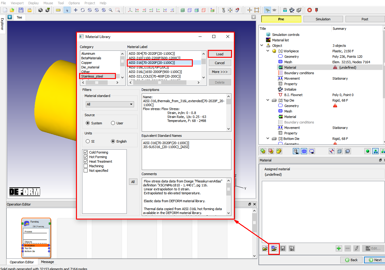
Loading material for Workpiece
Top Die Definition
In Top Die page, define the Object Temperature as 300°F as shown in Fig. L1.11., click ![]() .
.
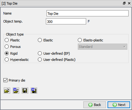
Top Die object page
Import Top Die geometry
Click on ![]() (Load Geometry from Library) button, import TeeTop.stl file from /3D/Labs/ folder as shown in Fig. L1.12. Then check the geometry using
(Load Geometry from Library) button, import TeeTop.stl file from /3D/Labs/ folder as shown in Fig. L1.12. Then check the geometry using ![]() label in Geometry page. Click
label in Geometry page. Click ![]() .
.

Importing geometry for Top Die
Assign Top Die movement
Under the movement page, select speed movement type, be sure movement is in the –Z direction and then enter 10 in/sec as Constant value as shown in Fig. L1.13. Top Die will move with a speed of 10 in/sec. Click ![]() .
.
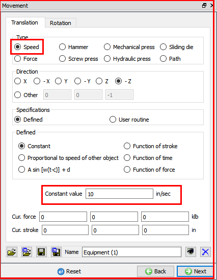
Defining movement for Top Die
Bottom Die Definition
In Bottom Die page, define the Object Temperature as 300° F, click ![]() .
.
Import Bottom Die Geometry
Click on ![]() (Load Geometry from Library) button, import TeeBottom.stl file. Then check the geometry using
(Load Geometry from Library) button, import TeeBottom.stl file. Then check the geometry using ![]() label from Geometry page. Click
label from Geometry page. Click ![]() .
.
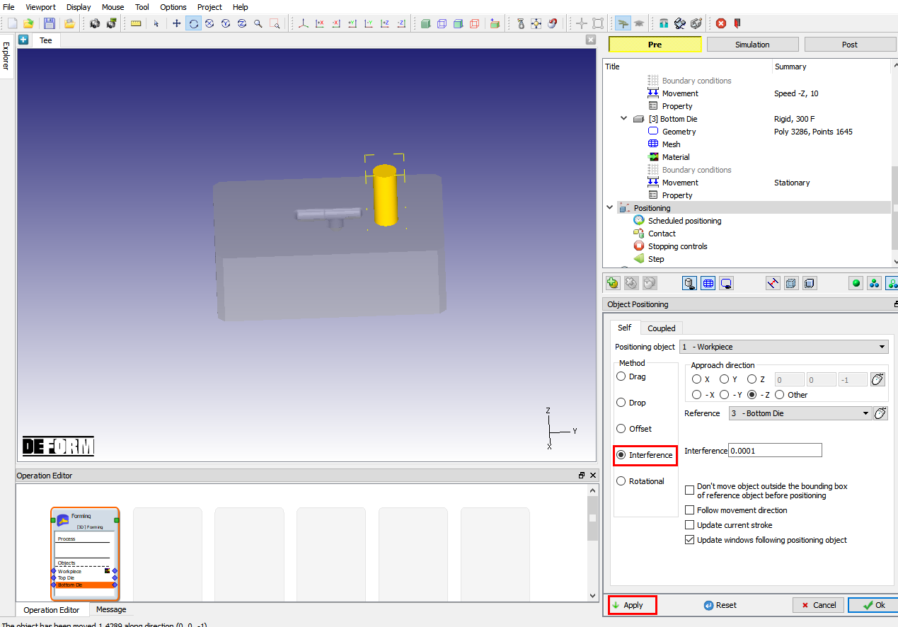
Object Positioning
We will perform this operation with the Workpiece in vertical direction. We will first position the Workpiece on the Bottom Die. To make it easier to see, change to “User Defined Object Display” mode in the control bar at the bottom of the object tree. Select Top Die in Object mode window and uncheck the check box in Visible column as shown in Fig. L1.14., then click ![]() .
.
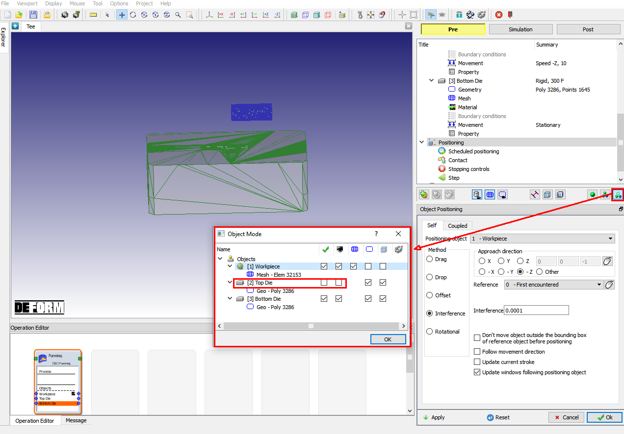
User define Object display selection and Object positioning page
Click on ![]() button. Object positioning page will open as shown in Fig. L1.14. Select “Rotational ” positioning and then select Workpiece as positioning object. Use the mouse to pick a point around the center of the Workpiece, and then select the “X ” axis as the axis of rotation. Enter an angle of 90 degrees, and then click on
button. Object positioning page will open as shown in Fig. L1.14. Select “Rotational ” positioning and then select Workpiece as positioning object. Use the mouse to pick a point around the center of the Workpiece, and then select the “X ” axis as the axis of rotation. Enter an angle of 90 degrees, and then click on ![]() . The Workpiece should now be positioned vertically, see Fig. L1.15.
. The Workpiece should now be positioned vertically, see Fig. L1.15.
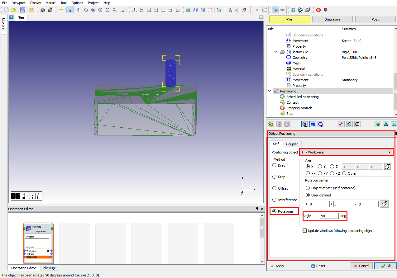
Object positioning window page
Switch to “Drag ” positioning and use the mouse to drag the Workpiece to a flat spot on the die as shown in Fig. L1.16., not too close to either the forming cavity or the edge of the die. Now we will use “Interference ” positioning to place the Workpiece on the Bottom Die.
Positioning the workpiece on bottom die
Click on User defined mode ![]() and check the Top Die visible check box. Now, position Top Die using Interference Positioning on Workpiece so that it is in contact with the Workpiece. Click
and check the Top Die visible check box. Now, position Top Die using Interference Positioning on Workpiece so that it is in contact with the Workpiece. Click ![]() .
.
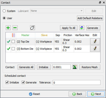
Contact (Inter object Relation) Definition
Select Usertype contact and click on ![]() button. It will add the relationship between the Workpiece, Top Die and Bottom Die shown in Fig. L1.17.
button. It will add the relationship between the Workpiece, Top Die and Bottom Die shown in Fig. L1.17.
Highlight the Top Die – Workpiece relationship and then click on the ![]() button to modify the relationship. In the friction tab, see Fig. L1.18., there is a drop down box for Constant field that allows the user to choose the appropriate friction conditions of common forming processes, selectHot forging (lubricated) from drop down box, a friction value of 0.3 will be added to the Constant friction field.
button to modify the relationship. In the friction tab, see Fig. L1.18., there is a drop down box for Constant field that allows the user to choose the appropriate friction conditions of common forming processes, selectHot forging (lubricated) from drop down box, a friction value of 0.3 will be added to the Constant friction field.
Click ![]() to go back to Inter-Object window. Since the friction conditions are the same for all the object pairs,
to go back to Inter-Object window. Since the friction conditions are the same for all the object pairs, ![]() button can be used to copy the interface properties from the first relationship to all others. After this is done, all relationships will have a friction of 0.3 defined. Use
button can be used to copy the interface properties from the first relationship to all others. After this is done, all relationships will have a friction of 0.3 defined. Use ![]() icon to determine a suitable contact tolerance (a value of about 0.001169” will be calculated), then click
icon to determine a suitable contact tolerance (a value of about 0.001169” will be calculated), then click ![]() button to generate contact. If you rotate the objects around in graphics window, you will see that contact was generated between the two objects. Click on
button to generate contact. If you rotate the objects around in graphics window, you will see that contact was generated between the two objects. Click on ![]() until Stopping controls window.
until Stopping controls window.
Contact page showing contact pairs
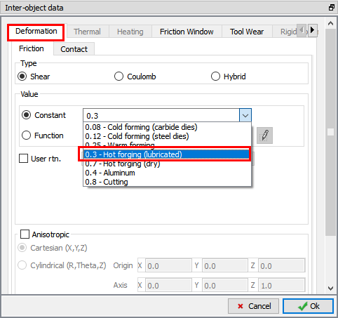
Defining Friction value from drop down box
Stopping Controls Definition
We will stop when the dies are 1.500” apart. So, set “Stop Controls” to “Distancebetween objects “ and enter a value of 1.5 ” in Z direction as shown in Fig. L1.19. To define stopping distance between dies, turn on shaded mode using ![]() , select a point on the bottom surface of the top die, and then second point on the top surface of the bottom die. Click
, select a point on the bottom surface of the top die, and then second point on the top surface of the bottom die. Click ![]() to Step page.
to Step page.
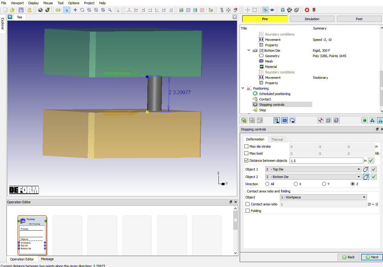
Defining Distance between dies stopping controls
Step Controls
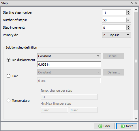
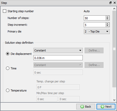
In Step page, change the Numberof Steps to 50 , set increment to save as 5 and Solution step definition as 0.036 Die displacement (See Fig. L1.20.), then click ![]() .
.
Step control page
Generate Database
In Generate DB page. Click the ![]() button to have the program check to see if anything was missed in the problem setup. During the checking process:
button to have the program check to see if anything was missed in the problem setup. During the checking process:
Messages in the red color signify data that needs to be fixed before a simulation can be run (such as when you forget to define any material data).
Click on ![]() button to generate the database. When the program is done writing the database, click on
button to generate the database. When the program is done writing the database, click on ![]() tab to run simulation.
tab to run simulation.
Running simulation
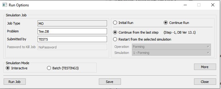
Click on the ![]() action label to open the Run Options dialog Use the default Continue Run option to select “Continue from the last step ” option as shown in Fig. L1.21., then select the Simulation mode as Interactive and click on
action label to open the Run Options dialog Use the default Continue Run option to select “Continue from the last step ” option as shown in Fig. L1.21., then select the Simulation mode as Interactive and click on ![]() button to run the simulation.
button to run the simulation.
.
Run simulation window page
The progress of the simulation can be monitored while it is running by looking at the Simulation Message tab and Simulation Graphics from the Graphics display region in Simulation mode. As long as ![]() option is checked in Simulation Message tab, which is the default setting, the Message file will refresh automatically.
option is checked in Simulation Message tab, which is the default setting, the Message file will refresh automatically.
The Message file provides information about which simulation step the simulation is currently on and gives information dealing with how well the simulation is running.
When the simulation is finished without any issues, check the messages in Message file, when operation completes we will see messages as “THE DISTANCE BETWEEN TWO OBJECTS ( 2 3): 1.5000000 HAS REACHED THE SPECIFIED LIMIT 1.5000000 “
Post process the upsetting operation
After completion of simulation, switch to ![]() mode to view simulation output. Click on
mode to view simulation output. Click on ![]() button in Step Browser to see all saved steps as shown in Fig. L1.22.
button in Step Browser to see all saved steps as shown in Fig. L1.22.
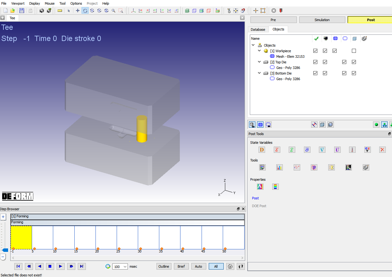
Step browser in MO Post showing all saved steps
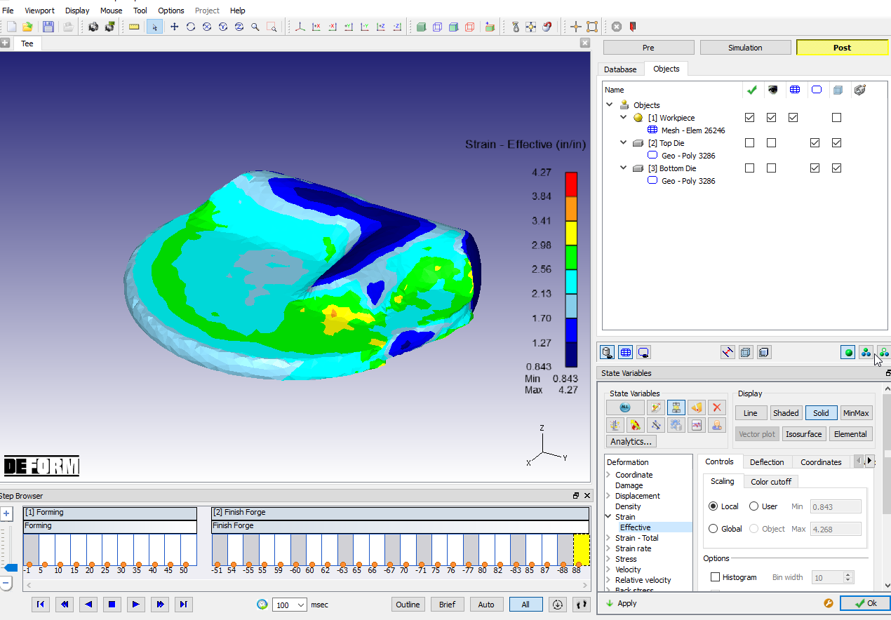
State Variable:
From the state variable menu, click on ![]() button, select “Stress
button, select “Stress![]() Effective ” variable, display type as Solid and then click on
Effective ” variable, display type as Solid and then click on ![]() as shown in Fig. L1.23., you can also view state variable output in elemental, line or shaded contours. Experiment with each of these settings.
as shown in Fig. L1.23., you can also view state variable output in elemental, line or shaded contours. Experiment with each of these settings.
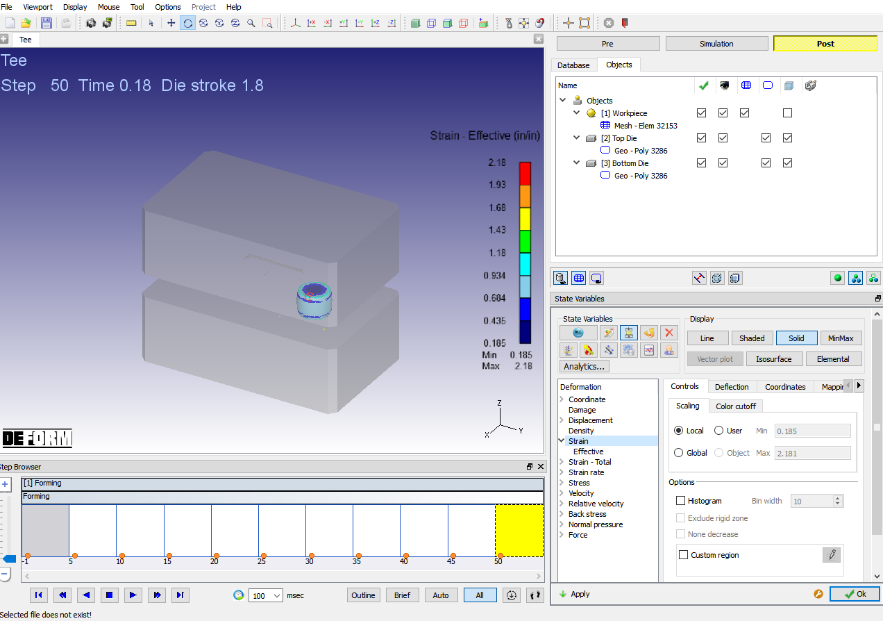
Effective Stress distribution in the workpiece at the end of first operation
Point Tracking:
Select ![]() point tracking. Select few points on the object, and track the points using
point tracking. Select few points on the object, and track the points using ![]() option (See Fig. L1.24.). If a state variable is displayed, then the values of the variables will be graphed at these points.
option (See Fig. L1.24.). If a state variable is displayed, then the values of the variables will be graphed at these points.
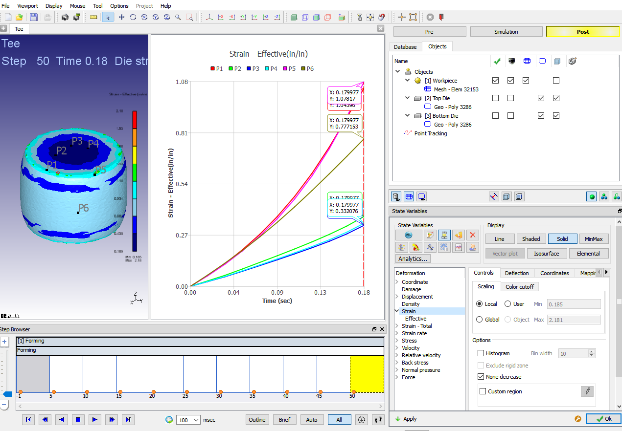
Point tracking output of Effective strain
Operation2 - Finish Forge operation
After completion of simulation and post-processing, switch to ![]() mode.
mode.
Add and Define 2nd operation
Add another Forming operation to setup Finish Forge operation. In this operation we will be positioning the Workpiece over the cavity in Die and simulating the Finish Forge operation.
Select batch mode:
Select 2nd operation from Operation editor, “Setup type” popup will appear, click on ![]() button in popup as we would like to set up second operation in Batch mode.
button in popup as we would like to set up second operation in Batch mode.
Change operation name:
Change operation name to “Finish Forge “ from Operation editor by double clicking on the operation name as shown in Fig. L2.1. and then click on enter button to finish editing.
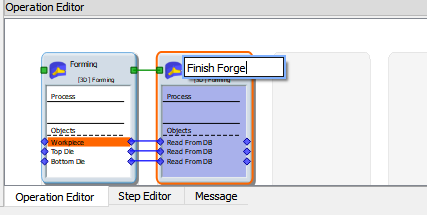
Changing operation name in operation editor page
Scheduled positioning
Since all objects are Read from DB and there is no change in mesh settings or BCC, we will navigate to Postioning Page. In Controls page, click on Schedule positioning. In Scheduled positioning page, add relation by clicking on ![]() button. Click on
button. Click on ![]() to define schedule positioning, select positioning object as Workpiece and positioning type as Offset, define “Y ” as -3.4 to position the workpiece on Die cavity.
to define schedule positioning, select positioning object as Workpiece and positioning type as Offset, define “Y ” as -3.4 to position the workpiece on Die cavity.
Similarly add relations to position Top die on Workpiece in -Z direction and Bottom Die below Workpiece in +Z Direction using Interference positioning options as shown in Fig. L2.2. The object positioning will be executed before generating DB. Click ![]() .
.
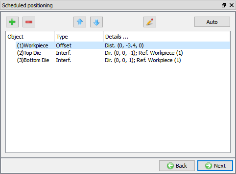
Defining schedule positioning
Contact (Inter object Relation) Definition
In Contact page, click on ![]() button. Select Workpiece-Top Die relation and click on
button. Select Workpiece-Top Die relation and click on ![]() button. Select “Hot forging (lubricated) ” as friction condition from the drop-down list of Constant field in Deformation tab as shown in Fig. L1.18. Come out the Inter-object relations window and click on
button. Select “Hot forging (lubricated) ” as friction condition from the drop-down list of Constant field in Deformation tab as shown in Fig. L1.18. Come out the Inter-object relations window and click on ![]() button to apply similar conditions to all relations. Make sure “Schedule ” and “Initialize ” check boxes are turned on in Contact page as shown in Fig. L2.3., so that the interface contact conditions are initialized and regenerated before DB is generated for second operation. Click
button to apply similar conditions to all relations. Make sure “Schedule ” and “Initialize ” check boxes are turned on in Contact page as shown in Fig. L2.3., so that the interface contact conditions are initialized and regenerated before DB is generated for second operation. Click ![]() .
.
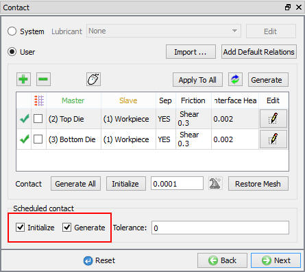
Contact page
Stopping controls
We are forging to a flash thickness of 0.250”. So, check the Distance between objects check box, Select points on the bottom of the Top Die, and the top of the Bottom Die. Enter a stopping distance of 0.250 in Z direction as shown in Fig. L2.4. Click ![]() .
.

Stopping control window page
Step Controls
In Steps page, change the Number of Steps to 50 , set increment to save as 5 and Solution step definition as die displacement of 0.036 in (See Fig. L2.5.), then click ![]() .
.
Step control page
Generating DB
When user visit DB generation page, you can see the objects are positioned with respect to Scheduled positioning data, check if the position of Workpiece is in die cavity is as shown in Fig. L2.6., then check and generate database (See Fig. L2.6.). After generating database, switch to ![]() mode to run the simulation.
mode to run the simulation.
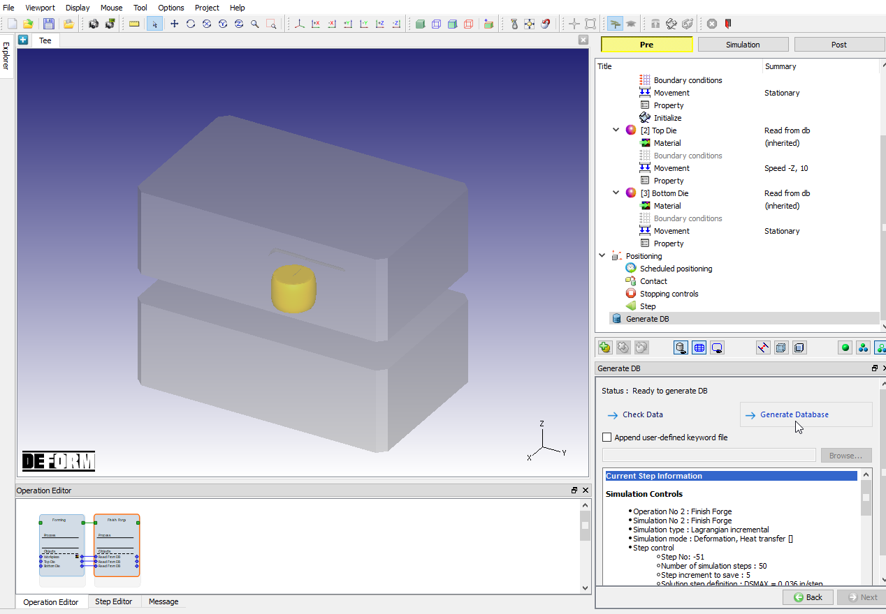
Generate Database page
Running simulation
Click on the ![]() action label to open the Run Options dialog Use the default Continue Run option to select “Continue from the last step ” option and then select the Simulation mode as Interactive and click on
action label to open the Run Options dialog Use the default Continue Run option to select “Continue from the last step ” option and then select the Simulation mode as Interactive and click on ![]() button to run the simulation.
button to run the simulation.
When the simulation is finished without any issues, check the messages in Message file. When operation is completed, we will see a message as
“PROGRAM STOPPED!
THE DISTANCE BETWEEN TWO OBJECTS ( 2 3): 0.2500000 HAS REACHED THE SPECIFIED LIMIT 0.2500000 “.
After completion of simulation, switch to ![]() mode.
mode.
Post processing finishing operation
Right click on the workpiece icon in the process tree and turn on display contact. Watch how the contact evolves as the part fills out die, see Fig. L2.7.
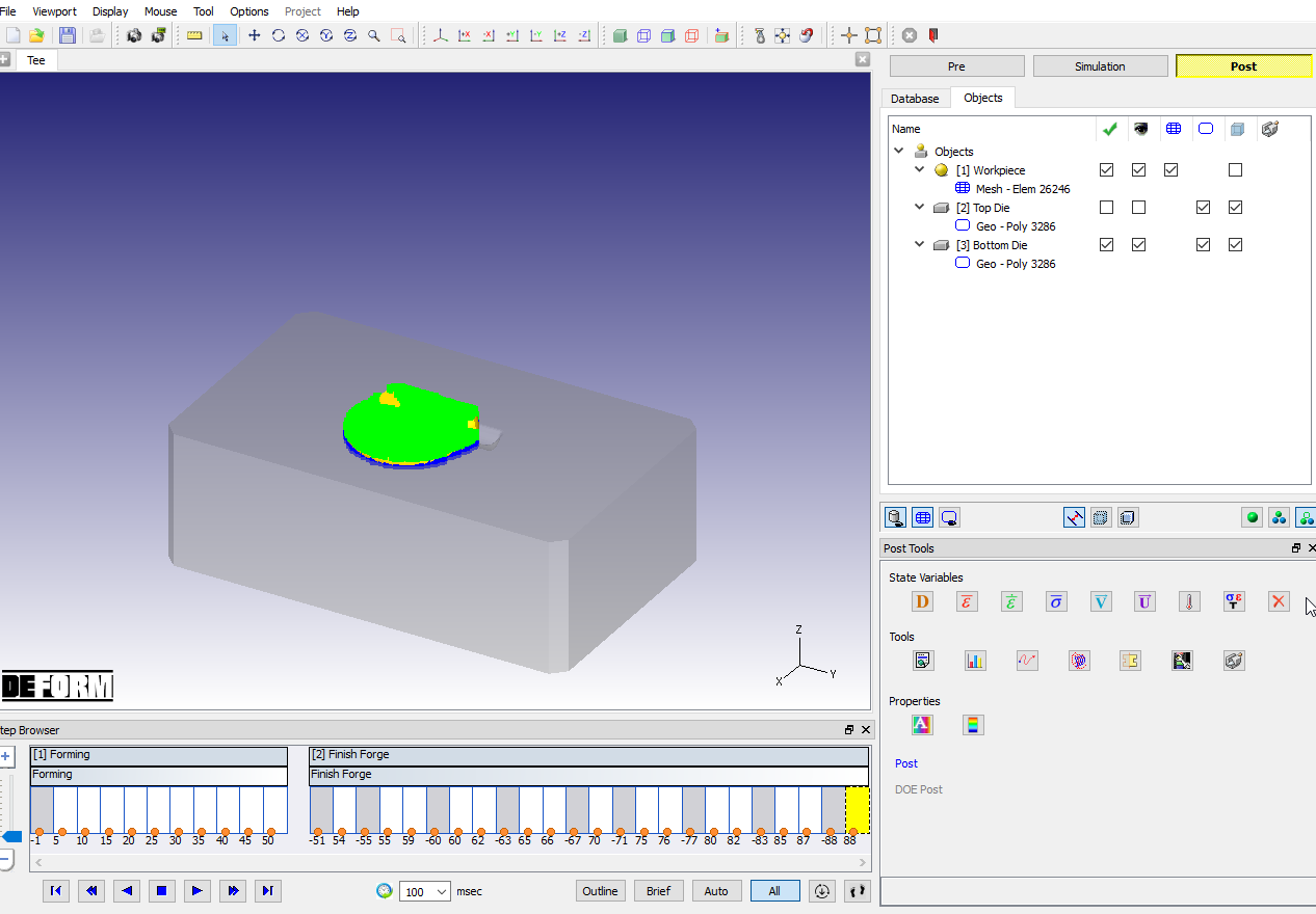
Contact display to check the underfill at last step in Finish Forge operation
Plot the load-stroke curve as shown in Fig. L2.8. Observe how the load increases as the part fills out the die and forms flash.
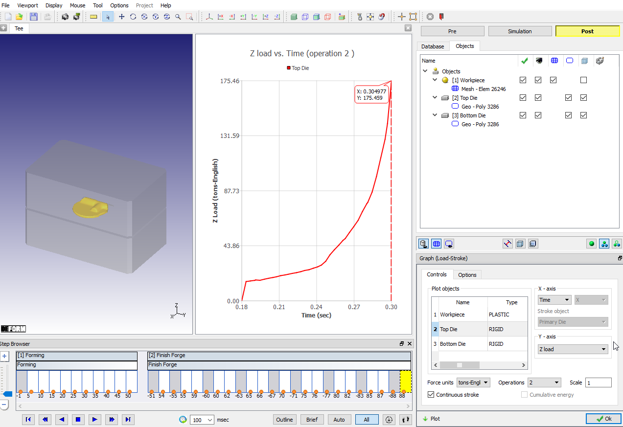
Load-stroke graph plot
Plot the strain rate during forming as shown in Fig. L2.9., observe what happens in the flash area.
Effective Strain rate at the end of Finish Forge operation