Lab 07 Gear Carrier Lab
Introduction
This is the second lab based on an actual industrial part from the 1999 German Forging Industry Association Benchmark. This part will be used to illustrate realistic problem setup. Depending on hardware and system settings, this problem will run from several hours to a day.
The previous lab, Lab04: Steering Link, explained the mesh settings in detail which are used to optimize execution time and problem resolution.
The Process: Mechanical Press Forging
Tooling and Billet Geometry given for 1/12 (300) section
Billet:
Dimensions: 31.5mm dia. x 67mm high
Material: DIN C35
Preheat:1230 C
Tool: Temperature: 80 C
Transfer from furnace: 7 seconds
Dwell on die: 0.7 seconds
First operation: Flat upset to 9.5mm
Transfer to 2nd tool: 3 seconds
Second operation: Forge to shape
Planning the Simulation
This is a two-step forging operation with a relatively long dwell between the furnace and the press. The first operation is straightforward and is not likely to cause difficulties. The second operation is more complex, and results are much more difficult to predict, which makes simulation useful. There are three possible approaches to simulate this process:
-
Simulate the entire process in 3D, including heat transfer, upset, and finisher. This is straightforward to run, and accurately captures temperature and strain distributions in the workpiece.
-
Simulate the upset in 2D, transfer the data to 3D, and simulate the extrude in 3D. The 2D operation is easier to set up and runs very quickly. Translation to 3D requires the use of 2D to 3D conversion utility, which is available with DEFORM ®. Like the entire 3D simulation, this approach accurately captures temperature and strain distributions in the workpiece.
-
Create the upset part geometry in a CAD model and simulate only the second operation. This method is quick, and requires less effort than running the full simulation, but temperature and strain distributions will not be correct, and the discrepancies will affect load calculations, and in some cases may affect material flow behavior.
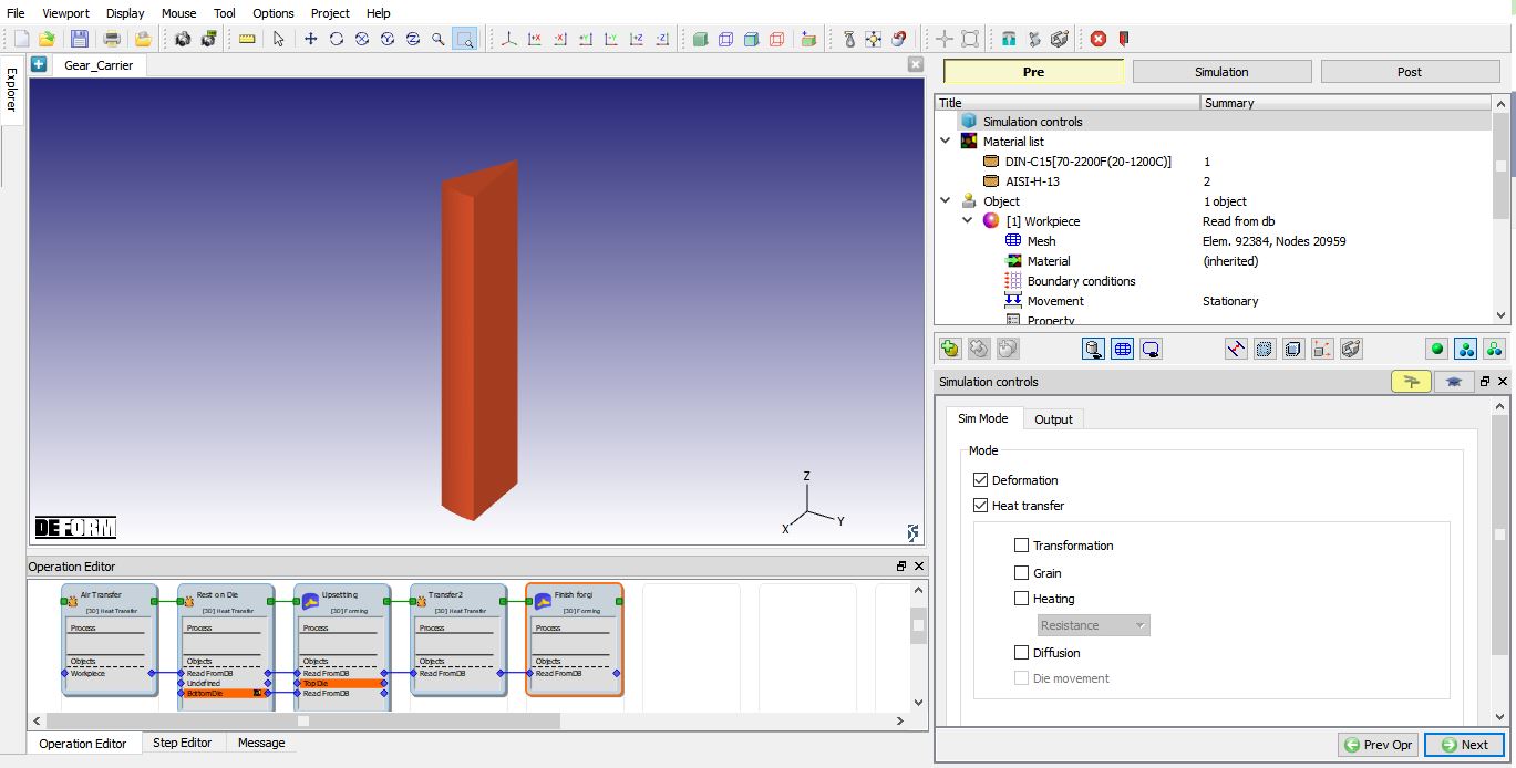
For this problem, we will run the entire simulation in 3D (See Fig. 3DL7.1.). We will set up all operations in batch mode.
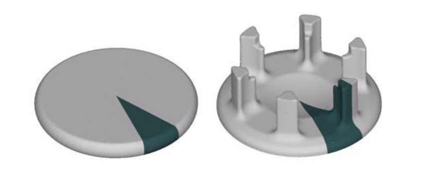
3D CAD model of Upsetting and Finish Forging output
Setting up simulation
Creating New Problem and Adding First Heat transfer operation
On a Windows machine , go to the ![]() button select DEFORM-v1x.xxx (.xxx indicates version number E.g. v14.0.2) and select DEFORM GUI Main vxx.xx from the menu. The DEFORM GUI Main window will appear as shown in Fig. 3DL7.2.
button select DEFORM-v1x.xxx (.xxx indicates version number E.g. v14.0.2) and select DEFORM GUI Main vxx.xx from the menu. The DEFORM GUI Main window will appear as shown in Fig. 3DL7.2.
GUI Main Window
New problem popup
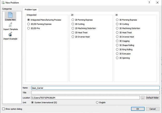
Create a new problem either by selecting File![]() **New Problem** or by clicking the New Problem
**New Problem** or by clicking the New Problem ![]() icon. The Problem Setup window will appear as shown in Fig. 3DL7.3. Select “ Integrated Manufacturing Process” radio button and unit system as “SI “ radio button in Units field. Define Problem Name as “ Gear_Carrier “and make sure the “Show option dialog ” check box is turned on (if we do not turn on the “Show option dialog” check box, then we will not get the New Project dialog). Then click on
icon. The Problem Setup window will appear as shown in Fig. 3DL7.3. Select “ Integrated Manufacturing Process” radio button and unit system as “SI “ radio button in Units field. Define Problem Name as “ Gear_Carrier “and make sure the “Show option dialog ” check box is turned on (if we do not turn on the “Show option dialog” check box, then we will not get the New Project dialog). Then click on ![]() button to open a new problem using the Deform Integrated Manufacturing Process.
button to open a new problem using the Deform Integrated Manufacturing Process.
MO (Multiple operation) template will open, at this point user will be prompted to specify a project name (system will create a separate folder with this project name) and title for this session. In this session, we will use ‘Gear_Carrier ’ as the project name. Select the first operation as 3D Heat transfer operation and turn on the “First operation” checkbox to add Heat transfer operation as first operation. Select the SI Units radio button, click on to open the operation.
Operation1: Air Transfer
In this operation, we setup a heat transfer operation (air stage of the operation) involving transferring of a part for 7 sec from furnace to the forming station. During this time, the part which is at about 2000°F undergoes some cooling in ambient air.
Define Operation Name
Name the operation as “Air Transfer “ by double clicking on Operation name in Operation Editor and press Enter from Keyboard to accept the change as shown in Fig. 3DL7.4.
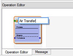
Changing operation name in operation editor.
Defining Heat Transfer Type
Select “Transferthrough air ” as heat transfer type as shown in Fig. 3DL7.5. and click ![]() to continue.
to continue.
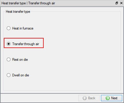
Heat transfer type selection for Air Transfer operation.
Defining Process Conditions
Click ![]() and define the “Transfertime ” as 7 sec with “Environmenttemperature ” as 20 °C and keep default Convection coefficient 0.02 N/sec/mm/C as shown in Fig. 3DL7.6.
and define the “Transfertime ” as 7 sec with “Environmenttemperature ” as 20 °C and keep default Convection coefficient 0.02 N/sec/mm/C as shown in Fig. 3DL7.6.
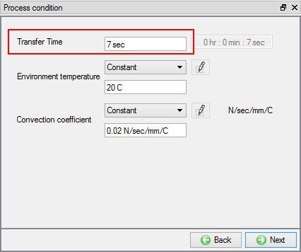
Process Condition settings for Air transfer operation.
Defining Simulation Controls
Keep only Heat Transfer mode checked as shown in Fig. 3DL7.7. as only heat transfer is modelled. User can use expert mode (![]() ) for advanced features, click on
) for advanced features, click on ![]() to continue.
to continue.
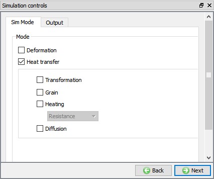
Simulation control page for Air Transfer operation.
Importing material for workpiece
In Material window, load the material ‘DIN-C15[20-2200F(20-1200C)] ‘ from DEFORM Material library, using ![]() (Load material data from library) option. This can be done as shown in Fig. 3DL7.8. Material can also be loaded from Materials list in Explorer. Click on
(Load material data from library) option. This can be done as shown in Fig. 3DL7.8. Material can also be loaded from Materials list in Explorer. Click on ![]() to Objects page.
to Objects page.
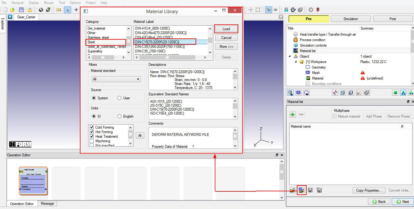
Importing material for Workpiece from DEFORM library.
Defining Workpiece
Defining Workpiece Object settings
In Workpiece object window, keep the object type as ‘Plastic ’ and specify workpiece temperature as 1230 °C (See Fig. 3DL7.9.). Other option available at this stage is ‘Import Object’ from another keyword file or database. Click on ![]() to continue and import the workpiece geometry.
to continue and import the workpiece geometry.
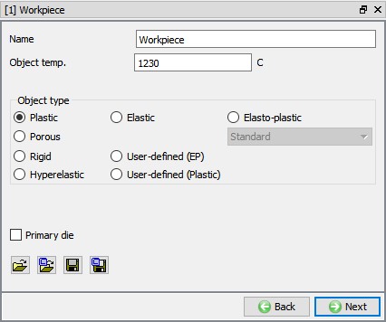
Workpiece object definition.
Importing Workpiece Geometry
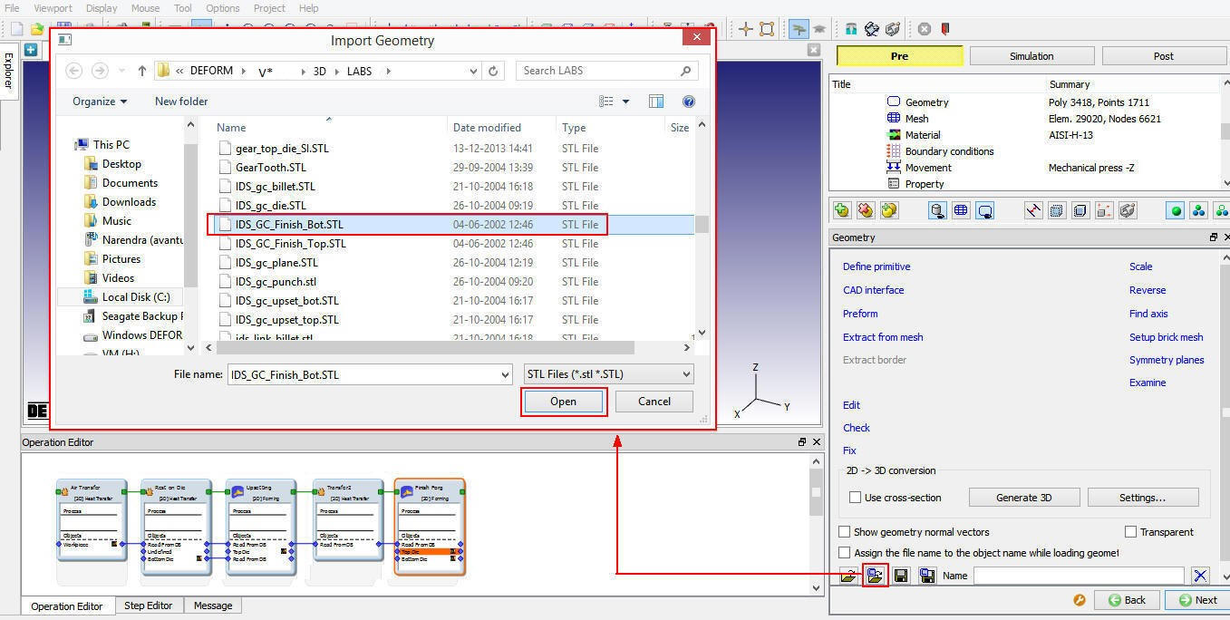
In Geometry page, using ![]() (Load Geometry from Library) button import ‘IDS_GC_Billet.stl ‘ from installation path /3D/LABS/ as shown in Fig. 3DL7.10. Primitive geometry creation option also available at this stage to create the geometry.
(Load Geometry from Library) button import ‘IDS_GC_Billet.stl ‘ from installation path /3D/LABS/ as shown in Fig. 3DL7.10. Primitive geometry creation option also available at this stage to create the geometry.
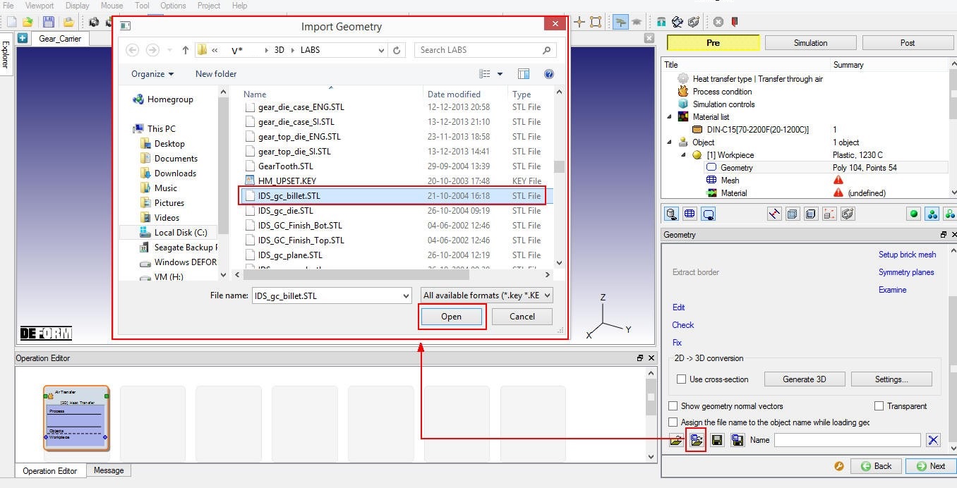
Importing geometry for Workpiece.
After importing any geometry, click on ![]() button to check the geometry, geometry checking window will appear which gives a summary of the object’s geometry (See Fig. 3DL7.11.).
button to check the geometry, geometry checking window will appear which gives a summary of the object’s geometry (See Fig. 3DL7.11.).
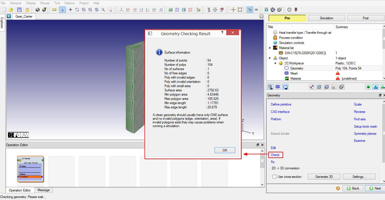
Geometry Check output for Workpiece.
Symmetry planes can be defined using Symmetry Planes label in the geometry page. Click on **![]() ** and select symmetrysurfaces of the billet as shown in Fig. 3DL7.12. The symmetry surface definition will be carried onto BCC, if permitted during mesh generation. Click on
** and select symmetrysurfaces of the billet as shown in Fig. 3DL7.12. The symmetry surface definition will be carried onto BCC, if permitted during mesh generation. Click on ![]() to Mesh page.
to Mesh page.
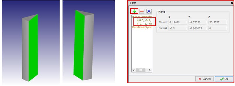
Symmetry planes definition for Workpiece.
Generating Workpiece Mesh
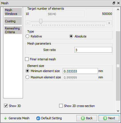
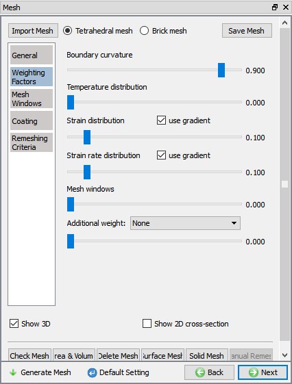
We will generate the mesh by switching to expert mode using ![]() , select absolutemesh , define SizeRatio as 3 and set Minimumelementsize as 0.33 mm (See Fig. 3DL7.13.). Set the Weighting Factors of SurfaceCurvature as0.9, Temperature as 0.0, StrainDistribution as 0.1 and StrainRateDistribution as 0.1 (See Fig. 3DL7.14.). Click on
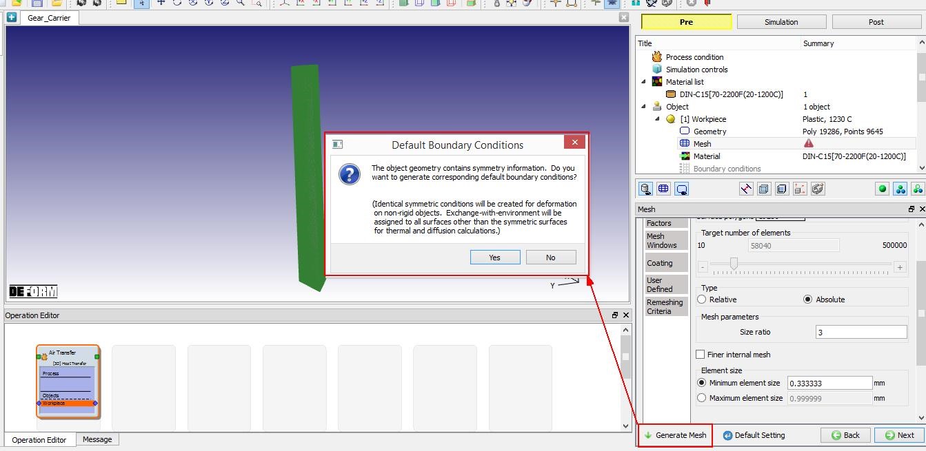
, select absolutemesh , define SizeRatio as 3 and set Minimumelementsize as 0.33 mm (See Fig. 3DL7.13.). Set the Weighting Factors of SurfaceCurvature as0.9, Temperature as 0.0, StrainDistribution as 0.1 and StrainRateDistribution as 0.1 (See Fig. 3DL7.14.). Click on ![]() button to generate mesh. During mesh generation, Default Boundary Conditions pop-up appears as shown in Fig. 3DL7.15. regarding transferring Symmetry conditions from geometry to BCC, click on “Yes ” to transfer symmetry bcc from geometry to mesh. Click on
button to generate mesh. During mesh generation, Default Boundary Conditions pop-up appears as shown in Fig. 3DL7.15. regarding transferring Symmetry conditions from geometry to BCC, click on “Yes ” to transfer symmetry bcc from geometry to mesh. Click on ![]() to switch back to guided mode. After mesh generation is completed (see Fig. 3DL7.16.), click on
to switch back to guided mode. After mesh generation is completed (see Fig. 3DL7.16.), click on ![]() to continue.
to continue.
Workpiece mesh settings.
Mesh Weighing factors settings for Workpiece.
Default Boundary Conditions pop-up during mesh generation.

Mesh generated for Workpiece.
Assigning Workpiece Material
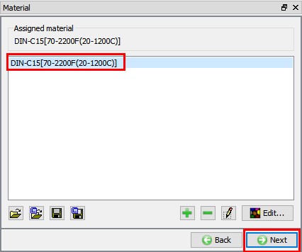
To assign material for workpiece select the material ‘DIN-C15[70-2200F(20-1200C)] ’ from material window, this can be done as shown in Fig. 3DL7.17. Click on ![]() to continue.
to continue.
Assigning material for Workpiece.
Defining workpiece Boundary Conditions
In BCC page, check the defined symmetry planes and default assigned Heat exchange with Environment BCC to the entire outer surface of the Billet except planes as shown in Fig. 3DL7.18. Click on ![]() until Step page.
until Step page.
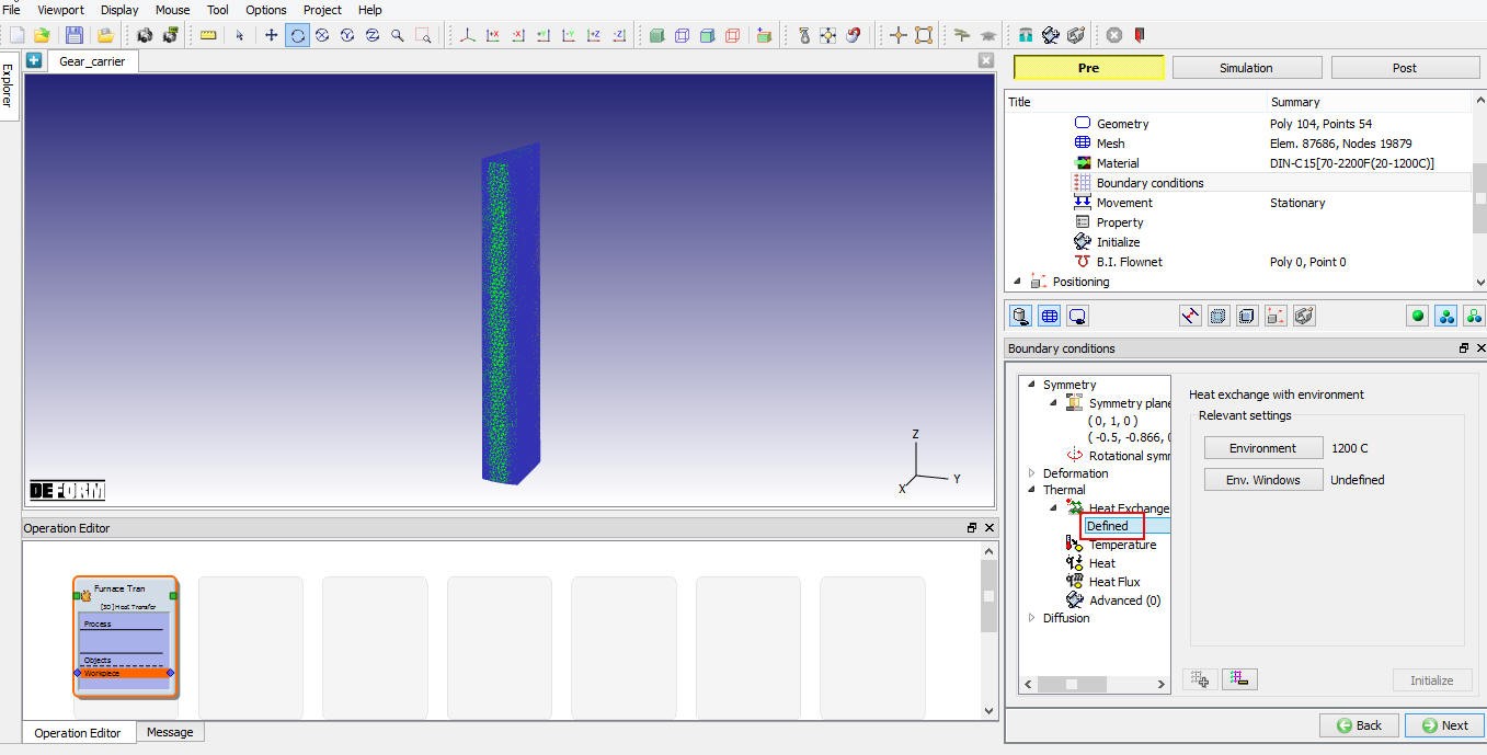
BCC for Workpiece
Defining Step controls
Set thenumber of simulation steps as 14 at 0.5 sec each and saving every 2 steps (See Fig. 3DL7.19.). Advanced Simulation controls settings are available in expert mode (![]() ). Click
). Click ![]() to proceed to the database generation stage.
to proceed to the database generation stage.
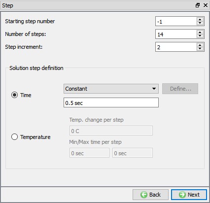
Step control page for Air Transfer operation.
Generating Database
In the database generation stage user can check the data required for the analysis and proceed to generate the database (See Fig. 3DL7.20.). First operation of any multiple operations, user is required to generate the database. For all the subsequent operations we only need to setup the process data and simulation controls.
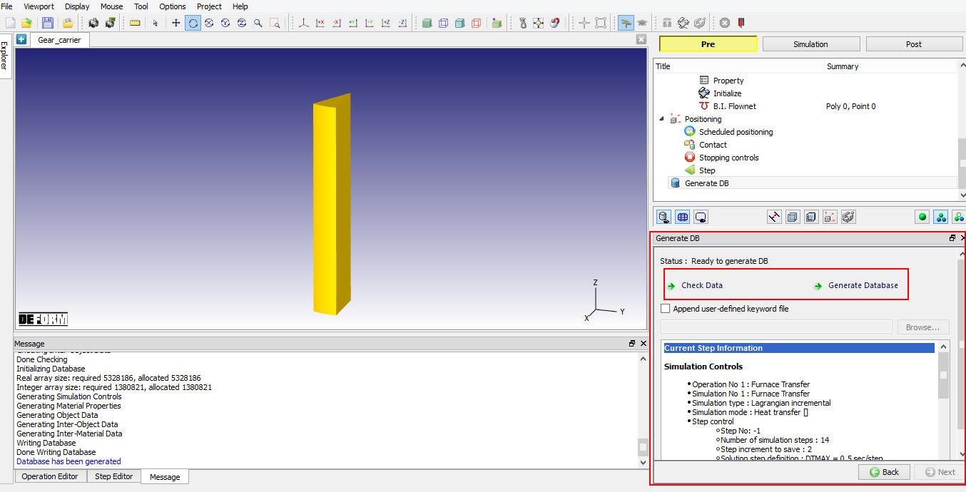
Generating DB for first operation - Air Transfer.
Operation 2: Rest on die
Adding Second Heat Transfer operation
After generating DB of first operation, add another 3D Heat transfer operation by clicking ![]() button as shown in Fig. 3DL7.21. Name the operation as “Rest on Die “ by double clicking on Operation name in Operation Editor and press Enter from Keyboard to close.
button as shown in Fig. 3DL7.21. Name the operation as “Rest on Die “ by double clicking on Operation name in Operation Editor and press Enter from Keyboard to close.
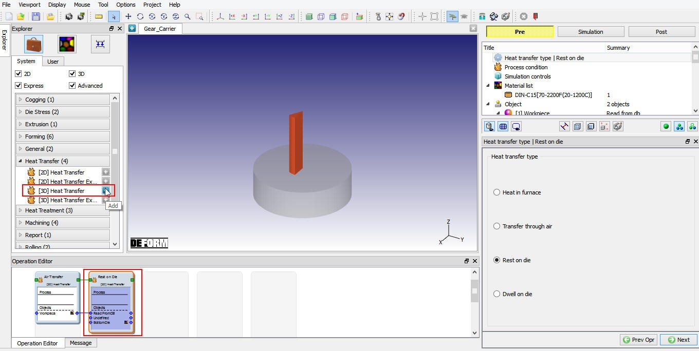
Adding another 3D heat transfer operation to setup Rest on Die operation.
Defining Heat Transfer Type
Select ‘Rest on die ‘ as heat transfer type as shown in Fig. 3DL7.22. and click on ![]() to continue to set up operation.
to continue to set up operation.
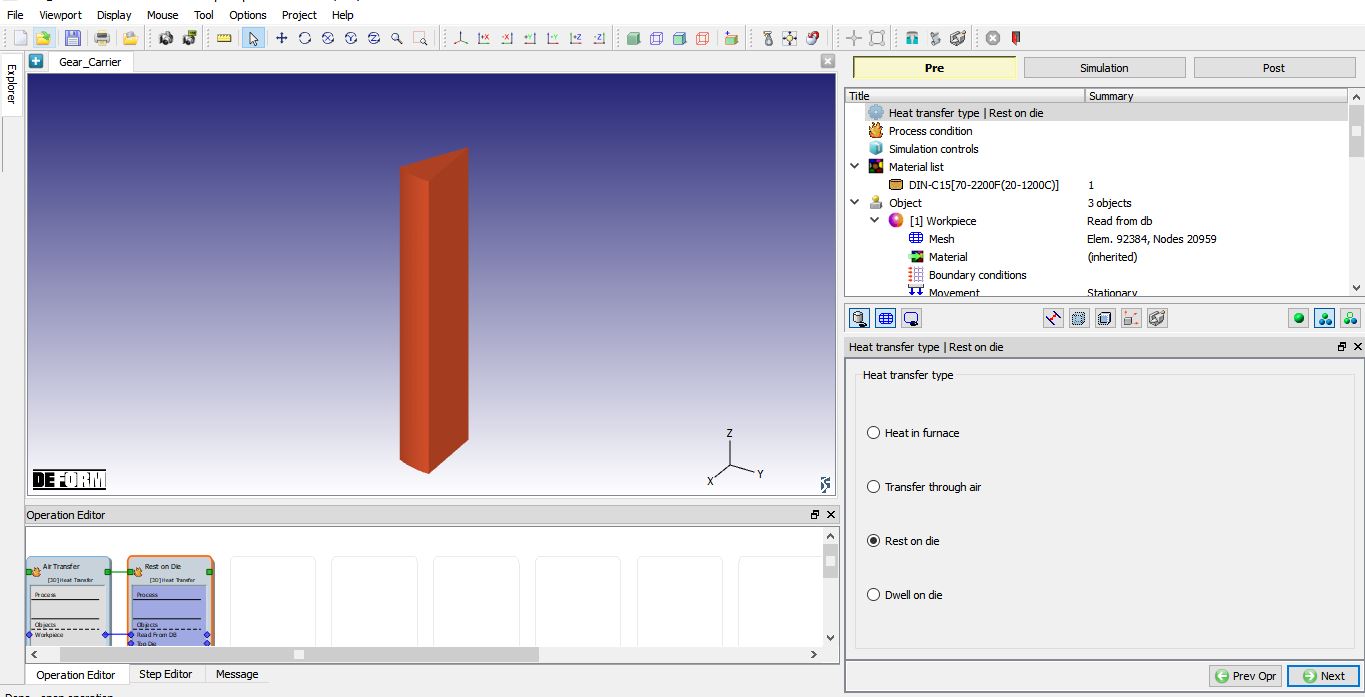
Heat transfer type selection for Rest on die operation.
Defining Process Conditions
Define “Restingtime ” as 0.7 sec with “Environmenttemperature ” as 20 °C and keep default Convectioncoefficient as 0.02 N/sec/mm/C as shown in Fig. 3DL7.23. Click ![]() until Object page in this operation.
until Object page in this operation.
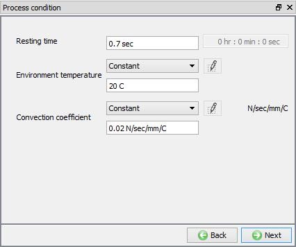
Process Condition settings for Rest on Die operation.
Defining Simulation Controls
Keep only Heat Transfer mode checked as only heat transfer is modelled as shown in Fig. 3DL7.24. and click ![]() to continue.
to continue.
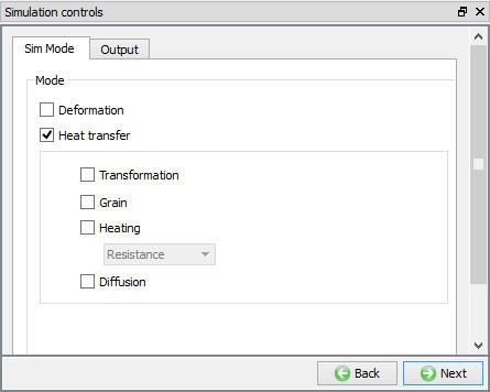
Simulation Controls settings for Rest on die operation.
Add Die Objects
For resting on die operation, we need to have “Bottom**Die** ” object hence delete top die object using as shown in Fig. 3DL7.25. Click ![]() until Workpiece object page.
until Workpiece object page.
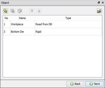
Objects for Rest on Die operation.
Defining Workpiece object type
In Workpiece object page, we will keep the default selection of object type as ‘Readfrom DB’ (See Fig. 3DL7.26.), this indicates that workpiece object data from Air transfer operation will be available as a starting data for this operation. Click ![]() until Bottom die object page.
until Bottom die object page.
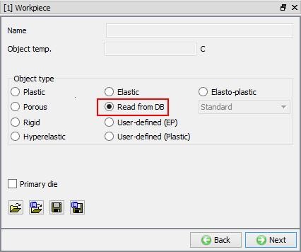
Workpiece object page.
Define Bottom Die
Defining Bottom Die Object settings
In Bottom die object window, keep the object type as ‘Rigid ’ and specify temperature as 80 °C (See Fig. 3DL7.27.). Click on ![]() to continue and import the Bottom die geometry.
to continue and import the Bottom die geometry.

Bottom Die object page.
Importing Bottom Die Geometry
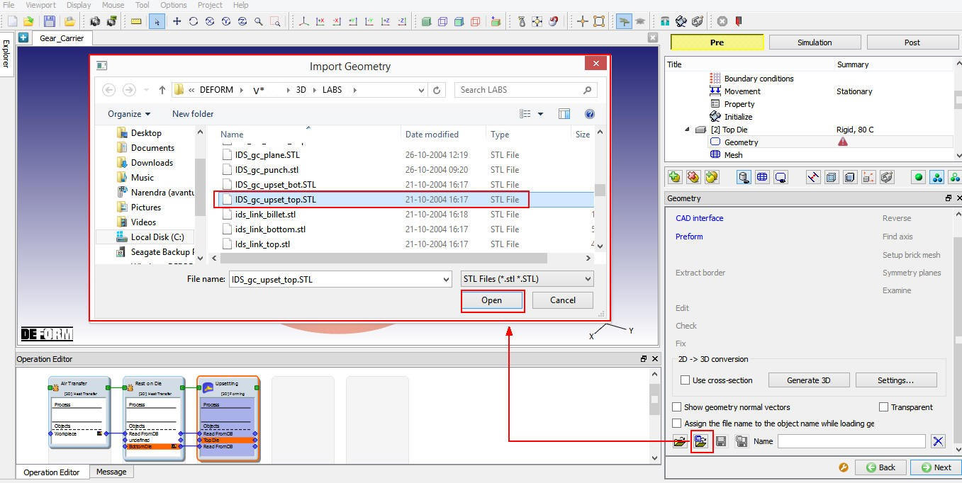
In Geometry page, using ![]() (Load Geometry from Library) button import “IDS_GC_Upset_Bot.stl ” from installation path /3D/LABS/ as shown in Fig. 3DL7.28. Click
(Load Geometry from Library) button import “IDS_GC_Upset_Bot.stl ” from installation path /3D/LABS/ as shown in Fig. 3DL7.28. Click ![]() to Mesh page.
to Mesh page.
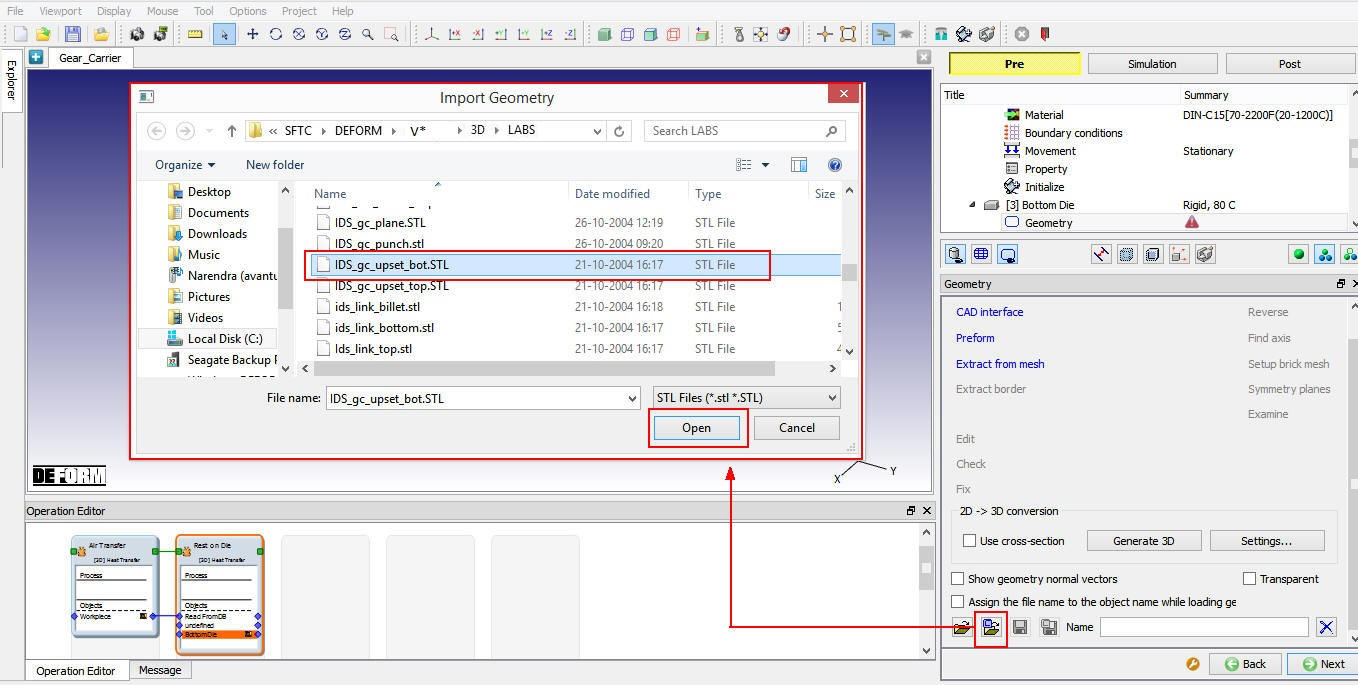
Importing Bottom Die geometry.
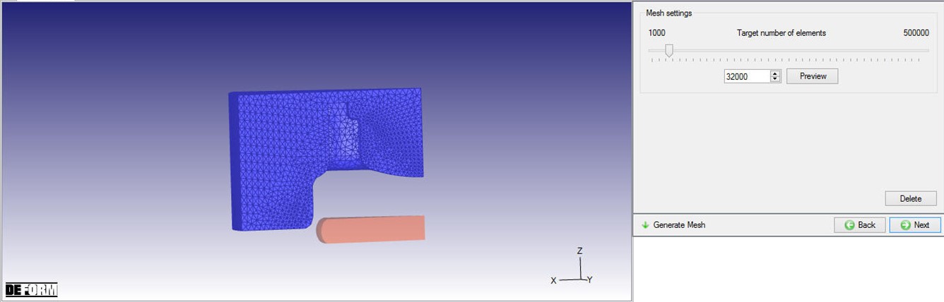
Generating Bottom Die Mesh
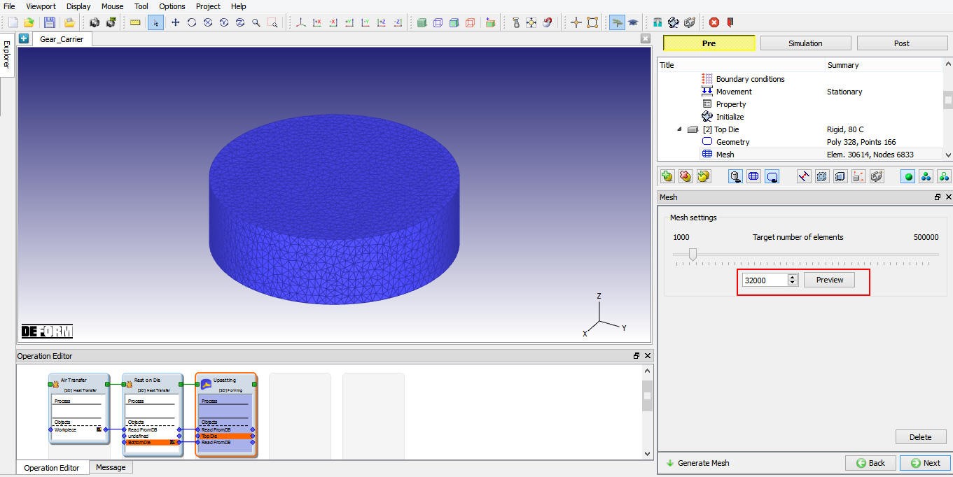
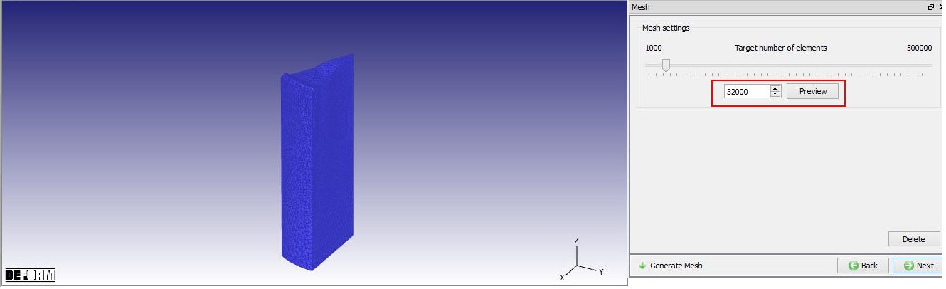
We will generate mesh for Bottom Die using 32000 elements as shown in Fig. 3DL7.29. Click ![]() to Material page.
to Material page.
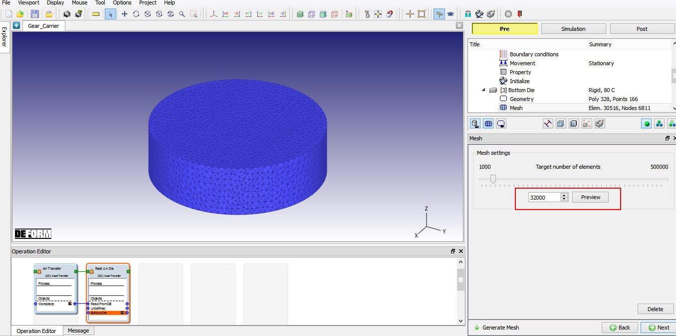
Generating mesh for Bottom Die.
Import Material for Dies
We will load the material AISI-H13 from DEFORM Material library ![]() Die_material category, using
Die_material category, using ![]() (Load material data from library) option as shown in Fig. 3DL7.30. Select the loaded material to assign it to the Bottom Die.
(Load material data from library) option as shown in Fig. 3DL7.30. Select the loaded material to assign it to the Bottom Die.
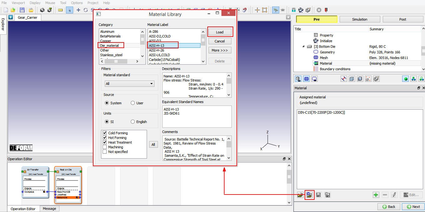
Loading Die material from DEFORM library for Bottom Die.
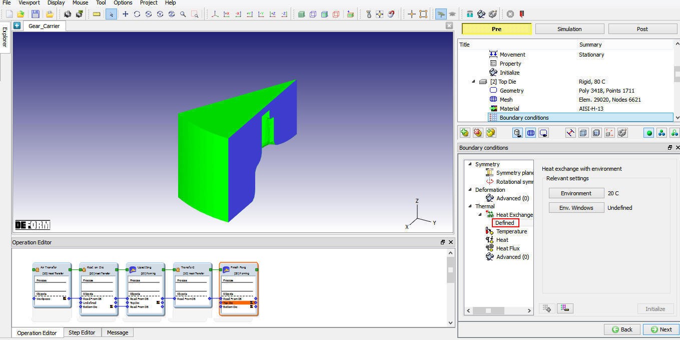
Define Bottom Die BCC
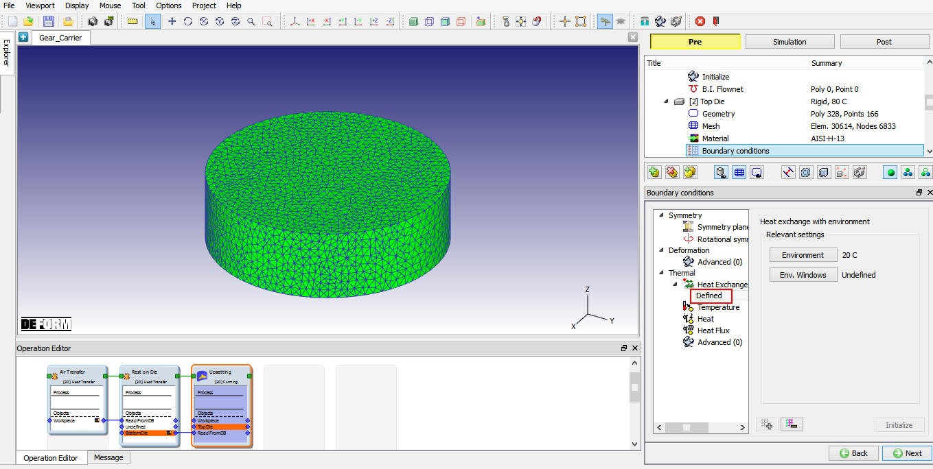
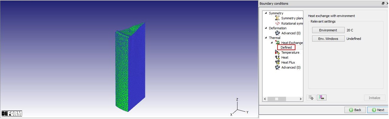
Confirm the automatically assigned Heat Exchange with Environment BCC to all surfaces by clicking on ‘Defined ‘ under Heat exchange with Environment BCC as shown in Fig. 3DL7.31. Click ![]() until Positioning page.
until Positioning page.
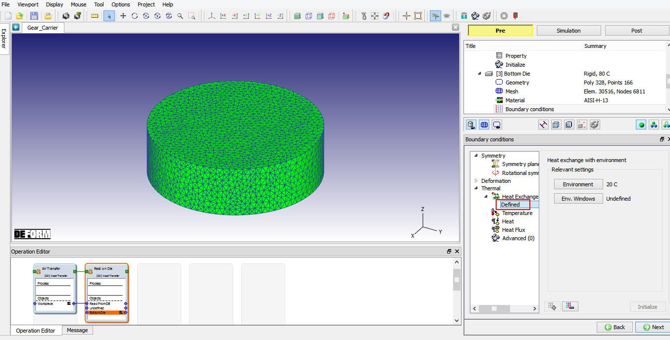
Heat exchange with Environment BCC for Bottom Die.
Schedule Positioning for Bottom die
Define the positioning of Bottom die by clicking on “Schedule**Positioning** ” label and then add action by clicking on ![]() (Add) button, select the ‘Positioningobject ’ as Bottom Die , method as ‘Interference ’ with respect to ‘Workpiece ’ in the Z direction (See Fig. 3DL7.32.). Click
(Add) button, select the ‘Positioningobject ’ as Bottom Die , method as ‘Interference ’ with respect to ‘Workpiece ’ in the Z direction (See Fig. 3DL7.32.). Click ![]() to continue.
to continue.
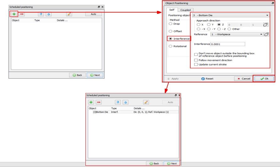
Scheduled positioning for Bottom Die in Rest on Die operation.
Scheduling Contact generation
In Contact page, select Usertype contact and click on ![]() button. Highlight the Bottom Die – Workpiece relationship and click on
button. Highlight the Bottom Die – Workpiece relationship and click on ![]() button to modify the contact conditions (See Fig. 3DL7.33.). In Thermal tab, select “Free Resting “ from the drop-down menu to define inter-object heat transfer coefficient of 1 N/sec/mm/C as shown in Fig. 3DL7.34. Click
button to modify the contact conditions (See Fig. 3DL7.33.). In Thermal tab, select “Free Resting “ from the drop-down menu to define inter-object heat transfer coefficient of 1 N/sec/mm/C as shown in Fig. 3DL7.34. Click ![]() to close the Editing window
to close the Editing window
Make sure Initialize and Generate checkboxes are turned on under Schedule contact (See Fig. 3DL7.33.) so that system would generate the inter-object contact during database generation of second operation. Click ![]() until step controls window.
until step controls window.
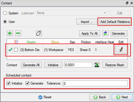
Inter-object contact relationship for Rest on die operation.
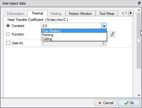
Inter-object contact HTC for Rest on Die operation.
Define Step controls
Set the number of simulation steps as 7 at 0.1 sec each and saving every step (See Fig. 3DL7.35.). Click ![]() to proceed to the database generation stage. Check for any errors in the Database generation page, we will not be generating database as we are setting up second operation in batch mode and database will be generated during runtime after the completion of previous operation simulation.
to proceed to the database generation stage. Check for any errors in the Database generation page, we will not be generating database as we are setting up second operation in batch mode and database will be generated during runtime after the completion of previous operation simulation.
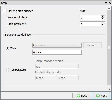
Step Control definition for Rest on Die operation.
Setting up 3rd Operation: Upset operation
Adding first Forming operation
After setting up second operation, we will add first forming operation by clicking on ![]() button as shown in Fig. 3DL7.36. Name the operation as “Upsetting “ by double clicking on Operation name in Operation Editor and press Enter from Keyboard to close.
button as shown in Fig. 3DL7.36. Name the operation as “Upsetting “ by double clicking on Operation name in Operation Editor and press Enter from Keyboard to close.
Adding Forming operation to set up Upsetting operation.
Select Simulation Controls for upsetting
For this operation we need both Deformation and Heat Transfer modes checked as we will be simulating both deformation and heat transfer, see Fig. 3DL7.37. Click ![]() until Object page.
until Object page.

Simulation Controls settings for Upsetting.
Objects for Upsetting operation
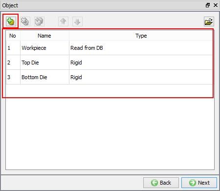
In object page, we can observe that they are three objects. Workpiece and Bottom Die as Read from DB and new Rigid object Top Die is added automatically as object 2 (See Fig. 3DL7.38.). Workpiece and Bottom Die are of “Read from DB” object types, which means object data will be read from the last step of the previous operation simulation.
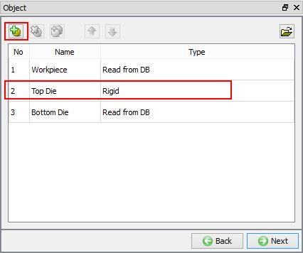
Objects for Upsetting operation.
Defining volume compensation for Workpiece object
Since the Workpiece is of Read from DB object type, we will define only volume compensation related data for it. Click on Workpiece’s Properties in object tree, Properties page will be opened. Turn on “Redefine : Targetvolume ” check box an select Target Volume as Active in FEM + meshing. Click on ![]() to calculate volume of the workpiece, a pop-up appears with information about volume of mesh and geometry, we will use the geometry volume as the target volume, hence click on Yes in the pop-up as shown in Fig. 3DL7.39 and set it as volume to compensate during remeshing. Select Top Die object from object tree.
to calculate volume of the workpiece, a pop-up appears with information about volume of mesh and geometry, we will use the geometry volume as the target volume, hence click on Yes in the pop-up as shown in Fig. 3DL7.39 and set it as volume to compensate during remeshing. Select Top Die object from object tree.
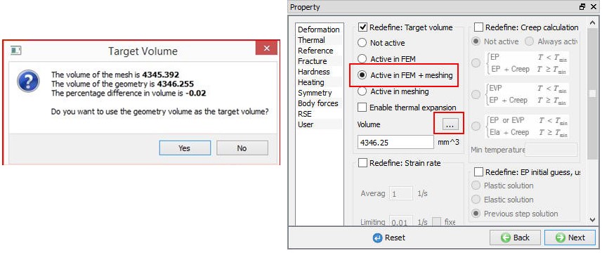
Setting volume compensation for Workpiece.
Defining Top Die
Defining Top Die Object settings
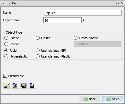
When we select Top Die object from object tree, Top Die object page will be opened. In Top Die object page, keep the object type as ‘Rigid ’ and specify Temperature as 80 °C and turn on “Primarydie ” check box as shown in Fig. 3DL7.40. Click on ![]() to continue and import the Top Die geometry.
to continue and import the Top Die geometry.

Upsetting operation Top die object definition
Importing Top Die Geometry
In Geometry page, using ![]() (Load Geometry from Library) button import ‘IDS_GC_Upset_Top.stl ’ from installation path /3D/LABS/ as shown in Fig. 3DL7.41. Click on
(Load Geometry from Library) button import ‘IDS_GC_Upset_Top.stl ’ from installation path /3D/LABS/ as shown in Fig. 3DL7.41. Click on ![]() button to check the geometry, geometry checking window will appear which gives a summary of the object’s geometry. Click
button to check the geometry, geometry checking window will appear which gives a summary of the object’s geometry. Click ![]() to Mesh page.
to Mesh page.
Importing geometry for Top Die of Upsetting operation.
Generating Mesh for Top Die
We will generate mesh using default 32000 elements as shown in Fig. 3DL7.42. Click ![]() to Material page.
to Material page.
Generating mesh for Top die of Upsetting operation.
Assigning Material for Top Die
Select AISI-H13 material from material list which was already loaded in the previous operation (see 7.4.3.7.4.) to assign it to the Top Die. Click ![]() to BCC page.
to BCC page.
Define Top Die BCC
In ‘Define BCC’ page, we can observe that ‘Heat Exchange with Environment’ BCC is automatically assigned to all surfaces. Click on Defined branch under Heat Exchange with Environment BCC to confirm the BCC definition (See Fig. 3DL7.43.). Click ![]() to Movement page.
to Movement page.
Heat exchange with Environment BCC for Top Die.
Defining Top Die Movement
Select movement type as Mechanicalpress , define Totalstroke as 270 mm, Forgingstroke as 92.5 mm and Cycle/sec as 1.4 (See Fig. 3DL7.44.). Then click ![]() until Positioning page.
until Positioning page.
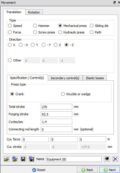
Top die movement definition for Upsetting operation.
Defining Scheduled positioning
We need to position the Top Die over the workpiece, to do so we will use Schedule positioning as the current operation is in batch mode. Click on Schedule positioning link and add action to scheduled position Top Die with respect to Workpiece by interference method in -Z direction as shown in Fig. 3DL7.45. Click on ![]() to Contact page.
to Contact page.
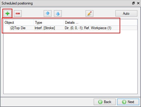
Schedule positioning of Top Die for Upsetting operation.
Scheduling contact generation
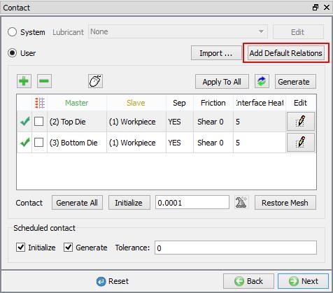
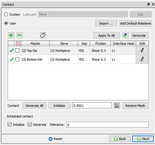
In Contact page, select User type contact and click on ![]() button. It will add the relationship between the Workpiece, Top Die and Bottom Die as shown in Fig. 3DL7.46. Since the Dies are Rigid and Workpiece is plastic, Top Die and Bottom Die are considered as Master and Workpiece as Slave. Make sure Initialize and Generate checkboxes are turned on under Schedule contact (See Fig. 3DL7.46.) so that system would generate the inter-object contact during database generation of second operation.
button. It will add the relationship between the Workpiece, Top Die and Bottom Die as shown in Fig. 3DL7.46. Since the Dies are Rigid and Workpiece is plastic, Top Die and Bottom Die are considered as Master and Workpiece as Slave. Make sure Initialize and Generate checkboxes are turned on under Schedule contact (See Fig. 3DL7.46.) so that system would generate the inter-object contact during database generation of second operation.
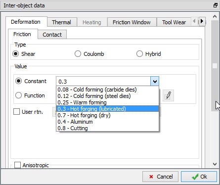
Highlight the Top Die – workpiece relationship and click on ![]() button to modify the contact conditions. In the friction tab, there is a drop-down menu that allows the user to choose the appropriate friction conditions of common forming processes. Since this is hot forming simulation and the dies are steel, use the drop-down menu and select Hot forming (lubricated) from the list (see Fig. 3DL7.47.). A friction value of 0.3 will automatically be selected.
button to modify the contact conditions. In the friction tab, there is a drop-down menu that allows the user to choose the appropriate friction conditions of common forming processes. Since this is hot forming simulation and the dies are steel, use the drop-down menu and select Hot forming (lubricated) from the list (see Fig. 3DL7.47.). A friction value of 0.3 will automatically be selected.
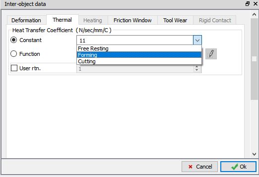
The Thermal data needs to be modified so that a ‘Forming’ heat transfer coefficient is used. Click on Thermal tab and Select Forming in pull down menu as shown in Fig. 3DL7.48.
Inter-Object relationship definition for Upsetting operation.
Inter-object friction coefficient definition window.
Inter-object HTC definition window.
Click ![]() to go back to Contact page, since the friction conditions are the same for all the object pairs,
to go back to Contact page, since the friction conditions are the same for all the object pairs, ![]() button can be used to copy the interface properties from the first relationship to all of the others. After this is done, all relationships will have a friction of 0.3 defined as shown in Fig. 3DL7.49. Since the contact will initialize and generate while generating database. Click
button can be used to copy the interface properties from the first relationship to all of the others. After this is done, all relationships will have a friction of 0.3 defined as shown in Fig. 3DL7.49. Since the contact will initialize and generate while generating database. Click ![]() to Stopping controls page.
to Stopping controls page.
Inter-Object relationship definition for Upsetting operation.
Defining Stopping Controls for upsetting
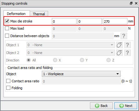
In Stopping controls page, turn on the Max. die stroke stopping control check box and define primary die displacement as (0,0,270) as shown in Fig. 3DL7.50. Advanced stopping options are available in Expert mode (![]() ). Click
). Click ![]() to define the Step controls.
to define the Step controls.
Die stroke stopping control for Upsetting operation.
Define Step Controls for upsetting
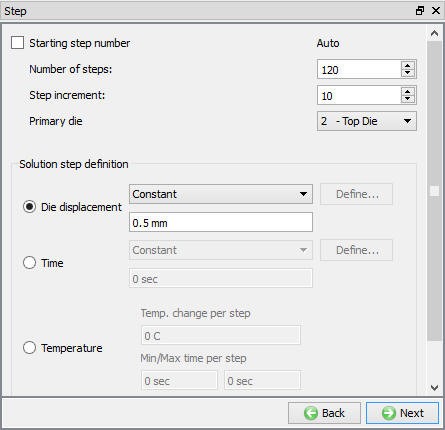
In Step page, define number of steps as 120 at 0.5 mm/step of die movement, step increment to save as 10 for the primary die, make sure Top Die is selected as Primary Die as shown in Fig. 3DL7.51. Click ![]() to DB Generation page, we will not be generating database since the database will be generated during runtime after the completion of previous operation simulation.
to DB Generation page, we will not be generating database since the database will be generated during runtime after the completion of previous operation simulation.
Step controls settings for Upsetting operation.
Setting up 4th Operation: Transfer to second tool
Adding third heat transfer operation
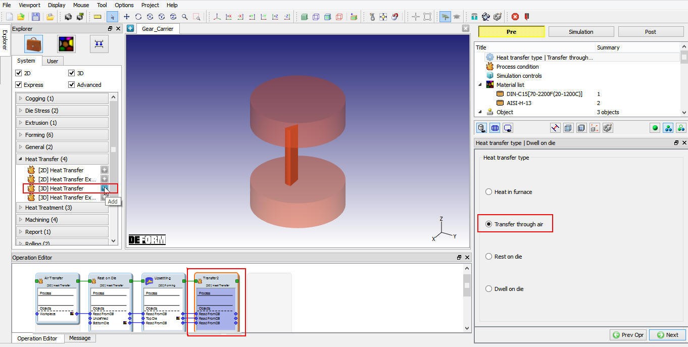
After setting up upsetting operation, add another Heat transfer operation by clicking on ![]() button as shown inn Fig. 3DL7.52. Name the operation as “Transfer 2 “ by double clicking on Operation name in Operation Editor and press Enter from Keyboard to close.
button as shown inn Fig. 3DL7.52. Name the operation as “Transfer 2 “ by double clicking on Operation name in Operation Editor and press Enter from Keyboard to close.
Select Heat Transfer Type
Select ‘Transfer through air ‘ as heat transfer type as shown in Fig. 3DL7.52. and click ![]() to continue.
to continue.
Heat transfer type selection for trransfer to second tool operation.
Set Process Condition for Heat Transfer operation
In Process condition page, define transfer time as 3 sec with 20 °C environment using the default convection coefficient of 0.02 N/sec/mm/C as shown in Fig. 3DL7.53. Click ![]() until Object page.
until Object page.
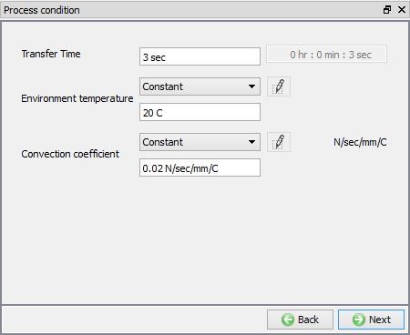
Process condition settings for transfer to second tool operation.
Delete Die Objects
In this operation, we are using transfer through air hence we need to delete both “Top die” and “Bottom Die” objects, Object page should look like as shown in Fig. 3DL7.54. We will keep object type of Workpiece as “Read from DB”, since we need to read object data from the last step of previous simulation as a starting data for this operation. Click ![]() until Step page.
until Step page.
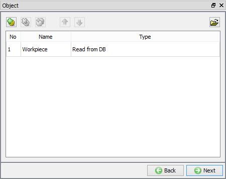
Object page of transfer to second tool.
Defining Step controls
In Step page, define Number of steps as 6, Step increment as 1 and Solution step definition for each step as 0.5 sec. (See Fig. 3DL7.55.). Click ![]() to DB Generation page, we will not be generating database since the database will be generated during runtime after the completion of previous operation simulation.
to DB Generation page, we will not be generating database since the database will be generated during runtime after the completion of previous operation simulation.
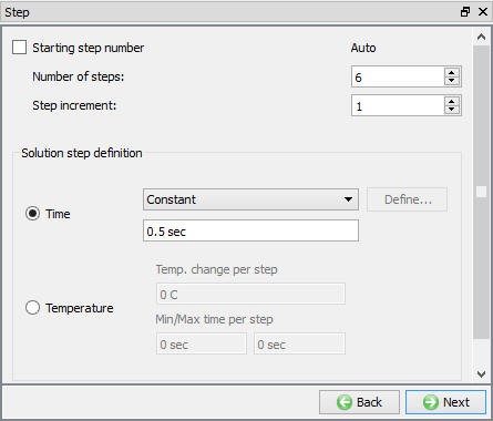
Step controls for transfer to second tool operation.
Setting up 5th Operation: Finish forging
Adding second Forming operation
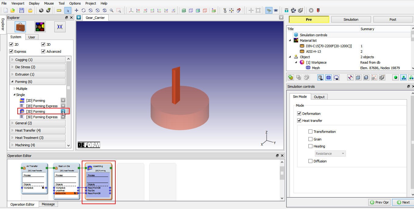
We will add a finish forging operation to the gear carrier lab. From the Explorer tab on the left side of the user interface, go to Forming![]() **Single** and then click the
**Single** and then click the ![]() button next to [3D] Forming as shown in Fig. 3DL7.56. Name the operation as “Finish forging “ by double clicking on Operation name in Operation Editor and press Enter from Keyboard to close.
button next to [3D] Forming as shown in Fig. 3DL7.56. Name the operation as “Finish forging “ by double clicking on Operation name in Operation Editor and press Enter from Keyboard to close.
Adding 3D Forming operation to setup Finish Forging operation.
Select Simulation Controls for Finish operation
In this operation, similar to the Upsetting operation, we will keep both Deformation and Heat Transfer modes checked as shown in Fig. 3DL7.57. Click ![]() until object page.
until object page.

Simulation Controls settings for Finish Forging operation.
Defining objects for Finish forging
In objects page, confirm that three objects are added, and for workpiece object type is set as Read from DB and for Top Die and Bottom Die object type is set as “Rigid ”, See Fig. 3DL7.58. Click on Top Die from object tree.
Object page of Finish forging operation.
Defining Top Die Object
Defining Top Die Object settings
In Top Die object page, keep the object type as ‘Rigid ’ and specify temperature as 80 °C (See Fig. 3DL7.59.). Click on ![]() to continue and import the Top Die geometry.
to continue and import the Top Die geometry.
Finish forging Top die object definition.
Defining Finish forging Top Die Geometry
In Geometry page, using ![]() (Load Geometry from Library) button import ‘IDS_GC_Finish_Top.stl ‘ from installation path /3D/LABS/ as shown in Fig. 3DL7.60. Click on
(Load Geometry from Library) button import ‘IDS_GC_Finish_Top.stl ‘ from installation path /3D/LABS/ as shown in Fig. 3DL7.60. Click on ![]() button to check the geometry, geometry checking window will appear which gives a summary of the object’s geometry.
button to check the geometry, geometry checking window will appear which gives a summary of the object’s geometry.
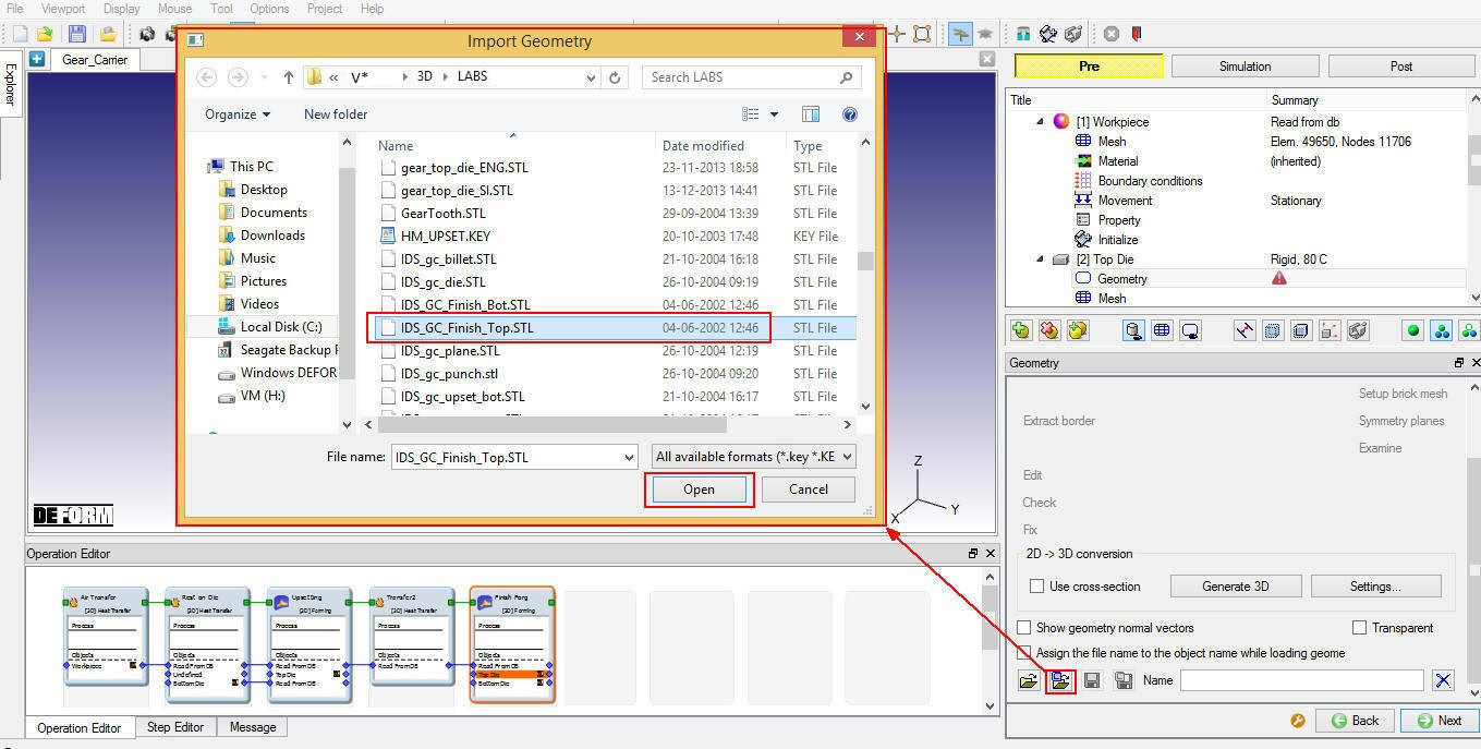
Importing geometry for Finish forging Top Die.
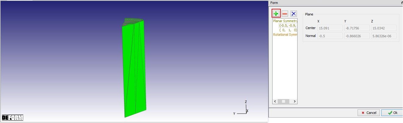
Since the imported geometry is of 1/12 section, we need to define symmetry planes. Symmetry planes can be defined using Symmetry planes label in the geometry page. Click on ![]() and select symmetry surfaces of the Top Die as shown in Fig. 3DL7.61. The symmetry surface definition will be carried onto BCC during mesh generation if permitted during mesh generation. Click on
and select symmetry surfaces of the Top Die as shown in Fig. 3DL7.61. The symmetry surface definition will be carried onto BCC during mesh generation if permitted during mesh generation. Click on ![]() to Mesh page.
to Mesh page.
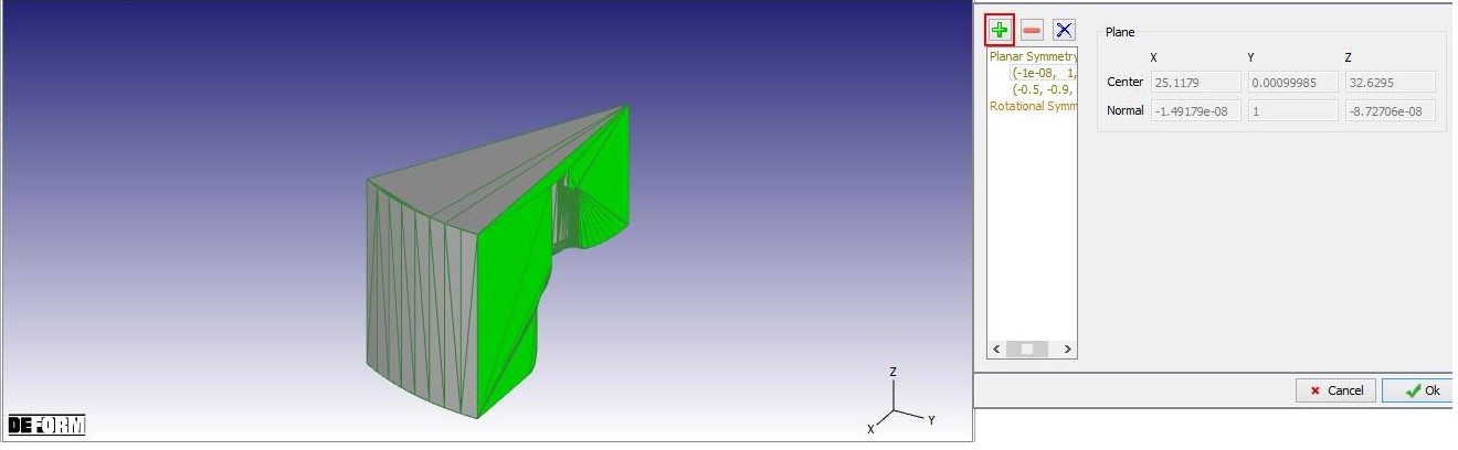
Defining symmetry planes for Finish forging Top Die.
Generate Top Die Mesh
We will generate mesh using default 32000 elements as shown in Fig. 3DL7.62. Click on “Yes ” in “Default Boundary Conditions” pop-up during mesh generation. Click ![]() to Material page.
to Material page.
Generating mesh for Finish forging Top Die.
Assign Material for Top Die
Select AISI-H13 material from material list which was already loaded in the previous operation (see 7.4.3.7.4.) to assign it to the Top Die. Click ![]() to BCC page.
to BCC page.
Defining Top Die Boundary Conditions
In BCC page, check the defined symmetry planes and default assigned Heat exchange with Environment BCC to the entire outer surface of the Top Die except symmetry planes as shown in Fig. 3DL7.63. Click ![]() to define movement.
to define movement.
BCC for Finish forging Top die.
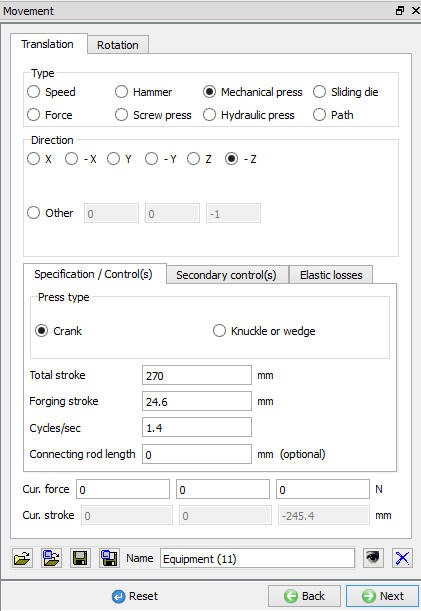
Assigning Top Die Movement
Select Mechanical movement type, define Totalstroke as 270 mm, Forgingstroke as 24.6 mm and Cycle/sec as 1.4 (See Fig. 3DL7.64.). Then click ![]() until Bottom Die page.
until Bottom Die page.
Finish forging Top die movement definition page.
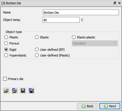
Defining Bottom Die Object type
Defining Bottom Die Object type
In Bottom Die object window keep the object type as ‘Rigid ’ and specify temperature as 80 °C (See Fig. 3DL7.65.). Click on ![]() to continue and import the Bottom die geometry.
to continue and import the Bottom die geometry.
Finish forging Bottom die object page.
Defining Finish forging Bottom Die Geometry
In Geometry page, using ![]() (Load Geometry from Library) button import ‘IDS_GC_Finish_Bot.stl ’ from installation path /3D/LABS/ as shown in Fig. 3DL7.66. Click on
(Load Geometry from Library) button import ‘IDS_GC_Finish_Bot.stl ’ from installation path /3D/LABS/ as shown in Fig. 3DL7.66. Click on ![]() button to check the geometry, geometry checking window will appear which gives a summary of the object’s geometry.
button to check the geometry, geometry checking window will appear which gives a summary of the object’s geometry.
Importing geometry for Finish forging Bottom Die.
Since the imported geometry is of 1/12 section, we need to define symmetry planes. Symmetry planes can be defined using Symmetry planes label in the geometry page. Click on ![]() and select symmetry surfaces of the Bottom Die as shown in Fig. 3DL7.67. The symmetry surface definition will be carried onto BCC during mesh generation if permitted during mesh generation. Click on
and select symmetry surfaces of the Bottom Die as shown in Fig. 3DL7.67. The symmetry surface definition will be carried onto BCC during mesh generation if permitted during mesh generation. Click on ![]() to Mesh page.
to Mesh page.
Defining symmetry planes for Finish forging Bottom Die.
Generate Bottom Die Mesh
We will generate mesh using default 32000 elements as shown in Fig. 3DL7.68. Click on “Yes ” in “Default Boundary Conditions” pop-up during mesh generation. Click ![]() to Material page.
to Material page.
Generating mesh for Finish forging Bottom Die.
Assign Material for Bottom Die
Select AISI-H13 material from material list which was already loaded in the previous operation (see 7.4.3.7.4) to assign it to the Bottom Die. Click ![]() to BCC page.
to BCC page.
Defining Bottom Die Boundary Conditions
In BCC page, check the defined symmetry planes and default assigned Heat exchange with Environment BCC to the entire outer surface of the Bottom Die except symmetry planes, see Fig. 3DL7.69.
BCC for Finish forging Bottom Die.
Defining Scheduled positioning
In Finish forging operation objects are not in correct position, to position the objects properly, we will use Schedule positioning as the current operation is in batch mode. Click on Schedulepositioning link and add action to scheduled position Bottom Die with respect to Workpiece by interference method in + Z direction as shown in Fig. 3DL7.70. Click on ![]() to Contact page.
to Contact page.
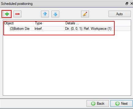
Schedule positioning of Bottom Die in Finish forging operation.
Scheduling contact generation for Finish forging operation
Select user type contact and click on ![]() button. It will add the relationship between the Workpiece, Top Die and Bottom Die (See Fig. 3DL7.71.). As the Dies are Rigid and workpiece is plastic, Top Die and Bottom Die are considered as Master and Workpiece as Slave. Make sure Initialize and Generate checkboxes are turned on under Schedule contact (See Fig. 3DL7.71..) so that system would generate the inter-object contact during database generation of second operation.
button. It will add the relationship between the Workpiece, Top Die and Bottom Die (See Fig. 3DL7.71.). As the Dies are Rigid and workpiece is plastic, Top Die and Bottom Die are considered as Master and Workpiece as Slave. Make sure Initialize and Generate checkboxes are turned on under Schedule contact (See Fig. 3DL7.71..) so that system would generate the inter-object contact during database generation of second operation.
Highlight theTop Die – workpiece relationship and click the ![]() button to modify the contact conditions. In the friction tab, there is a pull-down menu that allows the user to choose the appropriate friction conditions of common forming processes. Since this is hot forming simulation and the dies are steel, use the drop-down menu and select Hot forming (lubricated) from the list. A friction value of 0.3 will automatically be selected.
button to modify the contact conditions. In the friction tab, there is a pull-down menu that allows the user to choose the appropriate friction conditions of common forming processes. Since this is hot forming simulation and the dies are steel, use the drop-down menu and select Hot forming (lubricated) from the list. A friction value of 0.3 will automatically be selected.
Similarly, Thermal data needs to be modified so that a ‘Forming’ heat transfer coefficient is used. Click on Thermal tab and Select Forming in drop-down menu.
Click ![]() to go back to Contact page, since the friction conditions are the same for all the object pairs,
to go back to Contact page, since the friction conditions are the same for all the object pairs, ![]() button can be used to copy the interface properties from the first relationship to all other relations. After this is done, all relationships will have a friction of 0.3 defined as shown in Fig. 3DL7.71. Click
button can be used to copy the interface properties from the first relationship to all other relations. After this is done, all relationships will have a friction of 0.3 defined as shown in Fig. 3DL7.71. Click ![]() to continue.
to continue.
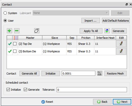
Inter-Object relationship definition of Finish forging operation.
Define stopping control
In Stopping controls page, define Maxload as 1.0e6 N as shown in Fig. 3DL7.72. Click ![]() to Step page.
to Step page.
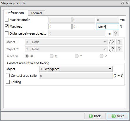
Stopping controls for Finish forging operation.
Defining Step controls
In Step Controls window, define Number of steps as 200 , Stepincrement as 10 and Solutionstepdefinition for each step as 0.5 sec. (See Fig. 3DL7.73.). Click on ![]() to go to Generate DB window.
to go to Generate DB window.
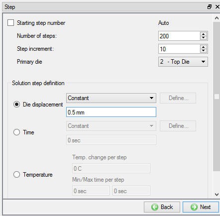
Step control definition for Finish forging operation.
Simulate problem
Start the simulation by clicking the ![]() action label and selecting “Continue Run “ option. (See Fig. 3DL7.74.)
action label and selecting “Continue Run “ option. (See Fig. 3DL7.74.)
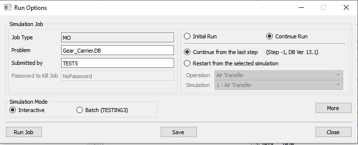
Run Simulation popup window.
Monitor the progress of the simulation by looking at the Simulation Graphics, Simulation Message and Simulation Log tab, make sure that the ![]() option is checked. (See Fig. 3DL7.75.)
option is checked. (See Fig. 3DL7.75.)
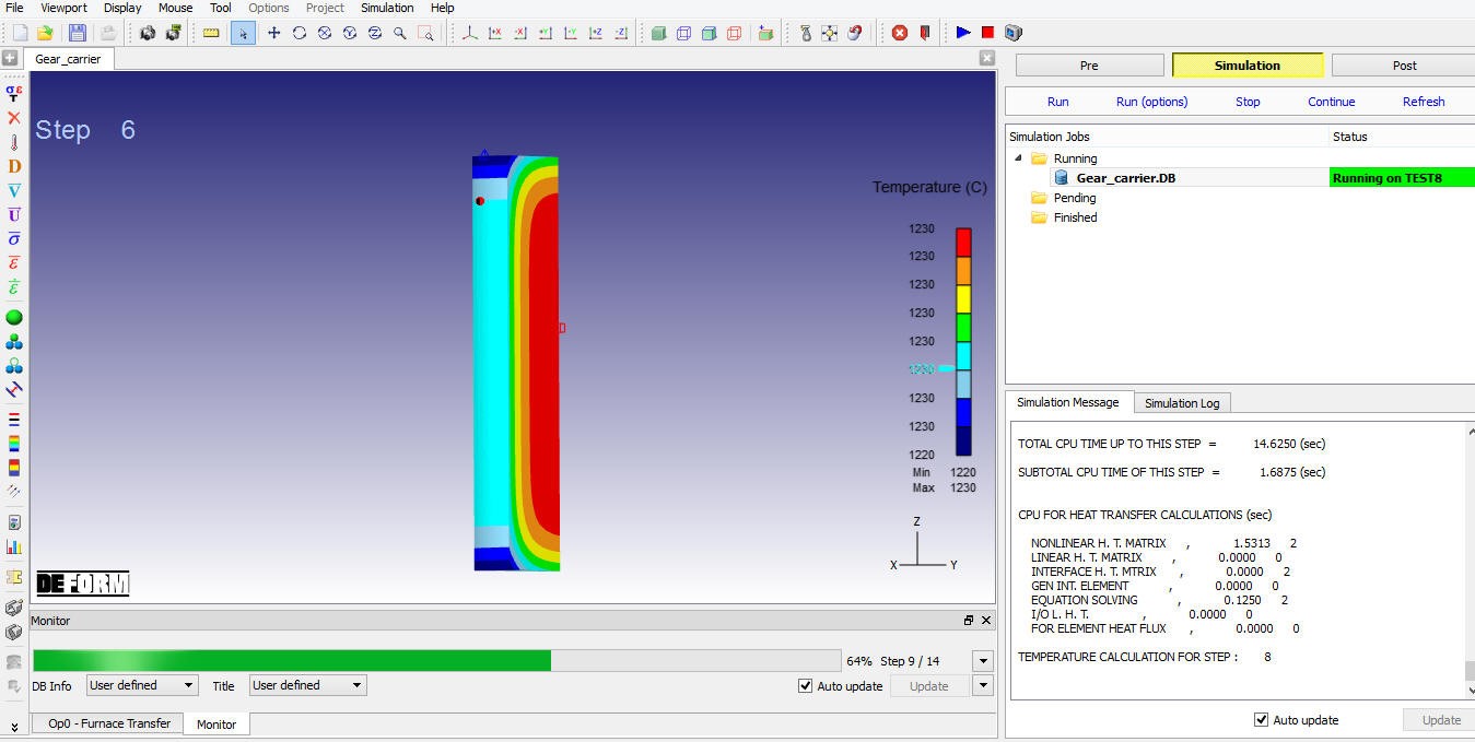
Simulation mode displaying the furnace transfer simulation.
After completion of all multiple operations, in Simulation log file, it gives the log message as “MULTIPLE OPERATION COMPLETED.”, then switch to ![]() tab to view the simulation results.
tab to view the simulation results.
Post Processing
In Post-Processor, plot Temperature state variable and play the steps from first operation to observe the heat transfer in workpiece and dies from Air transfer to second forming operation. Temperature distribution in Workpiece at last step of each operation is as shown in Fig. 3DL7.76.
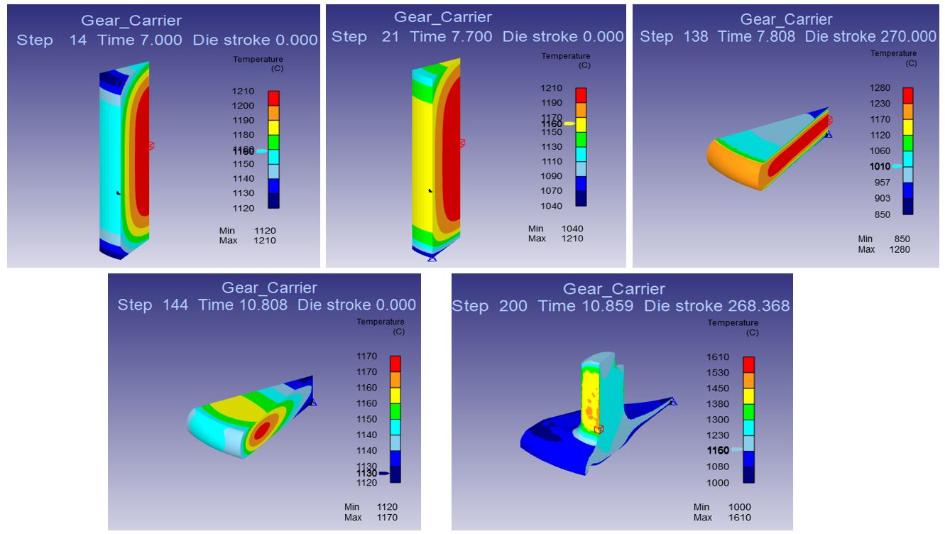
Temperature distribution in Workpiece at last step of each operation from Air transfer to Finish forging operation.
Click on Mirror symmetry ![]() icon and then click on the symmetry faces until you can see the whole part. This will take 11 clicks and the whole part at last step of the simulation will appear as shown in Fig. 3DL7.77.
icon and then click on the symmetry faces until you can see the whole part. This will take 11 clicks and the whole part at last step of the simulation will appear as shown in Fig. 3DL7.77.
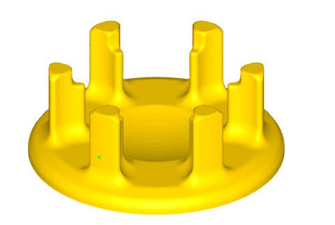
Mirroring of Workpiece symmetric faces in Post-Processor.