ALE Shape Rolling Lab4 (with Multi-stand and using 2.5 D Mesh)
In this lab we will be setting up simple ALE multi-stand rolling operation using Shape Rolling template available in Integrated Manufacturing Process template.
4.1. Creating a New problem
4.2. Adding Shape Rolling operation
4.3. Set process conditions
4.4. Defining Workpiece
4.4.1. Defining Workpiece object
4.4.2. Creating Workpiece Geometry
4.4.3. Generating Workpiece mesh
4.4.4. Assigning Workpiece material
4.4.5. Defining Workpiece boundary conditions
4.5. Defining Grooves
4.5.1. Defining Groove for Roll geometry
4.6. Defining Multi stands in first pass
4.6.1. Running 2.5D Simulation
4.7. Generating 3D Setup
4.7.1. 3D Rolls geometry settings
4.7.2. 3D Rolls mesh settings
4.7.3. 3D Workpiece setup using 2.5D meshing method
4.8. Modifying Rolling pass operation
4.8.1. Modify the Heat Exchange with Environment BCC for Rolls
4.8.2. Defining Contact Relations
4.8.3. Defining Simulation Controls
4.8.4. Generating Database
4.9. Running Simulation
4.10. Post Processing
Creating a New problem
On a Windows machine , go to the ![]() button, select DEFORM-v1x.xxx (.xxx indicates version number E.g. v14.0.2) and select DEFORM GUI Main vxx.xx from the menu. The DEFORM GUI Main window will appear.
button, select DEFORM-v1x.xxx (.xxx indicates version number E.g. v14.0.2) and select DEFORM GUI Main vxx.xx from the menu. The DEFORM GUI Main window will appear.
Create a new problem either by selecting File![]() **New Problem** or by clicking the New Problem
**New Problem** or by clicking the New Problem ![]() icon. The Problem Setup window will appear as shown in Fig. ALEL4.1. Select “ Integrated Manufacturing Process “ radio button and Unit system as “SI “ using radio button. Define Problem Name as “SHR_ALE_LAB4 “ and make sure the “Show option dialog ” check box is turned on (if we do not turn on the “Show option dialog ” check box, then we will not get the New Project dialog in MO UI). Click on
icon. The Problem Setup window will appear as shown in Fig. ALEL4.1. Select “ Integrated Manufacturing Process “ radio button and Unit system as “SI “ using radio button. Define Problem Name as “SHR_ALE_LAB4 “ and make sure the “Show option dialog ” check box is turned on (if we do not turn on the “Show option dialog ” check box, then we will not get the New Project dialog in MO UI). Click on ![]() button to open the new Problem using the Deform Integrated Manufacturing Process.
button to open the new Problem using the Deform Integrated Manufacturing Process.
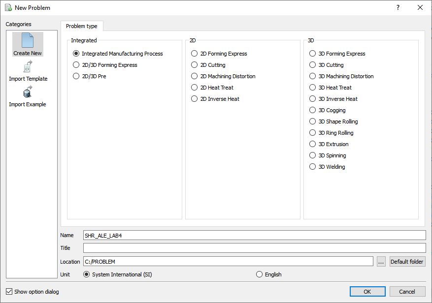
Problem type selection window
Multiple operation wizard will open with the New Project dialog as shown in Fig. ALEL4.2., at this point user will be prompted to specify a project name (system will create a separate folder with this project name) and title for this session. In this session, we will use ‘SHR_ALE_LAB4 ’ as the project name. 3D Shape Rolling operation can also be added in “New Project” dialog (see Fig. ALEL4.2.), but we will add Shape rolling operation from operations list in Explorer in this lab, so do not check “First operation” check box in the “New Project” dialog. Click on ![]() to continue to open the operation.
to continue to open the operation.
Adding Shape Rolling operation
Add one Shape Rolling operation from the Explorer Operations list. Operation can be added by clicking on ![]() button adjacent to Shape Rolling in Explorer or user can also add by drag and drop into the Operation Editor (See Fig. ALEL4.3.). As we add operation, Process page will be opened in the properties area.
button adjacent to Shape Rolling in Explorer or user can also add by drag and drop into the Operation Editor (See Fig. ALEL4.3.). As we add operation, Process page will be opened in the properties area.
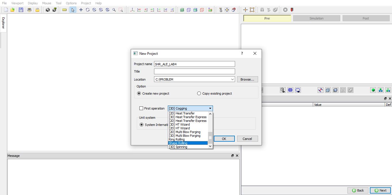
Adding Shape Rolling Operation in MO Wizard from new Project window.
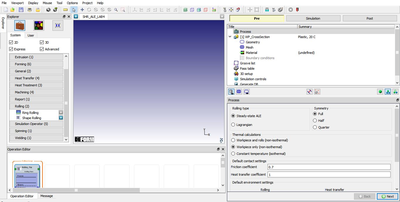
Adding Shape Rolling Operation from explorer.
Set process conditions
In Process page, select the rolling type as “Steady-StateALE ” and symmetry type as “Quarter ”, we will be setting up quarter symmetry object. As we are interested in temperature gradient in rolls, select the “Workpiece and rolls (non-isothermal) “ option.
Change the interface Friction coefficient to 0.5 and interface Heattransfercoefficient to 5(these are global values applicable to all stands and passes) as shown in Fig. ALEL4.4., we will further update the friction conditions in inter-object relations during 3D setup. Click ![]() to WP_CrossSection page.
to WP_CrossSection page.
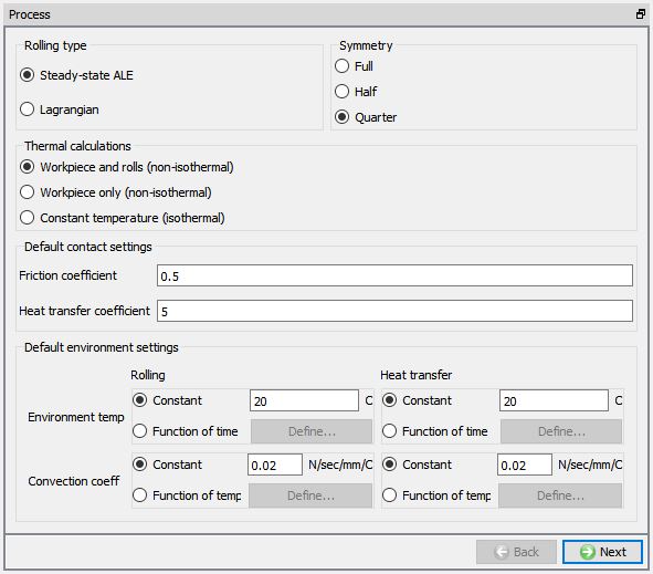
Defining rolling process conditions in Process page.
Defining Workpiece
Defining Workpiece object
In WP_CrossSection window, keep the object type as ‘Plastic ’ and specify workpiece temperature as 100° C (See Fig. ALEL4.5.). Click on ![]() to continue.
to continue.
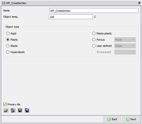
Workpiece Object Definition.
Creating Workpiece Geometry
Since we are setting up a quarter symmetry model, we need to create a 1/4th hollow cylinder geometry for workpiece. To do so, select Define Primitive in Geometry page, select hollow cylinder from primitive geometry window and define the parameters for Centre Point as (0, 0), Radius R1 as 30 mm and Radius R2 as 50 mm as shown in Fig. ALEL4.6. Click ![]() to close. Click
to close. Click ![]() to Mesh.
to Mesh.
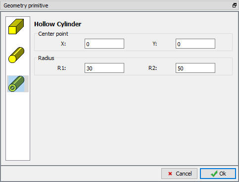
Define Primitive
Generating Workpiece mesh
Generate the workpiece mesh with target number of elements as 100 and keep other options to their default settings (See Fig. ALEL4.7.). If required, expert mode is accessible when we click on ![]() button, to access more settings to control 2D mesh. Click
button, to access more settings to control 2D mesh. Click ![]() .
.
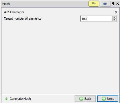
Workpiece mesh generation
Assigning Workpiece material
To assign material for workpiece, select the steel category material ‘AISI-1055 ’ from material library and assign to workpiece. This can be done as shown in Fig. ALEL4.8. Click on ![]() to BCC page.
to BCC page.
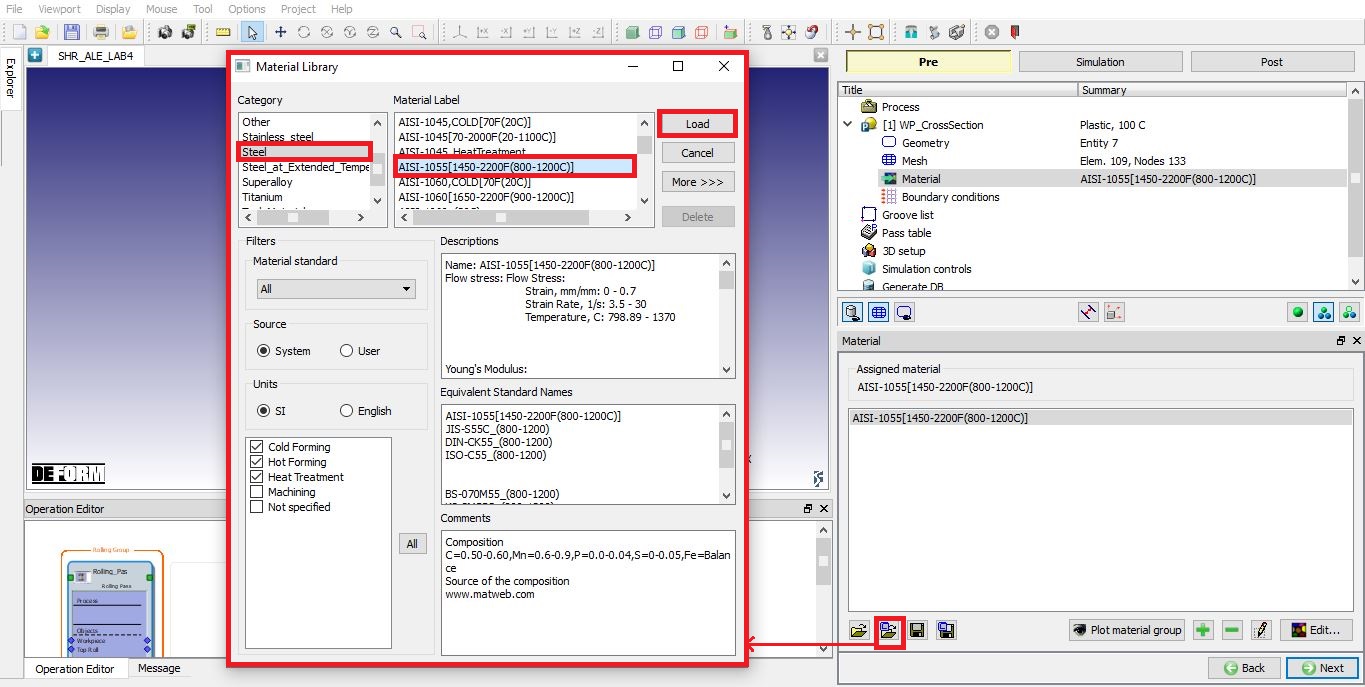
Assigning material for Workpiece.
Defining Workpiece boundary conditions
During the mesh generation the velocity BCC along the symmetry edges are assigned to workpiece as shown in Fig. ALEL4.9. since we had symmetry type as quarter in Process page. Click on ![]() to Groove list page.
to Groove list page.
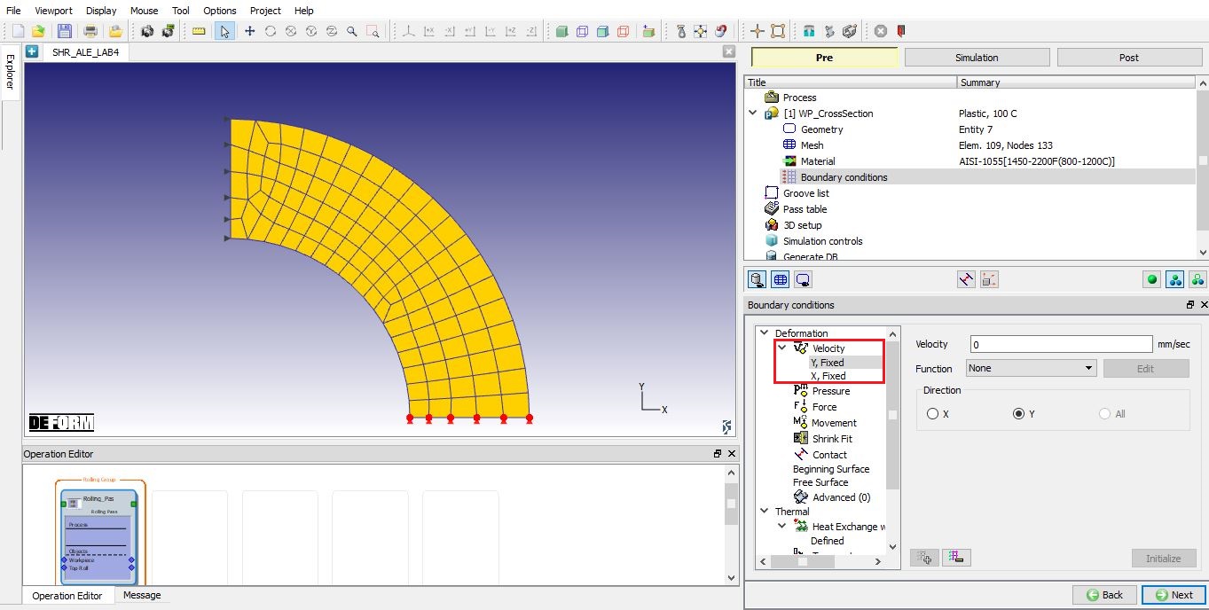
Workpiece boundary conditions page.
Defining Grooves
In Groove List page, we can define rolls 2D cross-section by clicking on the ![]() button. Click
button. Click ![]() once to add one groove (See Fig. ALEL4.10.), we will be using same groove at all roll stands.
once to add one groove (See Fig. ALEL4.10.), we will be using same groove at all roll stands.
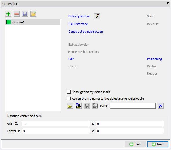
Groove list page.
Defining Groove for Roll geometry
Select the First groove and click on ![]() to select the groove from one of the existing Roll groove primitives.
to select the groove from one of the existing Roll groove primitives.
Roll Groove Primitive page will be opened, select Flat rolls. Define 2D Cross-section geometry of roll grooves with width (W) as 200, radius (r1) as 10 and Roll Radius (RR) as 100 as shown in the Fig. ALEL4.11. Click ![]() to close the Roll Groove Primitive page. Click
to close the Roll Groove Primitive page. Click ![]() to Pass page.
to Pass page.
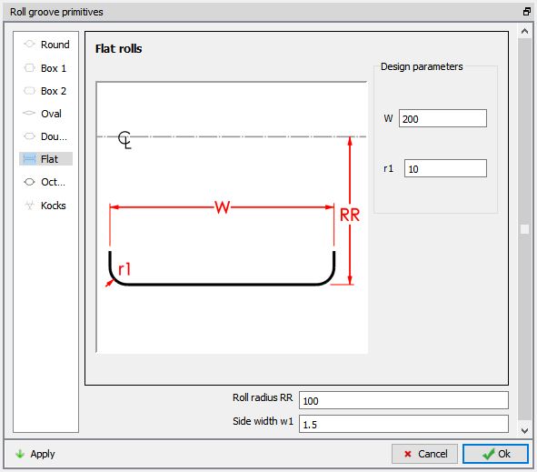
Defining Groove Geometry.
Defining Multi stands in first pass
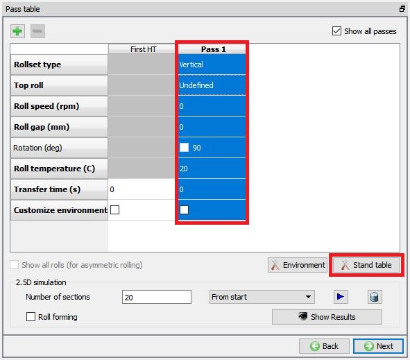
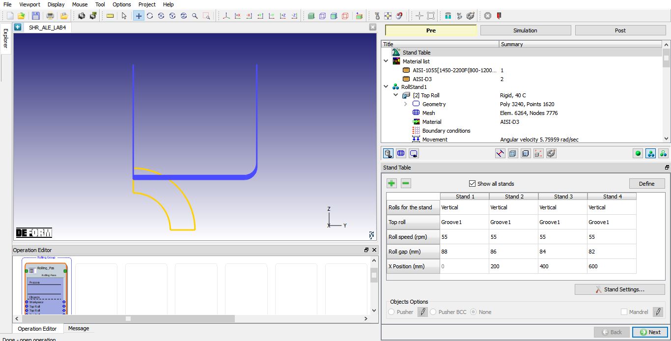
In pass table, select the Pass 1 and click on stand table button as shown in the Fig. ALEL4.12.
In stand table, add 4 stands using the ![]() button. At all four stands, keep
button. At all four stands, keep
-
Rollset type as vertical for all 4 stands.
-
Select Groove1 as groove geometry for Top roll at all four stands.
-
Define Roll speed (rpm) as 55rpm.
-
Set Roll temperature as 40C at all four stands.
Define Roll gap (mm) as 88mm , 86mm , 84mm and 82mm for 1st, 2nd,3 rd and 4th stands and X position as 0, 200, 400 and 600 for 1st, 2nd,3 rd and 4th stands respectively as shown in the Fig. ALEL4.13. Click ![]() to close Stand table settings page and return to Pass table. Leave other settings in Pass table as default and click
to close Stand table settings page and return to Pass table. Leave other settings in Pass table as default and click ![]() to 3D setup page.
to 3D setup page.
Pass Table.
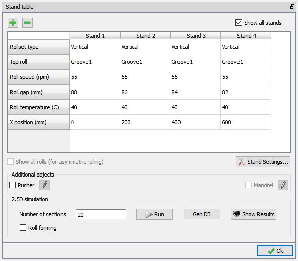
Multi-stand settings defined in Stand Table for first pass.
Running 2.5 D simulation
Click on ![]() button, 2.5D simulation will start to simulate and message file is updated as the simulation progress (see Fig. ALEL4.14.). After completion of simulation click
button, 2.5D simulation will start to simulate and message file is updated as the simulation progress (see Fig. ALEL4.14.). After completion of simulation click ![]() to close.
to close.
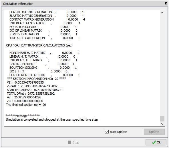
2.5 D Simulation message file.
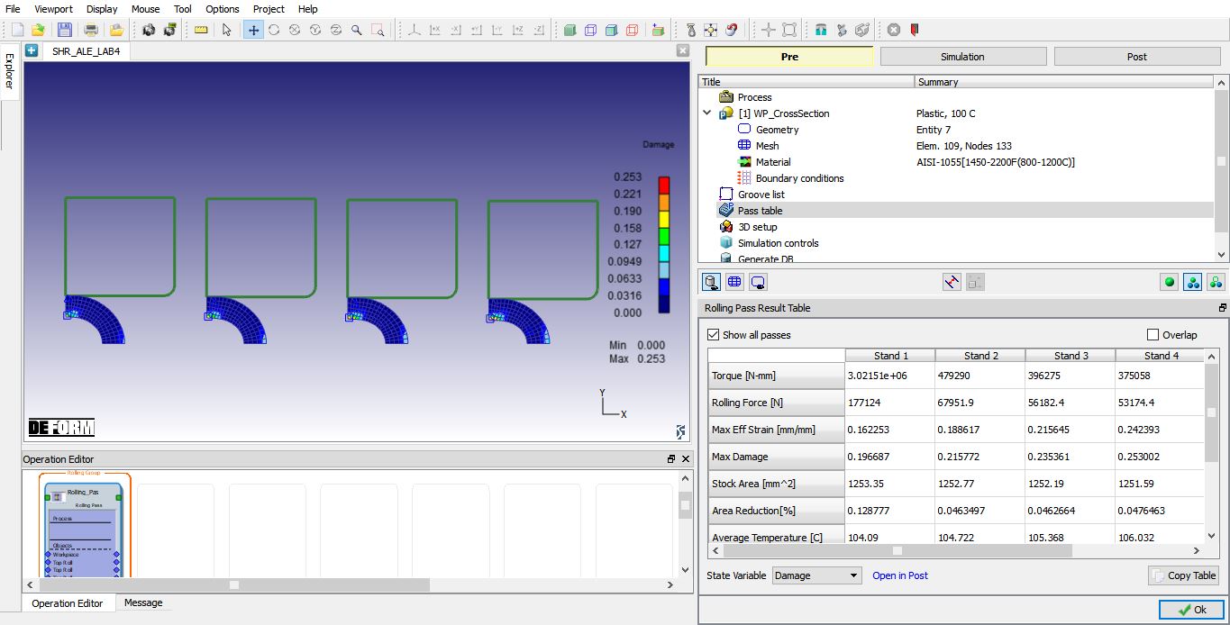
To view the 2.5 D simulation results, click on ![]() button. We will observe the Result table as shown in Fig. ALEL4.15. We can also plot state variables using State variable pull down menu available below the results table and selecting respective state variable. Click
button. We will observe the Result table as shown in Fig. ALEL4.15. We can also plot state variables using State variable pull down menu available below the results table and selecting respective state variable. Click ![]() to close the Results page. User can review results in NG Post using
to close the Results page. User can review results in NG Post using ![]() link below the results table. Click on
link below the results table. Click on ![]() to setup 3D objects for workpiece and Rolls.
to setup 3D objects for workpiece and Rolls.
2.5 D simulation result page
Generating 3D Setup
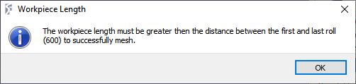
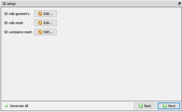
After defining the multi stands by specifying the X position and as we enter the 3D setup page, we will get a Workpiece Length pop-up informing us to define the workpiece length more than the distance between first and last roll (600) as shown in the Fig. ALEL4.16. We will use this information when setting up the Workpiece length in 3D Workpiece settings, click ![]() button for now to close the pop-up. In 3D setup page, we have options to set geometry and mesh settings for Workpiece and 3D Rolls.
button for now to close the pop-up. In 3D setup page, we have options to set geometry and mesh settings for Workpiece and 3D Rolls. ![]() button adjacent to the respective objects can be used to modify the settings, see Fig. ALEL4.17.)
button adjacent to the respective objects can be used to modify the settings, see Fig. ALEL4.17.)
Workpiece length pop-up from 3D setup page.
3D Setup page.
3D Rolls geometry settings
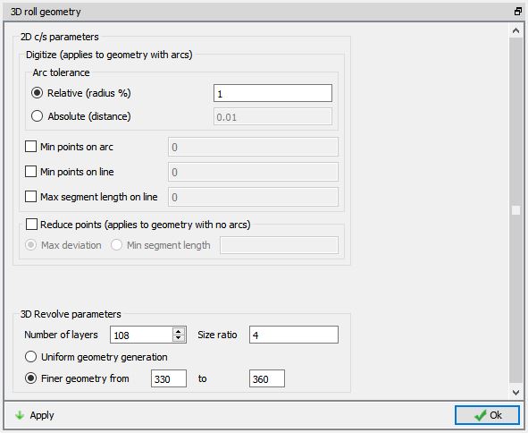
Click on ![]() button of 3D Rolls geometry, 3D roll geometry window will be opened with settings for 3D roll geometry. Define number of layers for rolls as 108 and select the ‘Finer geometry from’ option to generate fine polygons closer to contact region with workpiece, we will set 300° as start and 360° as end angle for finer geometry region as shown in Fig. ALEL4.18. Click on
button of 3D Rolls geometry, 3D roll geometry window will be opened with settings for 3D roll geometry. Define number of layers for rolls as 108 and select the ‘Finer geometry from’ option to generate fine polygons closer to contact region with workpiece, we will set 300° as start and 360° as end angle for finer geometry region as shown in Fig. ALEL4.18. Click on ![]() button to generate rolls with new settings. Click on
button to generate rolls with new settings. Click on ![]() button to close the 3D roll geometry window.
button to close the 3D roll geometry window.
3D Roll Geometry settings page.
3D Rolls mesh settings
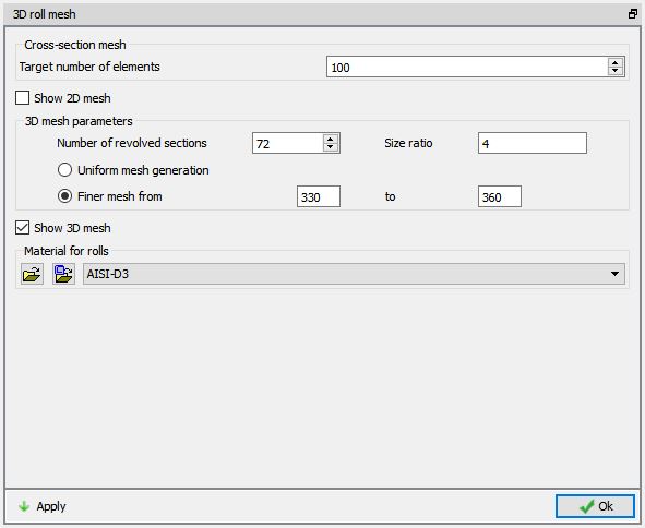
Click on ![]() button of 3D Rolls mesh, 3D roll mesh window will be opened with settings for 3D roll mesh. Define Number of revolved sections for rolls as 72 and select the ‘Finer mesh from’ option to generate fine polygons closer to contact region with workpiece, we will set 330° as start and 360° as end angle for finer mesh region. To assign material for Rolls, load the die material ‘AISI-D3’ from material library and select that material in the pull down menu as shown in Fig. ALEL4.19. Click on
button of 3D Rolls mesh, 3D roll mesh window will be opened with settings for 3D roll mesh. Define Number of revolved sections for rolls as 72 and select the ‘Finer mesh from’ option to generate fine polygons closer to contact region with workpiece, we will set 330° as start and 360° as end angle for finer mesh region. To assign material for Rolls, load the die material ‘AISI-D3’ from material library and select that material in the pull down menu as shown in Fig. ALEL4.19. Click on ![]() button to generate rolls mesh and click on
button to generate rolls mesh and click on ![]() button to close the 3D roll mesh window.
button to close the 3D roll mesh window.
3D Roll mesh settings page
3D Workpiece setup using 2.5D meshing method
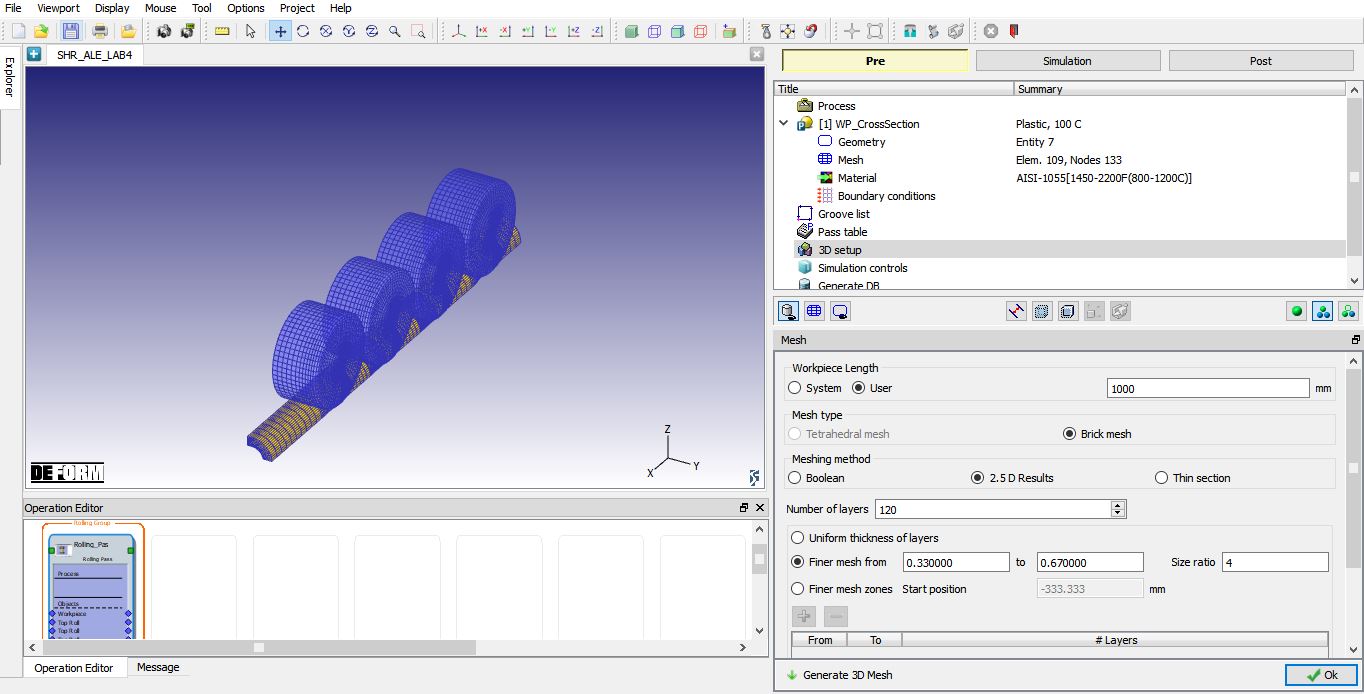
Click on ![]() button of 3D Workpiece, Mesh window with 3D Workpiece mesh settings will be opened. Select user radio button for Workpiece Length and define the length as 1000mm. Select Meshing method as 2**.5 D **Results , define Number of Layers as 120. We will select the ‘Finer geometry from’ option to generate fine polygons closer to contact region with rolls. We will set the finer mesh region from 0.33 to 0.67 (0 as start and 1 as end of workpiece length) as shown in the Fig. ALEL4.20. Click on
button of 3D Workpiece, Mesh window with 3D Workpiece mesh settings will be opened. Select user radio button for Workpiece Length and define the length as 1000mm. Select Meshing method as 2**.5 D **Results , define Number of Layers as 120. We will select the ‘Finer geometry from’ option to generate fine polygons closer to contact region with rolls. We will set the finer mesh region from 0.33 to 0.67 (0 as start and 1 as end of workpiece length) as shown in the Fig. ALEL4.20. Click on ![]() to generate 3D Workpiece mesh. Click
to generate 3D Workpiece mesh. Click ![]() to close the Mesh window of Workpiece. Click on Generate all button to generate 3D Rolls and Workpiece for all stands. Click
to close the Mesh window of Workpiece. Click on Generate all button to generate 3D Rolls and Workpiece for all stands. Click ![]() to continue.
to continue.
3D Workpiece mesh settings page.
Now save the project and select the Rolling Pass operation in operation editor by clicking on the operation tile to modify settings of pass.
Modifying Rolling pass operation
Rolling pass operation.
As you select the Rolling Pass operation, stand table page will appear as shown in Fig. ALEL4.21., it shows all 4-stand data. As we had already defined these settings, click ![]() until RollStand1 Top Roll BCC page.
until RollStand1 Top Roll BCC page.
Modify the Heat Exchange with Environment BCC for Rolls
During mesh generation, a heat exchange with the environment BCC was assigned to the entire roll. The heat exchange with environment BCC must be adjusted to account for the half-symmetric roll geometry. Select the Defined branch under Heat Exchange with Environment and then click the ![]() button from the BCC menu to remove the existing boundary condition. Select all the boundary nodes on the roll except the nodes on the symmetric surface of the roll using the picking tools provided along the left side of the screen. Click the
button from the BCC menu to remove the existing boundary condition. Select all the boundary nodes on the roll except the nodes on the symmetric surface of the roll using the picking tools provided along the left side of the screen. Click the ![]() button from the BCC menu, to add the new boundary condition as shown in the Fig. ALEL4.22. Click on
button from the BCC menu, to add the new boundary condition as shown in the Fig. ALEL4.22. Click on ![]() until Top Roll BCC page of RollStand2.
until Top Roll BCC page of RollStand2.
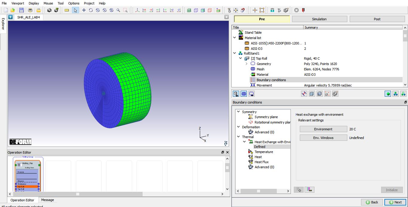
Modified Heat Exchange with Environment BCC for Roll.
Similarly, update the BCC for stand 2, stand 3 and stand 4 rolls. Once the rolls in all stands are updated, click ![]() until Contact page.
until Contact page.
Defining Contact Relations
In the Contact page, master-slave relations will be automatically added between rolls and Workpiece. Select the first relation, define the Coulomb friction as 0.5 and Interface heat transfer coefficient as 5 (See Fig. ALEL4.23.) using ![]() button. Using
button. Using ![]() button, we will apply same frictional conditions between all stands Top Rolls and Workpiece. Click the
button, we will apply same frictional conditions between all stands Top Rolls and Workpiece. Click the ![]() to determine an intelligent contact tolerance and click on the
to determine an intelligent contact tolerance and click on the ![]() button to generate contacts between objects. Click
button to generate contacts between objects. Click ![]() to Simulation controls page.
to Simulation controls page.
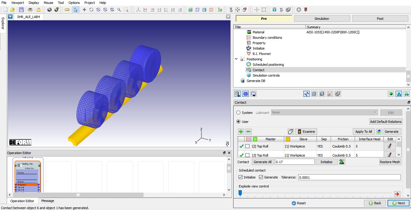
Contact generation.
Defining Simulation Controls
In simulation controls page, set Number of steps as 5000 for this simulation with a step increment to save as 25 and Time per step as 0.001 sec. From DEFORM v12, ALE steady state convergence stopping criteria option has been added in Step controls, user can define ALE steady state Stopping criteria for ALE rolling operation. We will use default values in the lab as shown in Fig. ALEL4.24., click ![]() to generate database.
to generate database.
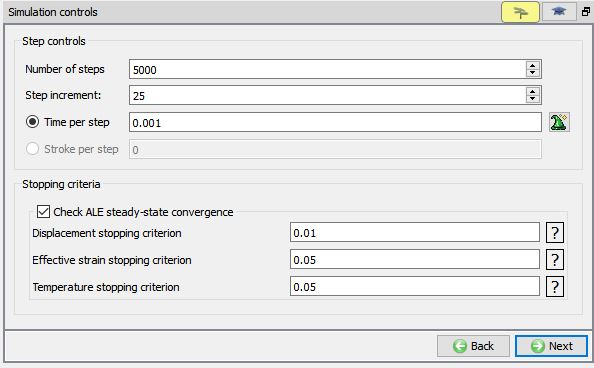
Simulation controls settings.
Generating Database
In the database generation page, user can check the data required for the analysis and proceed to generate the database (See Fig. ALEL4.25.).
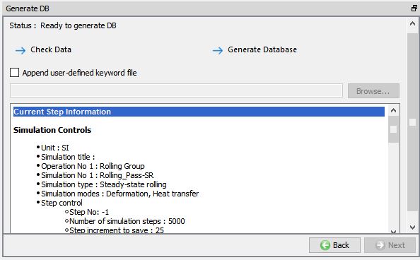
Database Generation.
Running Simulation
Once the database has been generated, switch to the Simulation mode by clicking on ![]() button above the operation tree. Click on the
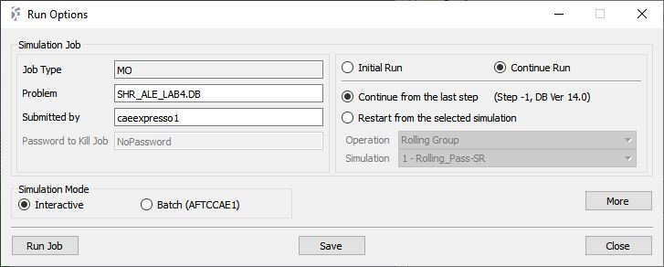
button above the operation tree. Click on the ![]() action label to open the Run Options dialog as shown in Fig. ALEL4.26. Use the default ContinueRun option, select “Continue from the last step ” option and then select the Simulation mode as Interactive radio button. Click on
action label to open the Run Options dialog as shown in Fig. ALEL4.26. Use the default ContinueRun option, select “Continue from the last step ” option and then select the Simulation mode as Interactive radio button. Click on ![]() button to run the simulation.
button to run the simulation.
Click on ![]() button to define MPI settings, Run Options window will expand and displays options to define MPI settings for simulation (max number of processors that can be defined depend on your 3D MPI license).
button to define MPI settings, Run Options window will expand and displays options to define MPI settings for simulation (max number of processors that can be defined depend on your 3D MPI license).
Run Simulation Popup.
Monitor the progress of the simulation by looking at the Simulation Message and Simulation Log tab, make sure that the ![]() option is checked. User can view the rolling process from simulation graphics as the simulation proceeds.
option is checked. User can view the rolling process from simulation graphics as the simulation proceeds.
Simulation will stop after reaching steady state with a below message in Message file.
“
PROGRAM STOPPED!
CURRENT ROLLING PASS HAS REACHED STEADY-STATE CONDITIONS “.
Post Processing
After the simulation has completed, click on ![]() tab, MO post processor will opened as shown in Fig. ALEL4.27.
tab, MO post processor will opened as shown in Fig. ALEL4.27.
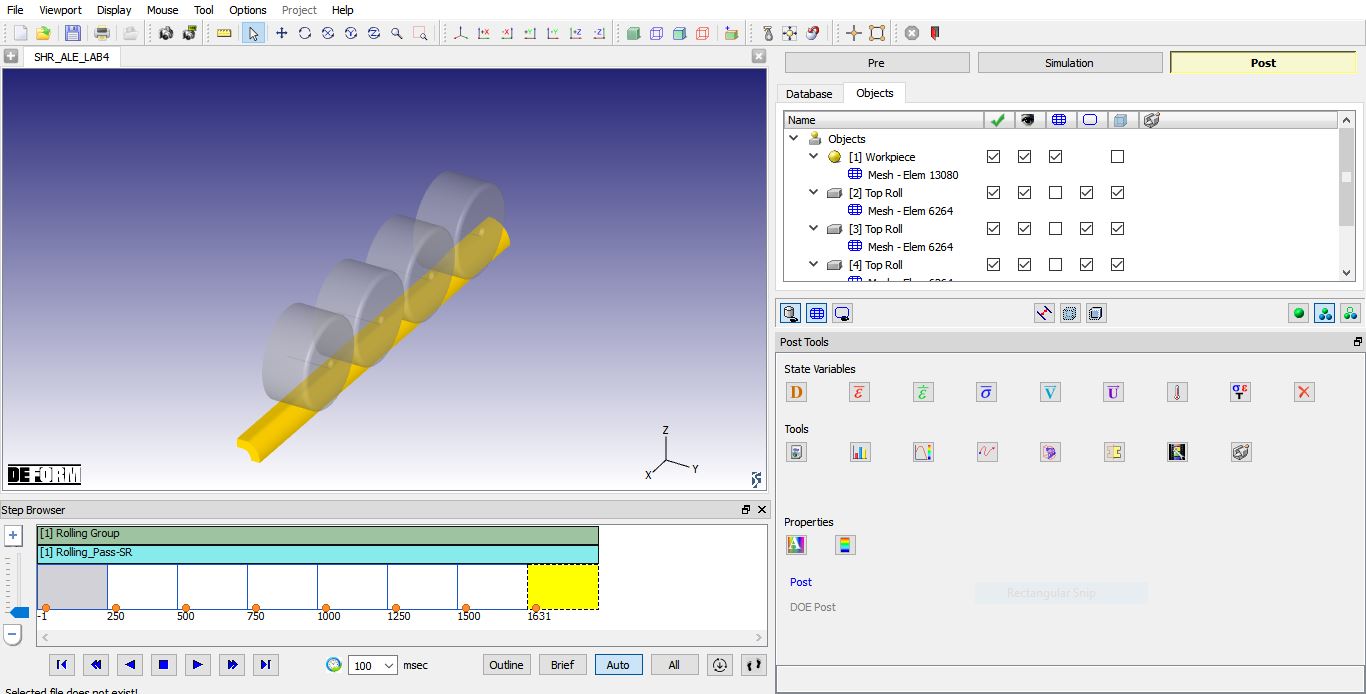
MO Post mode after simulation is completed.
Go to last step, plot Effective strain and Effective stress state variables and observe the state variable distribution.
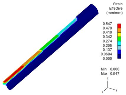
Effective strain distribution at steady-state.
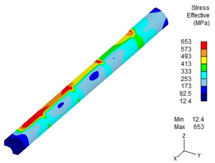
Effective stress distribution at steady-state.