3D Cutting Lab 2
2.1. Summary
2.2. Starting the 3D machining wizard
2.3. Define Machining Process data
2.4. Defining Insert geometry
2.5. Cutting tool positioning
2.6. Assigning Tool Material
2.7. Generating Mesh for Tool
2.8. Workpiece Geometry
2.9. Assigning Workpiece Material
2.10. Generating Mesh for Workpiece
2.11. Workpiece Boundary Condition page
2.12. Tool Positioning
2.13. Tool Wear Setting
2.14. Contact page
2.15. Step Control page
2.16. Generate Database
2.17. Running Simulation
2.18. Post Processing
Summary
In this lab we will demonstrate how to setup turning lab by importing insert geometry in 3D Cutting wizard.
Starting the 3D machining wizard
We can open 3D Cutting wizard in two ways:
a. Create a new problem either by selecting File![]() **New Problem** or by clicking the NewProblem
**New Problem** or by clicking the NewProblem![]() icon. The Problem Setup window will appear. Select “Integrated Manufacturing Process “ radio button and Unit system as “English “ using radio button. Define Problem Name as “ 3D_turning “ and and make sure the “Show option dialog ” check box is turned on (if we do not turn on the “Show option dialog ” check box, then we will not get the New Project dialog in MO UI). Then click on
icon. The Problem Setup window will appear. Select “Integrated Manufacturing Process “ radio button and Unit system as “English “ using radio button. Define Problem Name as “ 3D_turning “ and and make sure the “Show option dialog ” check box is turned on (if we do not turn on the “Show option dialog ” check box, then we will not get the New Project dialog in MO UI). Then click on ![]() button to open a new Problem using the Deform Integrated Manufacturing Process.
button to open a new Problem using the Deform Integrated Manufacturing Process.
Multiple operation wizard will open, at this point user will be prompted to specify a project name (system will create a separate folder with this project name) and title for this session. In this session we will use “3D_turning “ as the project name. Click on ![]() to continue to open the operation. MO wizard will open, add 3D Cutting operation from the Explorer Operations list. Add the operation by clicking on
to continue to open the operation. MO wizard will open, add 3D Cutting operation from the Explorer Operations list. Add the operation by clicking on ![]() button available next to 3D Cutting or by drag and drop into the Operation editor.
button available next to 3D Cutting or by drag and drop into the Operation editor.
b. Create a new problem either by selecting File![]() **New Problem** or by clicking the NewProblem
**New Problem** or by clicking the NewProblem![]() **icon. The Problem Setup window will appear. Select “3D Cutting** “ radio button and Unit system as “English “ using radio button (see Fig. 3DTL2.1.). Define Problem Name as “ 3D_turning “ and click on
**icon. The Problem Setup window will appear. Select “3D Cutting** “ radio button and Unit system as “English “ using radio button (see Fig. 3DTL2.1.). Define Problem Name as “ 3D_turning “ and click on ![]() button to open a new Problem with 3D Cutting operation in MO wizard.
button to open a new Problem with 3D Cutting operation in MO wizard.
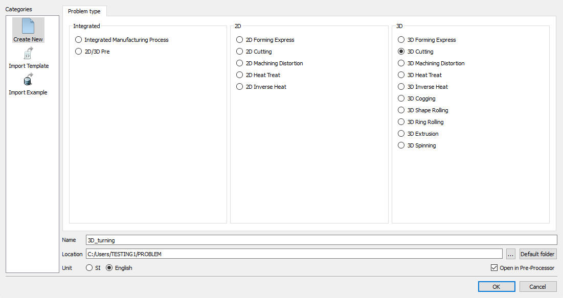
Problem Setup Page
Define Machining Process data
Under the ‘Process ’ menu, Define Cutting type as ‘Turning ‘, enter the Environment Heat Transfer temperature as 68F and use default Convection coefficient 7.7e-06 BTU/sec/in^2/F. Select the Cuttingspeed (v) as 500in/sec , feed rate (f) as 0.012in/rev and Depth of cut (d) as 0.02 in (see Fig. 3DTL2.2.). Alternatively user can also specify rotational speed of the workpiece and part diameter instead of surface speed. Then click on ![]() until Tool page.
until Tool page.
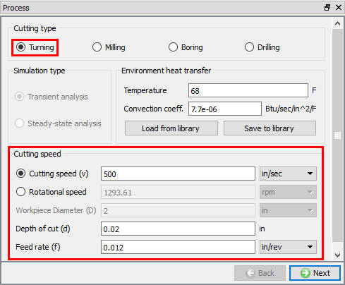
Process page
Defining Insert geometry
In ‘Tool ’ page, enter the tool temperature as 68F. User can import the cutting edge geometry from a previously defined simulation keyword file or a database file using Import Object ![]() option. For this lab we will import cutting edge geometry using the import geometry option. Click
option. For this lab we will import cutting edge geometry using the import geometry option. Click ![]() to import the Insert Geometry. Click on
to import the Insert Geometry. Click on ![]() and import DNMA432 geometry from DEFORM installation \3D\Machining\Insert\EN folder. Select the Cutting Face direction as “Y “, click
and import DNMA432 geometry from DEFORM installation \3D\Machining\Insert\EN folder. Select the Cutting Face direction as “Y “, click ![]() and select the Reference point and click
and select the Reference point and click ![]() . (See Fig. 3DTL2.3.).
. (See Fig. 3DTL2.3.).
In this lab we will position the Cutting tool manually using positioning option. Go to the Controls page by clicking on the “Control “ option in the Operation tree.
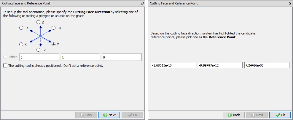
Tool geometry orientation selection page
Cutting tool positioning
We will use a -5 degree face rake and a -5 degree side rake on the tool. Click on ![]() button in the Controls page. In the Object Positioning page select
button in the Controls page. In the Object Positioning page select ![]() position and specify a rotation about the +X axis of “-5 “ degrees. Click
position and specify a rotation about the +X axis of “-5 “ degrees. Click ![]() . Now specify a rotation of “5 “ degrees around the +Z axis and click
. Now specify a rotation of “5 “ degrees around the +Z axis and click ![]() again. Click on
again. Click on ![]() to close the Object Positioning page. Go back to the Tool material page by clicking on the “Tool material” option under Tool in the Operation tree.
to close the Object Positioning page. Go back to the Tool material page by clicking on the “Tool material” option under Tool in the Operation tree.
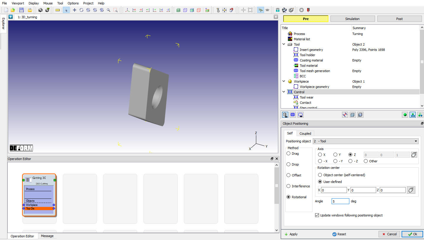
Cutting Tool positioning
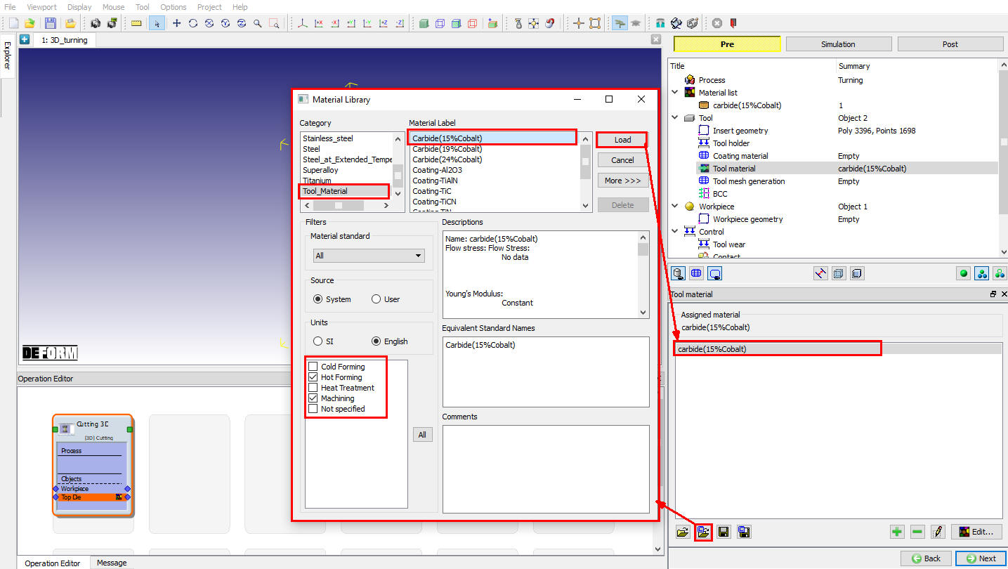
Assigning Tool Material
In the ‘Tool materia l’ page, choose the ‘Load material data from library’ ![]() option, select ‘ToolMaterial ‘ category and ‘Carbide(15% Cobalt) ” (see Fig. 3DTL2.5.). ‘Load’ this material and click
option, select ‘ToolMaterial ‘ category and ‘Carbide(15% Cobalt) ” (see Fig. 3DTL2.5.). ‘Load’ this material and click ![]() to generate Mesh.
to generate Mesh.
Loading Tool material
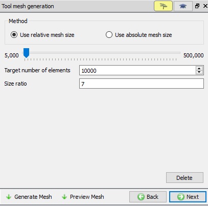
Generating Mesh for Tool
After the tool geometry is generated, generate mesh with Relative mesh type with element sizeratio of 7 and 10000 target number of elements as shown in Fig. 3DTL2.6. Click on ![]() to complete mesh generation for the workpiece. Click
to complete mesh generation for the workpiece. Click ![]() to BCC page. In BCC observe the default Heat exchange BCC assigned for tool and click
to BCC page. In BCC observe the default Heat exchange BCC assigned for tool and click ![]() to Workpiece page.
to Workpiece page.
Generating Tool mesh
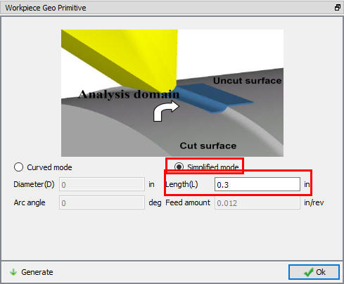
Workpiece Geometry
In the ‘Workpiece’ page define workpiece as a plastic object with a temperature as 68F and click ![]() to proceed. Click on the
to proceed. Click on the ![]() label in the ‘Workpiece geometry’ page. In the ‘Workpiece Geo Primitive’ page specify the workpiece details. Depending upon the workpiece diameter user can specify either a flat model or a curved model. The template will prompt for the related data, and will generate the workpiece setup in the display area. For the current lab select the ‘Simplifiedmode ’ with a length of 0.3 in. Click on
label in the ‘Workpiece geometry’ page. In the ‘Workpiece Geo Primitive’ page specify the workpiece details. Depending upon the workpiece diameter user can specify either a flat model or a curved model. The template will prompt for the related data, and will generate the workpiece setup in the display area. For the current lab select the ‘Simplifiedmode ’ with a length of 0.3 in. Click on ![]() to create the workpiece geometry (see Fig. 3DTL2.7.). Click
to create the workpiece geometry (see Fig. 3DTL2.7.). Click ![]() to close this page and click
to close this page and click ![]() to go to the Object material page.
to go to the Object material page.
Defining Workpiece geometry
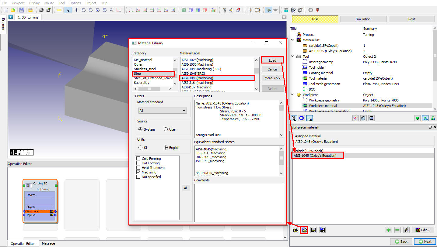
Assigning Workpiece material
In ‘Object Material’ page, choose the ‘Load material data from library’ ![]() option, select ‘Steel ’ category and ‘AISI-1045 (machining) ’ (see Fig. 3DTL2.8.). ‘Load’ this material and click
option, select ‘Steel ’ category and ‘AISI-1045 (machining) ’ (see Fig. 3DTL2.8.). ‘Load’ this material and click ![]() to generate Mesh.
to generate Mesh.
Loading Workpiece material form Library
Generating mesh for Workpiece
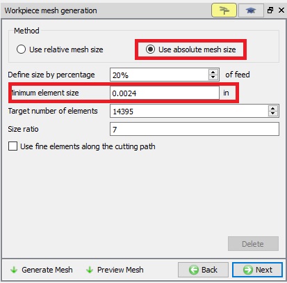
After the work piece geometry is generated, generate mesh with element sizeratio of 7 , and minimum element size of 0.0024 inch.(Fig. 3DTL2.9.). Click on ![]() to complete mesh generation for the workpiece. Click on
to complete mesh generation for the workpiece. Click on ![]() to BCC page.
to BCC page.
Workpiece Mesh page
Workpiece Boundary Condition page
In the ‘View Workpiece BCC’ menu, check the boundary conditions imposed on workpiece by the system (see Fig. 3DTL2.10.), and click ![]() to Controls page. Note the velocity BCC assigned to the bottom surfaces away from the cutting surfaces to prevent workpiece from flying. Heat Exchange with BCC is assigned to all surfaces and temperature BCC is assigned for all surfaces except cutting surfaces.
to Controls page. Note the velocity BCC assigned to the bottom surfaces away from the cutting surfaces to prevent workpiece from flying. Heat Exchange with BCC is assigned to all surfaces and temperature BCC is assigned for all surfaces except cutting surfaces.
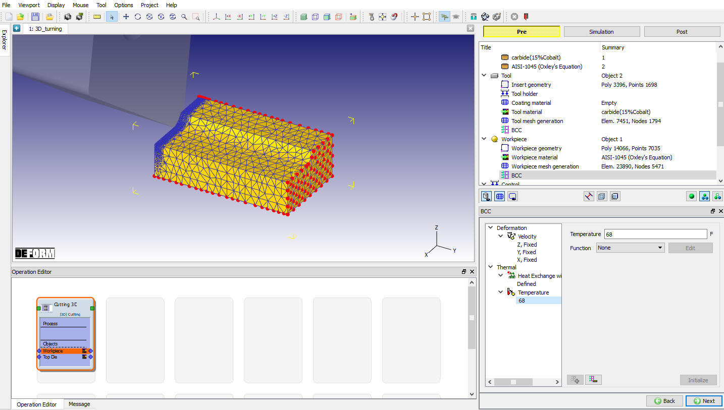
Assigned Temperature Boundary Condition for workpiece
Tool Positioning
In the ‘Controls’ menu, click on ![]() , Check the position of Insert. If Insert is not contact with workpiece using
, Check the position of Insert. If Insert is not contact with workpiece using ![]() method position the Insert and click
method position the Insert and click ![]() .
.
Tool wear setting
In this lab we are not calculating the tool wear so, uncheck the Define model to calculate tool wear check box (see Fig. 3DTL2.11.), Click ![]() to contact page.
to contact page.
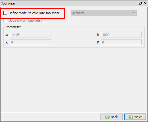
Tool wear setup window
Contact page
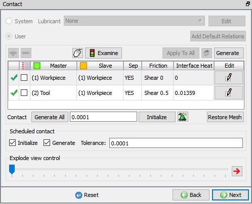
In Contact page, use default relations. Click on Tool - Workpiece relation ![]() button and define shear friction factor as 0.5 and the interface heat transfer coefficient as 0.01359 BTU/sec/in^2/F (as shown in Fig. 3DTL2.12.), click on
button and define shear friction factor as 0.5 and the interface heat transfer coefficient as 0.01359 BTU/sec/in^2/F (as shown in Fig. 3DTL2.12.), click on ![]() to generate contact. Click
to generate contact. Click ![]() to Step Control page.
to Step Control page.
Contact page
Step Control page
Check the ‘Simulation Controls’ and set the length of cut as ‘0.3 in’ (Full length of cut) and leave the rest as default values and proceed to generate the Database.
Generate Database
In Generate DB page, click on the ![]() button to generate the database. Observe the message in Message tab informing database generation status.
button to generate the database. Observe the message in Message tab informing database generation status.
Running simulation
Once the database has been generated switch to the Simulation mode by clicking on ![]() button above the operation tree. Click on the
button above the operation tree. Click on the ![]() action label to open the Run Options dialog as shown in Fig. 3DTL2.13. Use the default ContinueRun option to select “Continue from the last step ” (from step -1) option and then select the Simulation mode as Interactive radio button. Click on
action label to open the Run Options dialog as shown in Fig. 3DTL2.13. Use the default ContinueRun option to select “Continue from the last step ” (from step -1) option and then select the Simulation mode as Interactive radio button. Click on ![]() button to run the simulation.
button to run the simulation.
To define MPI settings, click on ![]() button, Run Options window will expand and displays options to define MPI settings for simulation (max number of processors that can be defined depend on your 3D MPI license).
button, Run Options window will expand and displays options to define MPI settings for simulation (max number of processors that can be defined depend on your 3D MPI license).
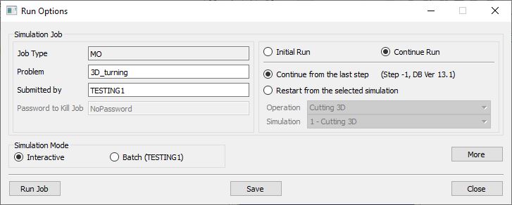
Run Simulation Window
Monitor the progress of the simulation by looking at the Simulation Message and Simulation Log tab, making sure that the ![]() option is checked. User can view the cutting process as the simulation proceeds to the specified cutting length from Simulation graphics.
option is checked. User can view the cutting process as the simulation proceeds to the specified cutting length from Simulation graphics.
Post Processing
When the simulation is completed, review the results by switching to Post mode using the ![]() button above the Simulation tool bar. Play through the steps of the simulation and look how the chip has been formed during cutting process.
button above the Simulation tool bar. Play through the steps of the simulation and look how the chip has been formed during cutting process.