DIEGEO
| (Object Data - 3D) |
|---|
| Last updated on : 09-08-2013 |
DIEGEO Object, Gtype, Npoints, Npoly
- Point(1), X(1), Y(1), Z(1)
-
: : :
Point(Npoints), X(Npoints), Y(Npoints), Z(Npoints)
- Poly(1), Point1(1), Point2(1), Point3(1), Point4(1)
-
: : : :
Poly(Npoly), Point1(Npoly), Point2(Npoly), Point3(Npoly), Point4(Npoly)
| OPERAND | DESCRIPTION | DEFAULT |
|---|---|---|
| Object | Object number | None |
| Gtype | Geometry type = 1 Polygon description = 2 Point description = 3 Cross section(2D XYR format) | None |
| Npoints | Number of points used in the geometry | None |
| Npoly | Number of elements describing the geometry | None |
| Point(i) | Point number of ith data point | None |
| X(i) | X coordinate of ith data point | None |
| Y(i) | Y coordinate of ith data point | None |
| Z(i) | Z coordinate of ith data point | None |
| Poly(i) | Connectivity of ith polygon | None |
| Point1(i) | 1st point of ith polygon | None |
| Point2(i) | 2nd point of ith polygon | None |
| Point3(i) | 3rd point of ith polygon | None |
| Point4(i) | 4th point of ith polygon | None |
DEFINITION
DIEGEO specifies the boundary geometry of an object.
REMARKS
DIEGEO boundary geometry may be used to specify a geometric profile of a rigid object or to define the object geometry for automatic mesh generation. DIEGEO information is described by a list of points and the connectivity of those points by three or four node polygons. Polygon description is selected by specifying a Gtype of 1. The order in which the polygon’s points are defined are displayed in the following figures. 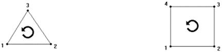 DIEGEO Surface Geometry Npoints is the number of points in the list which are used in the objects definition. This is followed by a list of 1 to Npoints of X, Y, and Z coordinates for each point. Npoly is the number of polygons which make up the object’s geometry. Following the listing of points is a listing of all polygons defining the object’s surface. For three node polygons, the Point4(i) will be a repeat of Point1(i). The profile geometry must be continuous, but does not need to represent a closed boundary. For each polygon in the geometry, the data should be ordered counterclockwise. Applicable object types: Rigid, Elastic, Plastic, Elastoplastic, Porous
DIEGEO (Rotational Surface Geometry) | Last updated on : 09-08-2013
—|—
DIEGEO Object, Gtype, Npoints
- Point(1), X(1), Y(1), Z(1)
-
: : :
Point(Npoints), X(Npoints), Y(Npoints), Z(Npoints)
| OPERAND | DESCRIPTION | DEFAULT |
|---|---|---|
| Object | Object number | None |
| Gtype | Geometry type = 1 Polygon description = 2 Point description = 3 Cross section(2D XYR format) | None |
| Npoints | Number of points used in the geometry | None |
| Point(i) | Point number of ith data point | None |
| X(i) | X coordinate of ith data point | None |
| Y(i) | Y coordinate of ith data point | None |
| Z(i) | Z coordinate of ith data point | None |
DEFINITION
DIEGEO specifies the boundary geometry of an object rotated about CNTRAX.
REMARKS
DIEGEO boundary geometry may be used to specify a geometric profile of a rigid object. DIEGEO information is described by a list of points. For Gtype equal to 2, a point description is selected. By defining a CNTRAX which lies in the same plane as the list of Point(i), the object’s geometry is defined by rotating the cross section around CNTRAX. Npoints is the number of points in the list which are used in the objects definition. This is followed by a list of 1 to Npoints of X, Y, and Z coordinates for each point. The profile geometry must be continuous, but does not need to represent a closed curve. If the geometry is a closed curve, the data should be ordered counterclockwise. If the geometry is not a closed curve, the geometry should be ordered counterclockwise such that the rigid object interior lies to the left of the profile geometry as would be the case if the entire closed shape had been drawn. Lines of symmetry should lie on either the global X or Y axis. Applicable object types: Rigid, Elastic, Elastoplastic, Porous
DIEGEO (Rotational Surface Geometry) | Last updated on : 09-08-2013
—|—
DIEGEO Object, Gtype, Npoints, Npoints1
Point(1), X(1), Y(1), Z(1)
Point(2), X(2), Y(2), Z(2)
- Point(3), X(3), Y(3), R(3)
-
: : :
Point(Npoints), X(Npoints), Y(Npoints), R(Npoints)
Point(Npoints+1), X(Npoints+1), Y(Npoints+1), R(Npoints+1)
Point(Npoints+2), X(Npoints+2), Y(Npoints+2), R(Npoints+2)
| OPERAND | DESCRIPTION | DEFAULT |
|---|---|---|
| Object | Object number | None |
| Gtype | Geometry type = 1 Polygon description = 2 Point description = 3 Cross section (2D XYR format) | None |
| Npoints | Number of points used in the geometry | None |
| Npoints1 | Number of rotational center and axis | 2 |
| Point(1) | Rotational center | None |
| Point(2) | Rotational axis | None |
| Point(i) | Point number of ith data point | None |
| X(i) | X coordinate of ith data point | None |
| Y(i) | Y coordinate of ith data point | None |
| R(i) | Radius of ith data point | None |
DEFINITION
DIEGEO specifies the boundary geometry of an object in 2D XYR format.
REMARKS
DIEGEO boundary geometry may be used to specify a cross section of a object. DIEGEO information is described by a list of points. Npoints is the number of points in the list which are used in the objects definition plus 2. Npoints1 is one rotational center and one rotaional axis, it equals 2. For Gtype equal to 3, 1st line is rotational center(X,Y,Z). For Gtype equal to 3, 2nd line is rotational axis(X,Y,Z). From 3rd line, followed by a list of 1 to Npoints-2 of X, Y, and R coordinates for each point. EXAMPLE DIEGEO 1 3 9 2 1 1.0000000E-01 2.0000000E-01 3.0000000E-01 2 4.0000000E-01 5.0000000E-01 6.0000000E-01 3 2.2000000E+00 3.4628230E+00 0.0000000E+00 4 3.0000000E-01 3.4628230E+00 0.0000000E+00 5 3.6704000E-01 2.8956030E+00 0.0000000E+00 6 4.2897730E-01 2.3715000E+00 7.4999300E-01 7 9.4322000E-01 2.2528330E+00 0.0000000E+00 8 2.2000000E+00 1.9628230E+00 0.0000000E+00 9 2.2000000E+00 3.4628230E+00 0.0000000E+00 Applicable object types: Rigid, Elastic, Plastic, Elastoplastic, Porous