3D Hot Forming Lab
In this lab we will setup Tee forging operation in Forming Express operation.
Operation 1 : Upsetting Operation
Operation 2 : Finish Forge operation
: Upsetting operation
Creating a New Problem
On a Windows machine , go to the ![]() button select DEFORM-v1x.xxx (.xxx indicates version number E.g. v14.0.2) and select DEFORM GUI Main vxx.xx from the menu. The DEFORM GUI Main window will appear, as shown in Fig. 3DHFL1.1.
button select DEFORM-v1x.xxx (.xxx indicates version number E.g. v14.0.2) and select DEFORM GUI Main vxx.xx from the menu. The DEFORM GUI Main window will appear, as shown in Fig. 3DHFL1.1.
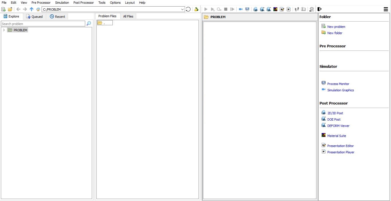
DEFORM GUI Main window
Create a new problem either by selecting File ![]() New Problem or by clicking the New Problem
New Problem or by clicking the New Problem ![]() icon. The Problem Setup window will appear as shown in Fig. 3DHFL1.2. Select “Integrated Manufacturing Process “ radio button and unit system as “English “ radio button in unit field. Define Problem Name as “ Tee “ and make sure the “Show option dialog” check box is turned on (if we do not turn on the “Show option dialog ” check box, then we will not get the New Project dialog in MO UI). Then click on
icon. The Problem Setup window will appear as shown in Fig. 3DHFL1.2. Select “Integrated Manufacturing Process “ radio button and unit system as “English “ radio button in unit field. Define Problem Name as “ Tee “ and make sure the “Show option dialog” check box is turned on (if we do not turn on the “Show option dialog ” check box, then we will not get the New Project dialog in MO UI). Then click on ![]() button to open a new Problem using the Deform Integrated Manufacturing Process.
button to open a new Problem using the Deform Integrated Manufacturing Process.
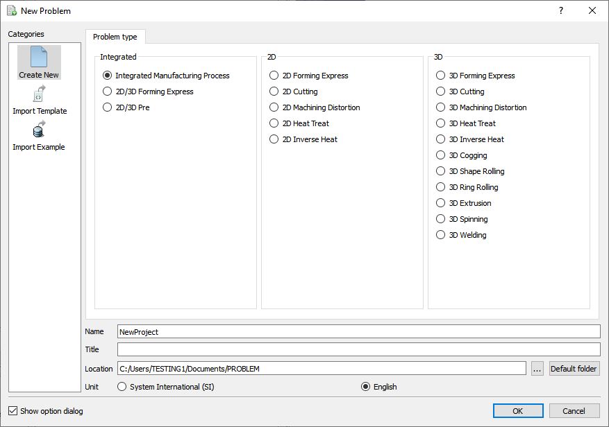
Problem type selection window
Integrated Manufacturing Process will open (see Fig. 3DHFL1.3.), at this point user will be prompted to specify a project name (system will create a separate folder with this project name) and title for this session. In this session we will use “**Tee** “ as the project name. Click on ![]() to continue to open the operation.
to continue to open the operation.
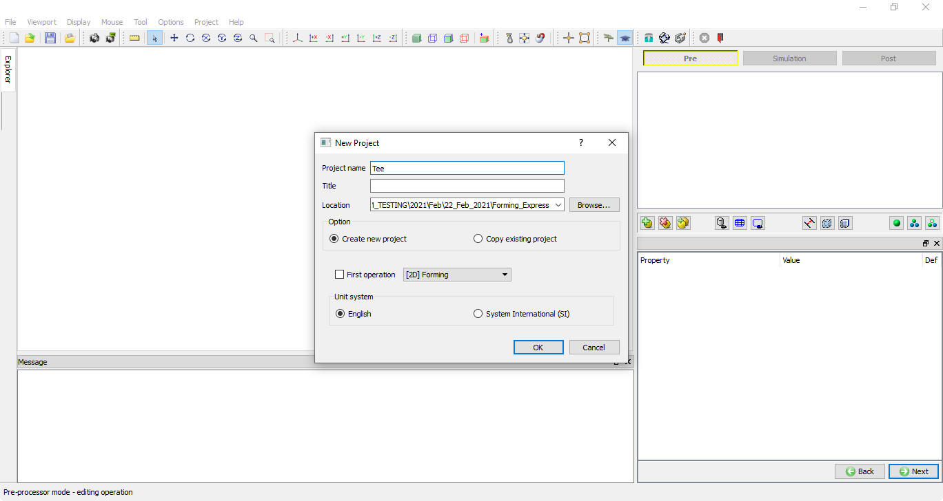
Problem location selection window
Adding 3D Forming Express operation - Bush
Once you click on Finish button, a Multiple Operation wizard will open to setup the problem. Add3D Forming Express operation from Operations list in Explorer. Operation can be add by clicking on ![]() button next to 3D Forming express operation (see Fig. 3DHFL1.4.) or user can also add by drag and drop into the Operation Editor.
button next to 3D Forming express operation (see Fig. 3DHFL1.4.) or user can also add by drag and drop into the Operation Editor.
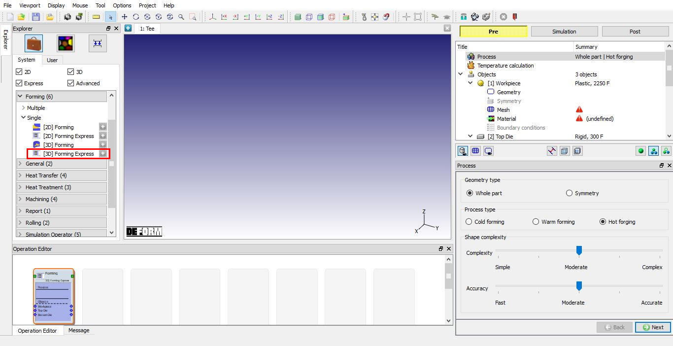
Added 3D Forming Express operation into Operation editor
Change Operation Name
Change the Operation name to “Bush “ by double click on Forming field in Operation editor as shown in Fig. 3DHFL1.5.
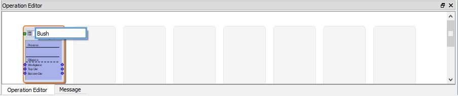
Changing Operation name from Operation Editor
Define Process settings
In Process page , select Process type as Hot Forging by selecting Hot Forging radio button. For this lab, we will simulate the whole part, by default Whole part will be selected if not select Geometry type as Whole part. The shape complexity and simulation accuracy slider bars influence the mesh settings and number of time steps used in the simulation. This in turn, influences the run time and level of details available in the simulation. For this simulation, we will use a “Simple ” geometry and “Fast ” calculations, so drag both slider bars all the way to the left as shown in Fig. 3DHFL1.6. then click ![]() .
.

Process page
Select Thermal Calculation
For this simulation, we will run with constant temperature (isothermal). This means that an initial workpiece temperature will be assigned, but DEFORM will neglect any changes in temperature during the calculations. Select Constant temperature (Isothermal) radio button as shown in Fig. 3DHFL1.7. Click on ![]() .
.
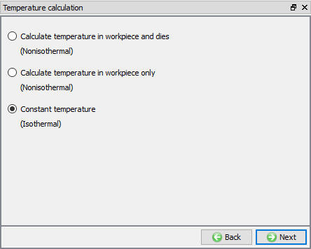
Thermal calculation mode selection page
Select Number of Objects
This simulation will have 1 workpiece and 2 dies, use default selection as shown in Fig L1.8 then click .
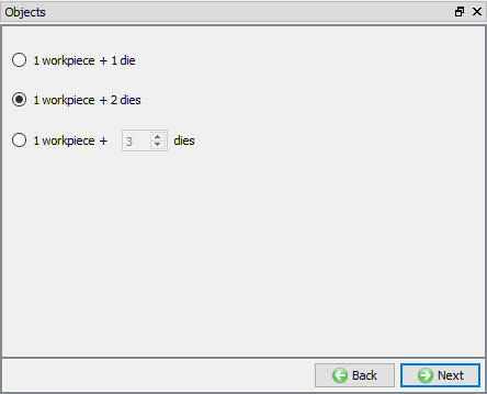
Number of Objects window
Workpiece General Definition
The workpiece will have an initial temperature of 2250°F, Change the WorkpieceTemperature to 2150°F as shown in Fig. 3DHFL1.9. Click on ![]() .
.
Note: There is an “import object” button on the “object” page. This is for importing complete object data from another object data file.

Workpiece Object page
Import Workpiece Geometry
In Geometry page, click on Load Geometry from Library ![]() button, Import TeeBillet.stl file as shown in Fig. 3DHFL1.10.
button, Import TeeBillet.stl file as shown in Fig. 3DHFL1.10.

Import Geometry page
Check the Geometry by clicking on ![]() action label. The “Geometry Checking Result” window contains a description of what constitutes a legal geometry as shown in Fig. 3DHFL1.11. Click on
action label. The “Geometry Checking Result” window contains a description of what constitutes a legal geometry as shown in Fig. 3DHFL1.11. Click on ![]() .
.
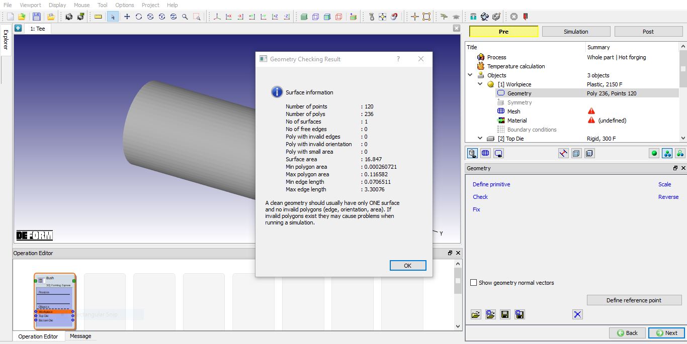
Check geometry window
Workpiece mesh Generation
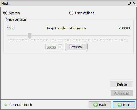
Generate mesh for the system type mesh settings value by click on![]() option as shown in Fig. 3DHFL1.12. Click on
option as shown in Fig. 3DHFL1.12. Click on ![]() to Material page.
to Material page.
Workpiece Mesh page
Assign Material for Workpiece
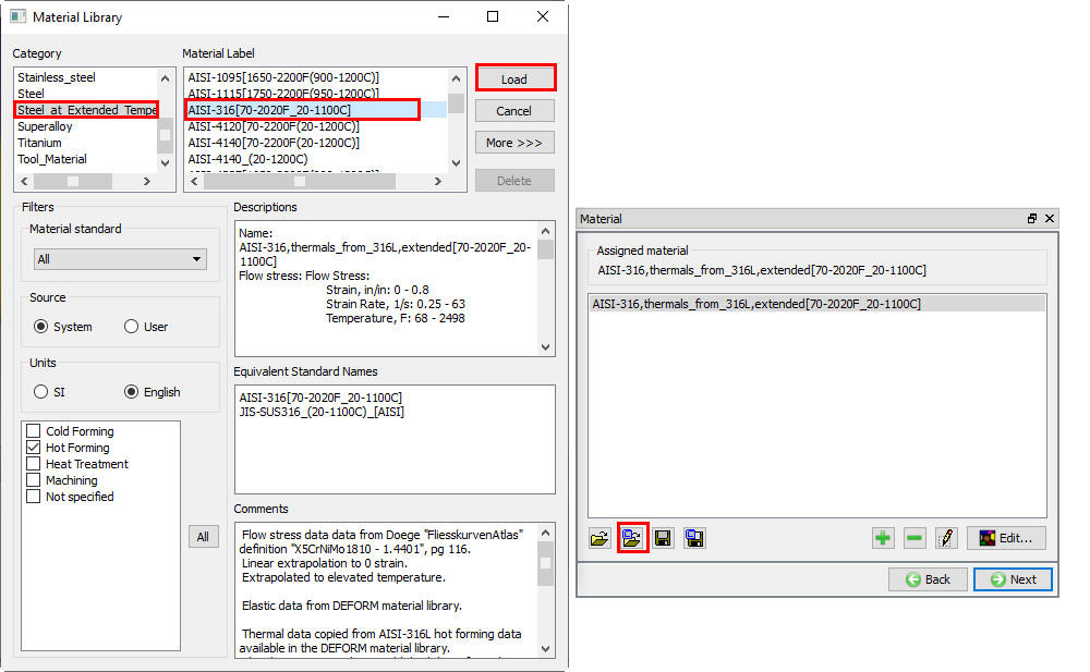
In Material window, load the material AISI-316[70-2020F(20-1100C)] from DEFORM Material library, from Steel_at_Extended_Temperature category using ![]() (Load material data from library) option. This can be done as shown in below Fig. 3DHFL1.13. by clicking
(Load material data from library) option. This can be done as shown in below Fig. 3DHFL1.13. by clicking ![]() button. Material can also be loaded from Materials list in Explorer. Then click on
button. Material can also be loaded from Materials list in Explorer. Then click on ![]() until Top Die page.
until Top Die page.
Material window
Top Die Definition
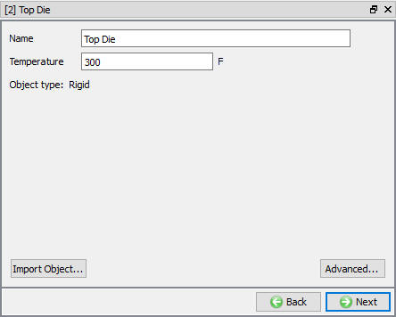
In Top Die page, use the default Object Temperature (300 °F) as shown in Fig. 3DHFL1.14., Click on ![]() .
.
Top Die page
Import Top Die geometry
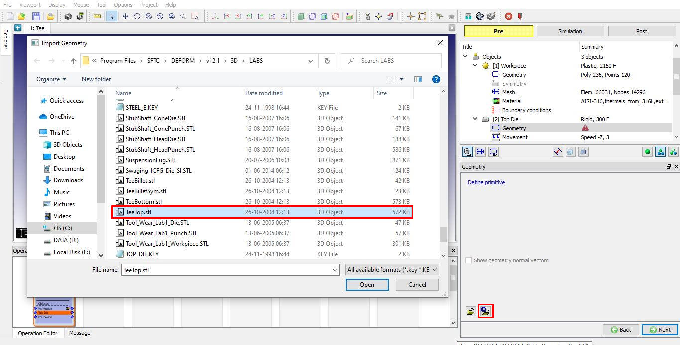
Click on Load Geometry from Library ![]() button, Import TeeTop.stl file as shown in Fig. 3DHFL1.15. Then check the geometry using
button, Import TeeTop.stl file as shown in Fig. 3DHFL1.15. Then check the geometry using ![]() option. Click
option. Click ![]() .
.
Import Geometry option
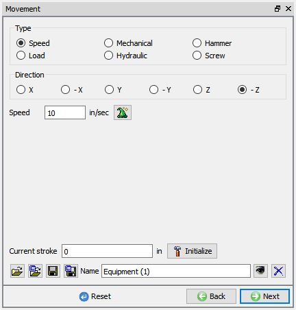
Assign Top Die movement
Under the movement options, select speed option. Be sure movement is in the –Z direction and enter a speed of 10 in/sec as shown in Fig. 3DHFL1.16. Click ![]() .
.
Top Die Movement page
Bottom Die Definition
In Bottom Die page, use the default Object Temperature(300 °F), Click on ![]() .
.
Import Bottom Die Geometry
Click on Load Geometry from Library ![]() button, Import TeeBottom.stl file. Then check the geometry using
button, Import TeeBottom.stl file. Then check the geometry using ![]() option. Click on
option. Click on ![]() .
.
Object Positioning
We will perform this operation with the workpiece in vertical direction. We will first position the workpiece on the bottom die. To make it easier to see, change to “User Defined Object Display ” mode in the control bar at the bottom of the object tree. Select Top Die in Object mode window and uncheck the check box in Visible column as shown in Fig. 3DHFL1.17., then click ![]() .
.
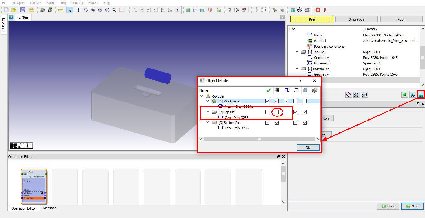
Object mode window to Turn of Top die in Display window
Click on ![]() option object positioning will open, select
option object positioning will open, select ![]() positioning. Select the workpiece. Use the mouse to pick a point around the center of the workpiece, and then select the “X ” axis as the axis of rotation. Enter an angle of 90 degrees, and
positioning. Select the workpiece. Use the mouse to pick a point around the center of the workpiece, and then select the “X ” axis as the axis of rotation. Enter an angle of 90 degrees, and ![]() . The workpiece should now be positioned vertical. (See Fig. 3DHFL1.18.)
. The workpiece should now be positioned vertical. (See Fig. 3DHFL1.18.)
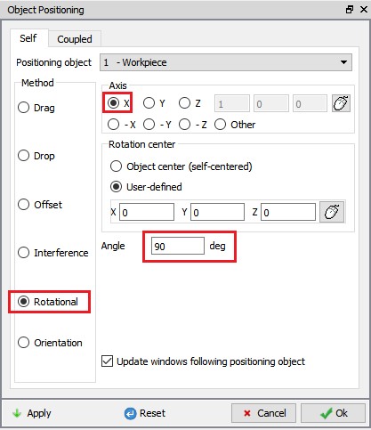
Object positioning window
Switch to ![]() positioning. Click on the “X ” or “Y ” axis and use the mouse to drag the billet to a flat spot on the die, not too close to either the forming cavity or the edge of the die. Use
positioning. Click on the “X ” or “Y ” axis and use the mouse to drag the billet to a flat spot on the die, not too close to either the forming cavity or the edge of the die. Use ![]() positioning to place the billet on the bottom die. (See Fig. 3DHFL1.19.)
positioning to place the billet on the bottom die. (See Fig. 3DHFL1.19.)
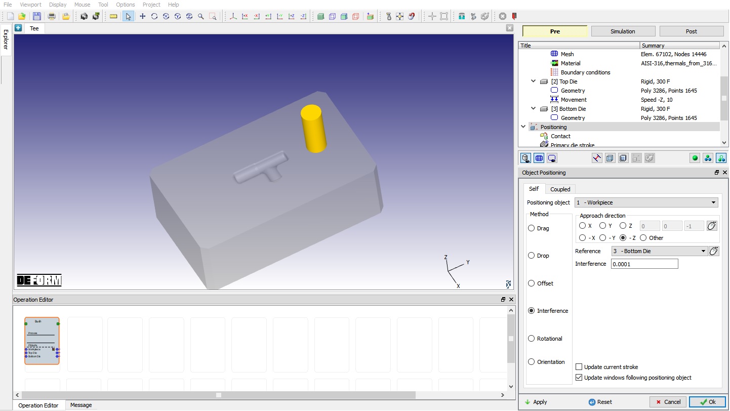
Positioning the billet on the bottom die
Now click on User defined mode ![]() and check the Top Die visible check box, then position Top die using Interference Positioning on Billet so that it is in contact with the billet. Click on
and check the Top Die visible check box, then position Top die using Interference Positioning on Billet so that it is in contact with the billet. Click on ![]() and
and ![]() .
.
Contact (Inter object Relation) Definition
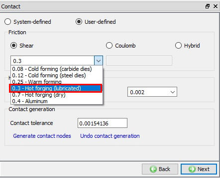
Select Userdefined - “Hot forging (lubricated) ” for friction condition as shown in Fig. 3DHFL1.20. and click on ![]() . DEFORM will automatically mark the nodes that are initially in contact with the die. Click
. DEFORM will automatically mark the nodes that are initially in contact with the die. Click ![]() .
.
Contact generation page
Primary Die stroke definition
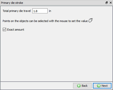
The primary die stroke is an estimate of the distance the die will travel during forming. This value does not have to be exact (exact stopping criteria will be specified at the next screen).
For this problem, we will upset a 3.300” billet to 1.500”. The primary die stroke is about 1.800”, so define Total Primary die travel as 1.8 inches as shown in Fig. 3DHFL1.21. Click ![]() .
.
Primary Die stroke page
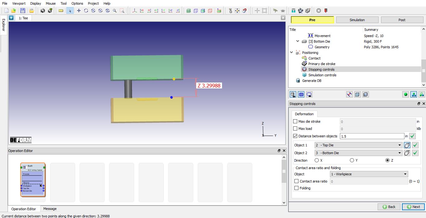
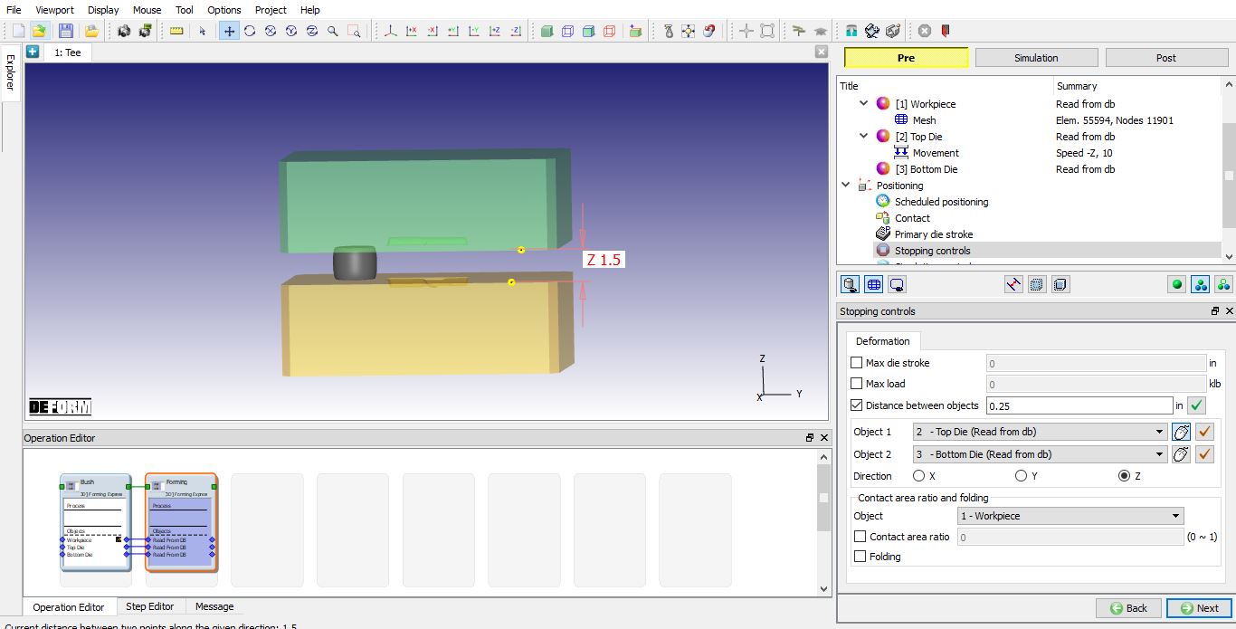
Stopping Controls Definition
We want to stop when the dies are 1.500” apart. So set “Stop Controls” to “Distance between objects”. Enter a value of 1.5 ” as shown in Fig. 3DHFL1.22. Turn on shaded mesh, and select a point on the bottom surface of the top die, and a second point on the top surface of the bottom die. Click ![]() .
.
Stopping controls page
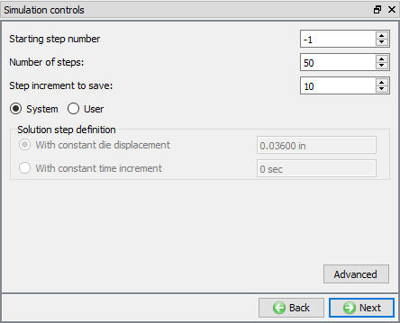
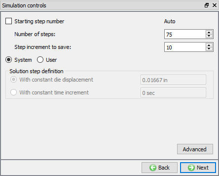
Simulation Controls Definition
The number of simulation steps and step increment are established by the object shape complexity slider bar settings. If you want to change the default values, you can do it at this window. We will accept default values for this lab as shown in Fig. 3DHFL1.23., then click on ![]() .
.
Simulation controls
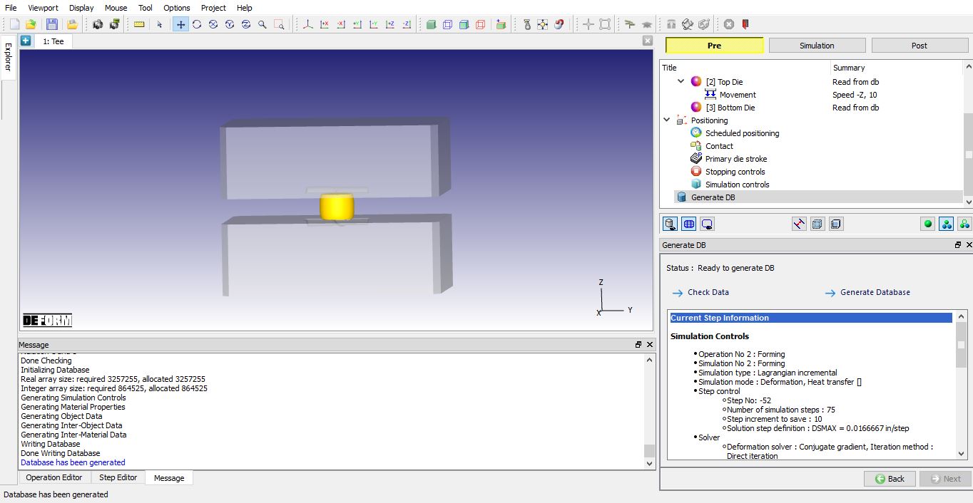
Generate Database
In Generate DB page. Click the ![]() button to have the program check to see if anything was missed in the problem setup. During the checking process:
button to have the program check to see if anything was missed in the problem setup. During the checking process:
Messages in the red color signify data that needs to be fixed before a simulation can be run (such as when you forget to define any material data).
Click on ![]() button to generate the database. When the program is done writing the database, click on
button to generate the database. When the program is done writing the database, click on ![]() tab to run simulation.
tab to run simulation.
Running simulation
Click on the ![]() action label to open the Run Options dialog as shown in Fig. 3DHFL1.24. Use the default Continue Run option to select “Continue from the last step ” (from step -1) option and then select the Simulation mode as Interactive and click on
action label to open the Run Options dialog as shown in Fig. 3DHFL1.24. Use the default Continue Run option to select “Continue from the last step ” (from step -1) option and then select the Simulation mode as Interactive and click on ![]() button to run the simulation.
button to run the simulation.
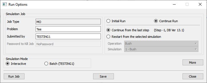
Run Simulation window
The progress of the simulation can be monitored as it is running by looking at the Simulation Message tab and Simulation Graphics from the Graphics display region in Simulation mode. As long as the ![]() option is checked in Simulation Message tab, which is the default setting, the Message file will refresh automatically.
option is checked in Simulation Message tab, which is the default setting, the Message file will refresh automatically.
The Message file provides information about which simulation step the simulation is currently on and also gives information dealing with how well the simulation is running.
When the simulation is finished without any issues, check the messages in Message file, when operation completes we will see messages as .”THE DISTANCE BETWEEN TWO OBJECTS ( 2 3): 1.5000000 HAS REACHED THE SPECIFIED LIMIT 1.5000000 “.
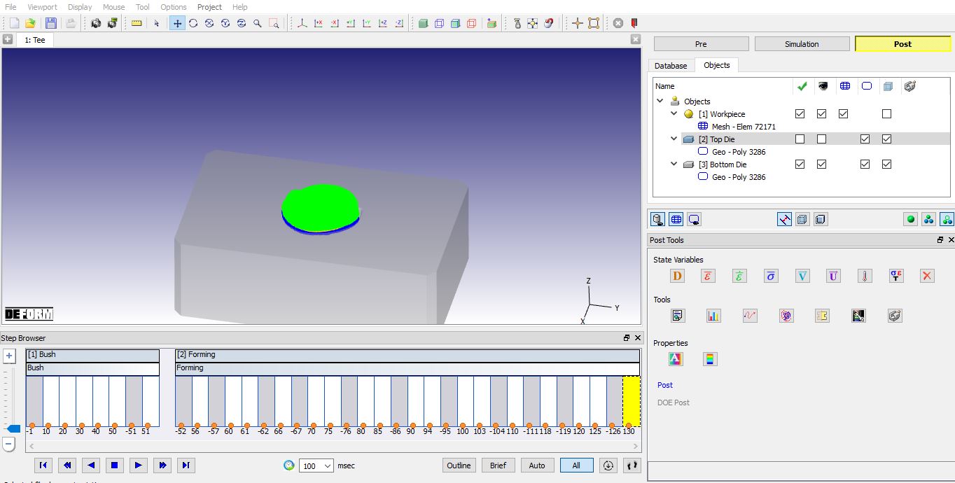
Post process the upsetting operation
After completion of Simulation, switch to ![]() mode for post processing. Click on
mode for post processing. Click on ![]() button in Step Browser to see all saved steps as shown in Fig. 3DHFL1.25.
button in Step Browser to see all saved steps as shown in Fig. 3DHFL1.25.
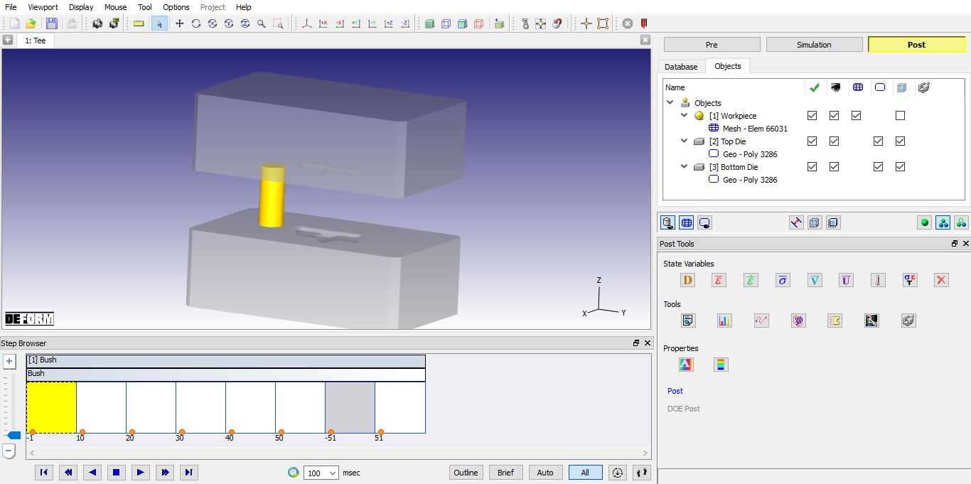
MO Post mode
State Variable:
From the state variable menu, click on ![]() button, select strain effective variable, Display type as Solid and click on
button, select strain effective variable, Display type as Solid and click on ![]() as shown in Fig. 3DHFL1.26, you can display line or shaded contours. It is also possible to select solid shading, or element shading. Experiment with each of these settings.
as shown in Fig. 3DHFL1.26, you can display line or shaded contours. It is also possible to select solid shading, or element shading. Experiment with each of these settings.
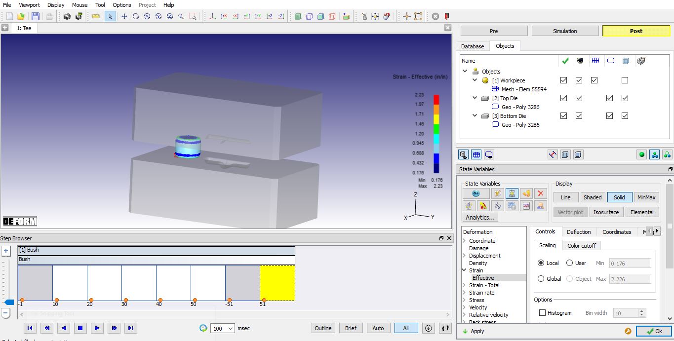
Strain - Effective State variable plot
Point Tracking:
Select ![]() point tracking. Select few points on the object, and track the points using
point tracking. Select few points on the object, and track the points using ![]() option (see Fig. 3DHFL1.27.). If a state variable is displayed, the values of the variables will be graphed at these points.
option (see Fig. 3DHFL1.27.). If a state variable is displayed, the values of the variables will be graphed at these points.
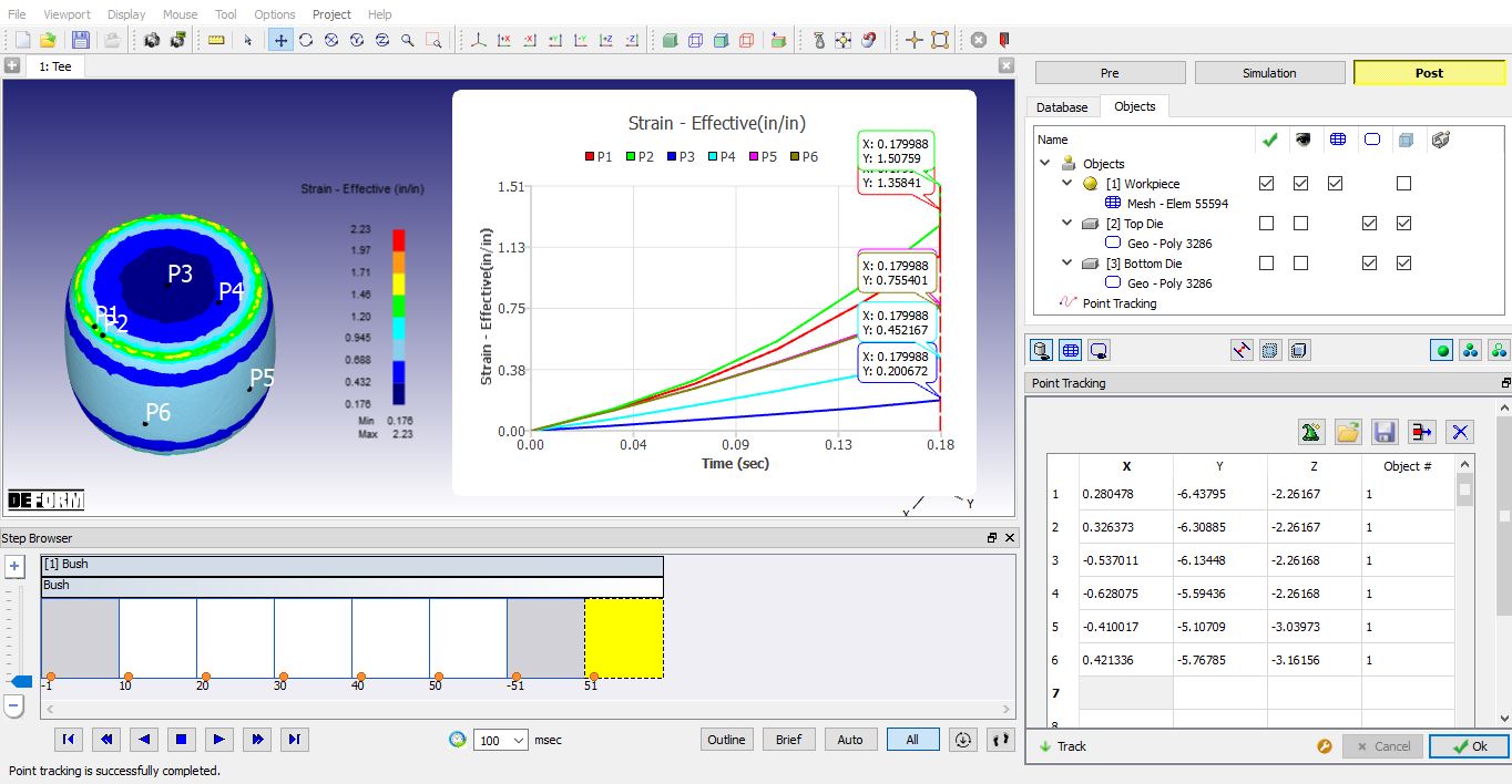
Point tracking
: Finish Forge operation
After completion of simulation switch to ![]() mode.
mode.
Add and Define 2nd operation
Add another Forming express operation to setup Finish forge operation. In this operation we are positioning the Workpiece over the cavity in Die and simulating the Finish forge operation.
Select batch mode:
Select 2nd operation from Operation editor, Setup type popup will appear and click on ![]() button (Since we are setting up second operation in Batch mode).
button (Since we are setting up second operation in Batch mode).
Change operation name:
Change operation name to “Finish Forge “ from Operation editor as shown in Fig. 3DHFL1.28.
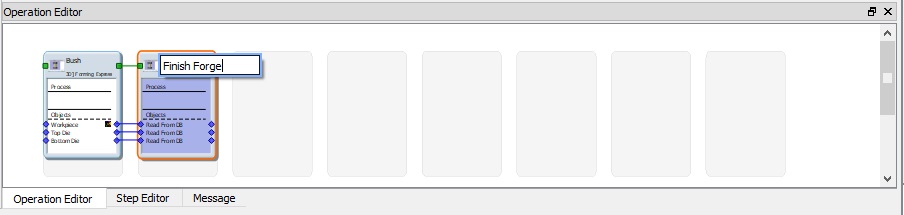
Changing operation name
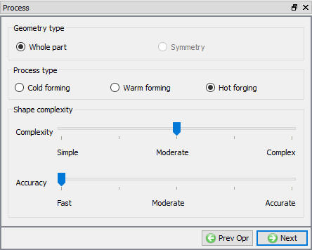
Define Process settings for finishing operation
Change the object shape complexity to “Moderate ”. Leave accuracy at “Fast “ as shown in Fig. 3DHFL1.29. and click on ![]() until Scheduled positioning page.
until Scheduled positioning page.
Process settings for finishing operation
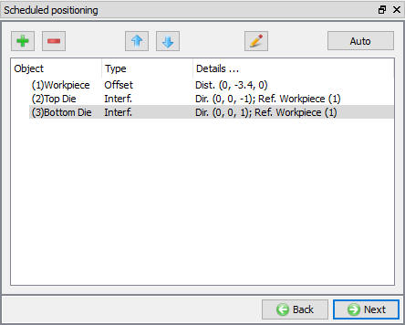
Scheduled positioning
Add relation by clicking on ![]() button, select positioning object as Workpiece and select Offset option, define the X and Y value to position the workpiece on Die cavity.
button, select positioning object as Workpiece and select Offset option, define the X and Y value to position the workpiece on Die cavity.
Similarly add relations to positionTop die on Workpiece in -Z direction and BottomDie below Workpiece in +Z Direction using Interference positioning options as shown in Fig. 3DHFL1.30. Click ![]() .
.
Scheduled positioning window
Contact (Inter object Relation) Definition
Select Userdefined - “Hot forging (lubricated) ” for friction condition as shown in Fig. 3DHFL1.20. Click on ![]() .
.
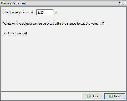
Defining Primary Die stroke
We will forge from an initial height of 1.500” to a flash height of 0.250”, for a total stroke of 1.250”. Enter 1.25 value as the primarydiestroke value as shown in Fig. 3DHFL1.31. Click on ![]() .
.
Primary Die stroke window
Stopping controls
We are forging to a flash thickness of 0.250”. So check the Distance between objects check box, Select points on the bottom of the top die, and the top of the bottom die. Enter a stopping distance of 0.250 and Select Z direction as shown in Fig. 3DHFL1.32. Click on ![]() .
.
Stopping controls window
Simulation controls
Use the Default System Step definition values as shown in Fig. 3DHFL1.33. and click ![]() .
.
Simulation controls window
Generating DB
When user visit DB generation page, you can see the objects are positioned with respect to Scheduled positioning data, check the position of Workpiece on Die cavity is ok, then check and Generate Database (see Fig. 3DHFL1.34.), after generating Database switch to ![]() mode to run the simulation.
mode to run the simulation.
Generate Database page
Running simulation
Click on the ![]() action label to open the Run Options dialog as shown in Fig. 3DHFL1.24. Use the default Continue Run option to select “Continue from the last step ” (from step -1) option and then select the Simulation mode as Interactive and click on
action label to open the Run Options dialog as shown in Fig. 3DHFL1.24. Use the default Continue Run option to select “Continue from the last step ” (from step -1) option and then select the Simulation mode as Interactive and click on ![]() button to run the simulation. As we click on
button to run the simulation. As we click on ![]() button simulation starts.
button simulation starts.
When the simulation is finished without any issues, check the messages in Message file, when operation completes we will see messages as,
“PROGRAM STOPPED!
THE DISTANCE BETWEEN TWO OBJECTS ( 2 3): 0.2500000 HAS REACHED THE SPECIFIED LIMIT 0.2500000 “.
After completion of simulation, switch to ![]() mode.
mode.
Post processing finishing operation
Play through the simulation. Did the part fill the die cavity? You may want to turn one or the other die off, or use transparency to better visualize the part.
Right click on the workpiece icon in the process tree and turn on display contact. Watch how the contact evolves as the part fills out die, see Fig. 3DHFL1.35.
Contact display to check the underfill
Plot theload-stroke curve as shown in Fig. 3DHFL1.36. Observe how the load increases as the part fills out the die and forms flash.
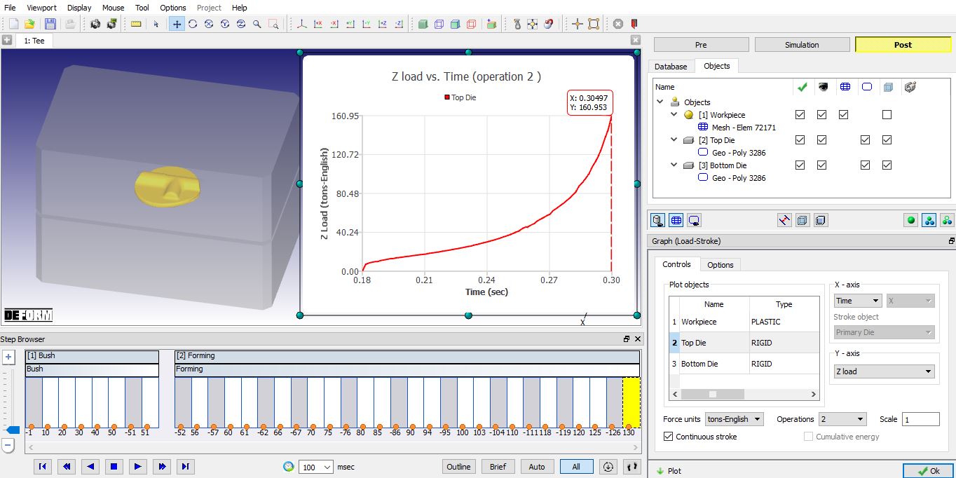
Load -Stroke Graph plot
Plot the strain rate during forming as shown in Fig. 3DHFL1.37. Observe what happens in the flash area.
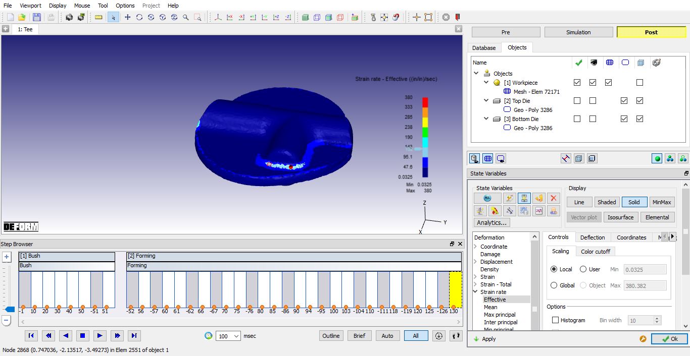
Strain Rate Effective state variable plot