3D Gear Mechanical Press Lab
In This we will setup simple Gear blank operation using Mechanical press movement in 3D Forming Express wizard.
Upset
Creating a New problem
On a Windows machine , go to the ![]() button select DEFORM-v1x.xxx (.xxx indicates version number E.g. v14.0.2) and select DEFORM GUI Main vxx.xx from the menu. The DEFORM GUI Main window will appear. Create a new problem either by selecting File
button select DEFORM-v1x.xxx (.xxx indicates version number E.g. v14.0.2) and select DEFORM GUI Main vxx.xx from the menu. The DEFORM GUI Main window will appear. Create a new problem either by selecting File ![]() New Problem or by clicking the New Problem
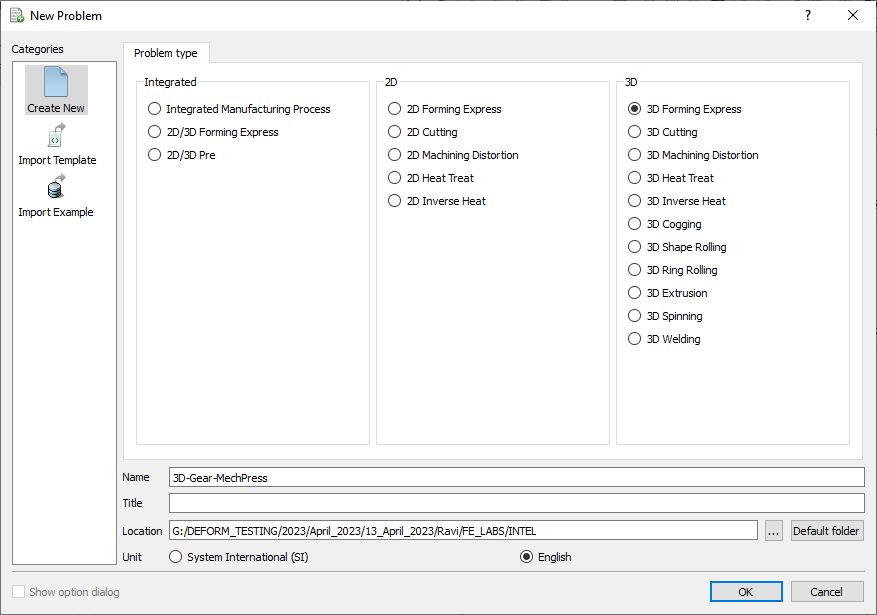
New Problem or by clicking the New Problem ![]() icon. The Problem Setup window will appear. Select “3D Forming Express “ radio button and unit system as “English “ radio button in unit field as shown in Fig. 3DGML1.1. Define Problem Name as “3D-Gear-MechPress “ and click on
icon. The Problem Setup window will appear. Select “3D Forming Express “ radio button and unit system as “English “ radio button in unit field as shown in Fig. 3DGML1.1. Define Problem Name as “3D-Gear-MechPress “ and click on ![]() button to open a new Problem using the Integrated Manufacturing Process.
button to open a new Problem using the Integrated Manufacturing Process.
Problem type selection window
Confirm that a 3D Forming Express operation tile is present in the operation editor. Rename the first operation to “Upset ” by double clicking on the operation tile in the operation editor (See Fig. 3DGML1.2.).
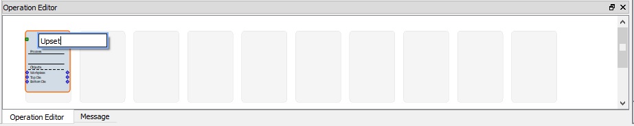
Renaming Operation name in Operation Editor
Process
In the Process page choose Symmetry , Hot forging and set both slider bars one notch below moderate to speed up the simulation time (see Fig. 3DGML1.3.). Click on ![]() to the temperature calculation page.
to the temperature calculation page.
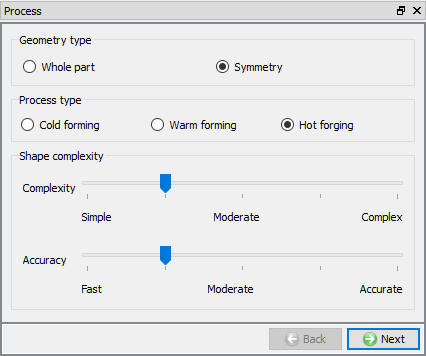
Process Page
Temperature Calculation
In the Temperature calculation page, select constant temperature (Isothermal). Selecting constant temperature means we are neglecting changes in workpiece temperature during forming. Click on ![]() to Objects.
to Objects.
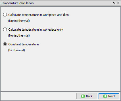
Temperature Calculation page
Object Page
In the objects page select 1 workpiece + 2 dies and click ![]() to the workpiece page.
to the workpiece page.
Workpiece
We will use an object temperature of 2200°F for our workpiece. Move to the geometry page for the workpiece.
Workpiece Geometry
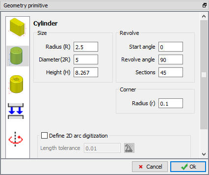
In the geometry page we will define primitive for our workpiece. Click on ![]() . Select Cylinder type and define the workpiece dimensions to 2.5 in Radius(R), 8.267 in Height(H), 0.1 in CornerRadius(r), with Revolveangle90 and Sections45(see Fig. 3DGML1.5.) Click
. Select Cylinder type and define the workpiece dimensions to 2.5 in Radius(R), 8.267 in Height(H), 0.1 in CornerRadius(r), with Revolveangle90 and Sections45(see Fig. 3DGML1.5.) Click ![]() to Close. Click
to Close. Click ![]() to proceed to the Symmetry page.
to proceed to the Symmetry page.
Defining the Workpiece Geometry
Workpiece Symmetry
Define Planar symmetry for workpiece on Symmetry surfaces. Select the surfaces as shown in Fig. 3DGML1.6. Click on ![]() to Generate Mesh.
to Generate Mesh.
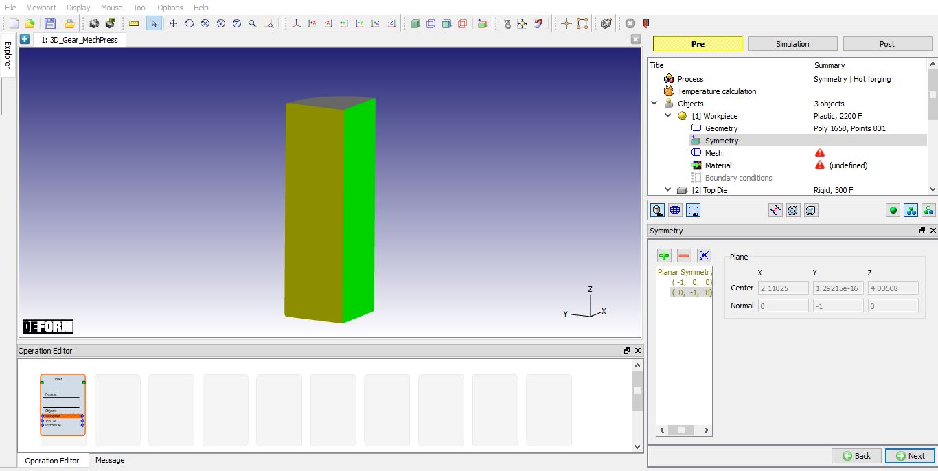
Workpiece Symmetry window
Workpiece Mesh
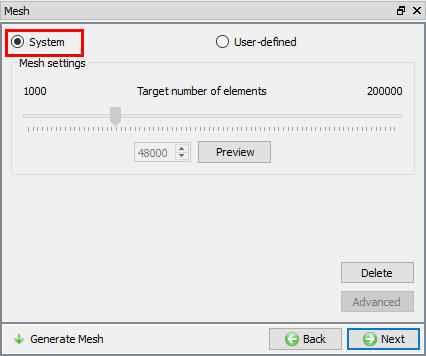
Generate mesh for the Systemtype mesh settings value by click on ![]() option as shown in Fig. 3DGML1.7. Click on
option as shown in Fig. 3DGML1.7. Click on ![]() to the material page for the workpiece.
to the material page for the workpiece.
Workpiece mesh generation
Workpiece Material
Click the ![]() (Load material from library) button as shown in Fig. 3DGML1.8. Select the Steel_at_Extended_Temperatures category, then AISI-8620[1550-2200F(850 -1200C)] and click the
(Load material from library) button as shown in Fig. 3DGML1.8. Select the Steel_at_Extended_Temperatures category, then AISI-8620[1550-2200F(850 -1200C)] and click the ![]() button. The material will be added to the material list and selected. Click
button. The material will be added to the material list and selected. Click ![]() until Top Die Geometry page.
until Top Die Geometry page.
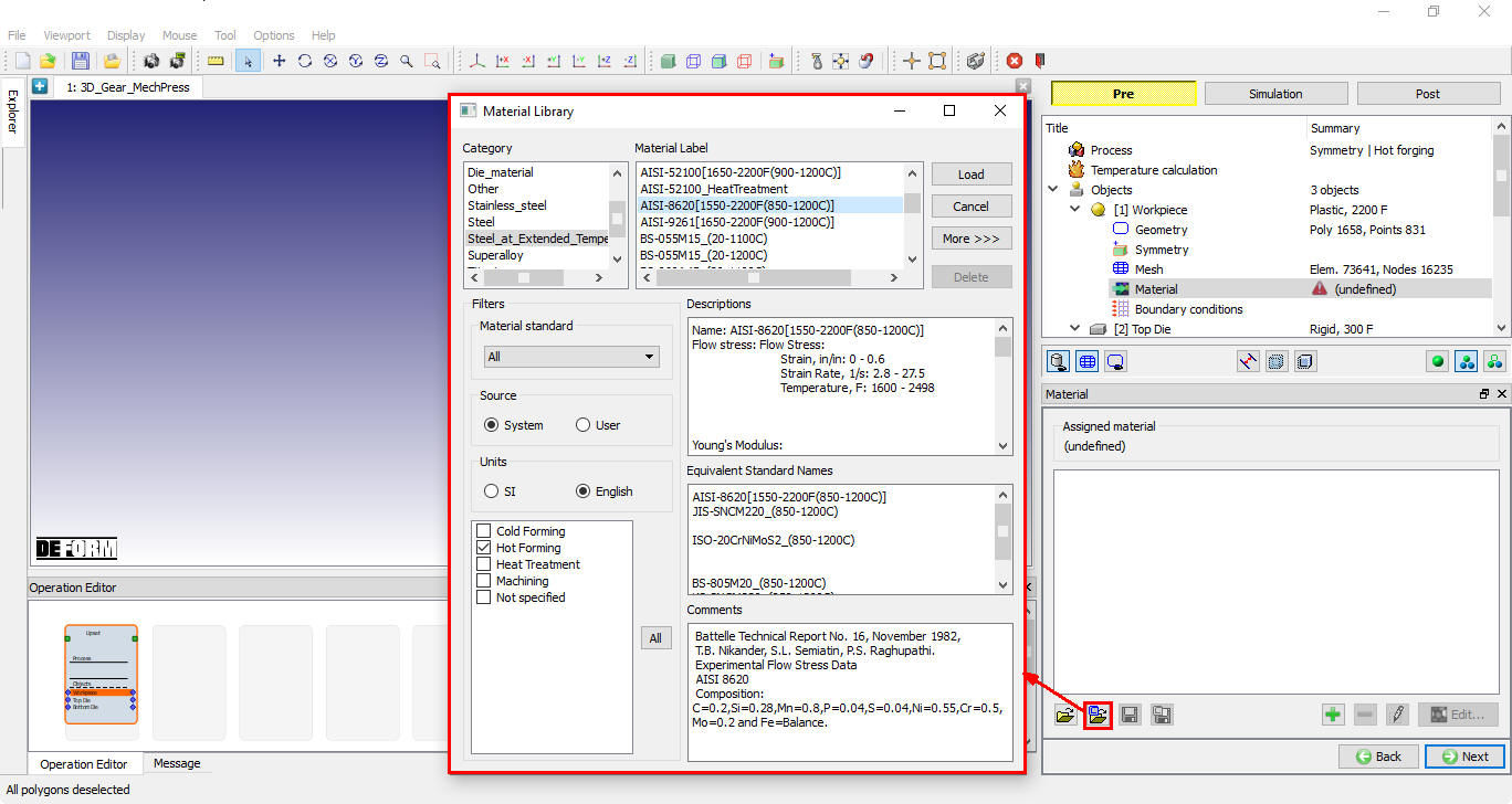
Workpiece material selection from Material Library
Top Die
Top Die Geometry
Click on ![]() button and import 3d_flat top die.stl from the 3D\ LABS folder located in the installation directory and Check the geometry. Mark symmetry surfaces using Mark surface as shown in Fig. 3DGML1.9. Click
button and import 3d_flat top die.stl from the 3D\ LABS folder located in the installation directory and Check the geometry. Mark symmetry surfaces using Mark surface as shown in Fig. 3DGML1.9. Click ![]() .
.
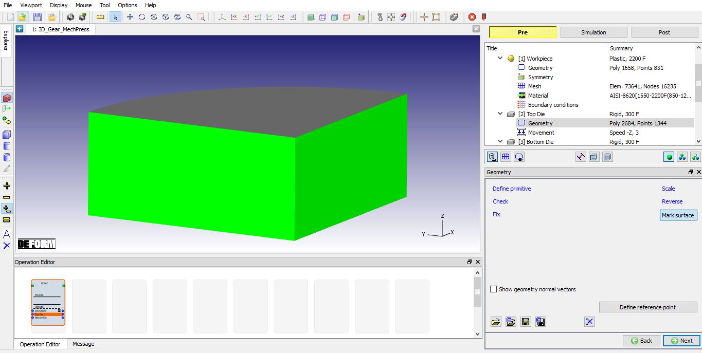
Assigning Symmetry plane for Top die using Mark Surface option
Top Die Movement page
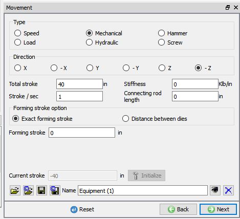
Here we will define our top die as a mechanical press. Select the mechanical press radio button and observe the options which that are available (see Fig. 3DGML1.10.).

Mechanical Press Movement page
Keep the default movement direction of –Z. Stiffness and connecting rod length are optional inputs for defining the mechanical press. For the first operation we will use a totalstroke of 40 inches and 1 stroke/sec. Select distance between dies and confirm the current stroke = -(total stroke). Click on until ![]() bottom die geometry page (see Fig. 3DGML1.11.).
bottom die geometry page (see Fig. 3DGML1.11.).
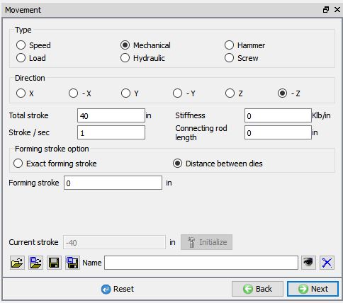
Top die movement data
Bottom Die
Bottom Die Geometry
In the bottom die geometry page Click on ![]() . Select Cylinder type and define the Bottom die dimensions to 8 inch Radius(R), 4 inch Height(H), with Revolveangle90 and Sections45 and click
. Select Cylinder type and define the Bottom die dimensions to 8 inch Radius(R), 4 inch Height(H), with Revolveangle90 and Sections45 and click ![]() to close (See Fig. 3DGML1.12.). Now click on Mark Surface and assign symmetry planes as we defined for Top die.
to close (See Fig. 3DGML1.12.). Now click on Mark Surface and assign symmetry planes as we defined for Top die.
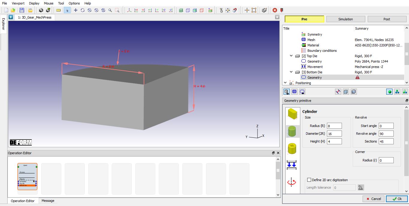
Bottom Die geometry
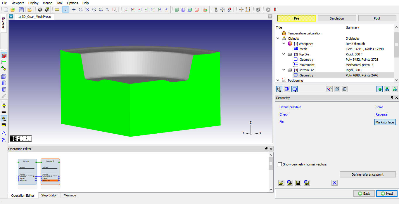
Observe the position of the three objects (see Fig. 3DGML1.13.). The top and bottom die are currently positioned inside of the workpiece which will result in excessive remeshing and unrealistic results. Click on ![]() until Positioning page.
until Positioning page.

Objects Position after creating
Positioning
In the positioning page, click the ![]() button. You should see the top and bottom die position above and below the workpiece. Automatic positioning performs two actions:
button. You should see the top and bottom die position above and below the workpiece. Automatic positioning performs two actions:
-
Interference position bottom die to workpiece while coupled with top die without updating stroke
-
Interference position top die to workpiece while updating stroke.
After the dies have been positioned, keep the default contact settings and skip to the stopping controls page.
Stopping Controls
For the distance between dies method we need to specify a distance between objects stopping criteria. Selected points similar to the ones displayed below.
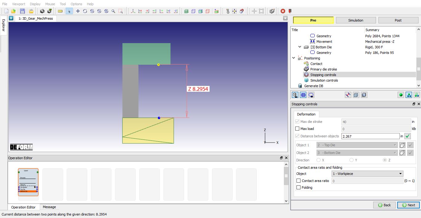
Distance between objects Stopping controls
For the first operation, we want the top die to travel 6 inches in order to create the correct shape. Input a die distance value of 2.267 inches for distance between objects (see Fig. 3DGML1.14.). Click on ![]() to primary die stroke page .
to primary die stroke page .
Primary Die Stroke
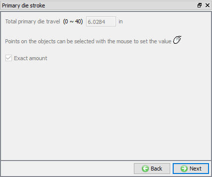
Notice the total primary die travel is set to roughly 6 inches. The distance between dies method automatically calculates total primary die travel for the user. When the exact amount checkbox is checked the value shown in the total primary die travel field is used as the forming stroke (see Fig. 3DGML1.15.). In operation 2 we will cover situations where exact amount is unchecked. Click ![]() until Simulation controls page.
until Simulation controls page.
Primary die stroke
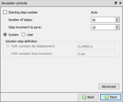
Simulation Controls
We will be using the default system options (see Fig. 3DGML1.16.) and proceed to the generate DB page.
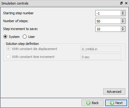
Simulation controls page
Generate DB
In Generate DB page. Click the ![]() button to have the program check to see if anything was missed in the problem setup. During the checking process:
button to have the program check to see if anything was missed in the problem setup. During the checking process:
Messages in the red color signify data that needs to be fixed before a simulation can be run (such as when you forget to define any material data).
Click on ![]() button to generate the database. When the program is done writing the database, Save the project and click on
button to generate the database. When the program is done writing the database, Save the project and click on ![]() mode to run the simulation.
mode to run the simulation.
Running Simulation - Operation 1
Click on the ![]() action label to open the Run Options dialog. Use the default Continue Run option to select “Continue from the last step ” option and then select the Simulation mode as Interactive and click on
action label to open the Run Options dialog. Use the default Continue Run option to select “Continue from the last step ” option and then select the Simulation mode as Interactive and click on ![]() button to run the simulation.
button to run the simulation.
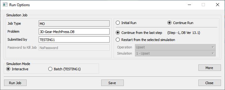
Run Simulation window
The progress of the simulation can be monitored as it is running by looking at the Simulation Message tab and Simulation Graphics from the Graphics display region in Simulation mode. As long as the ![]() option is checked in Simulation Message tab, which is the default setting, the Message file will refresh automatically.
option is checked in Simulation Message tab, which is the default setting, the Message file will refresh automatically.
Post process the results - Operation 1
After the simulation is completed, Switch to ![]() tab to view the result.
tab to view the result.
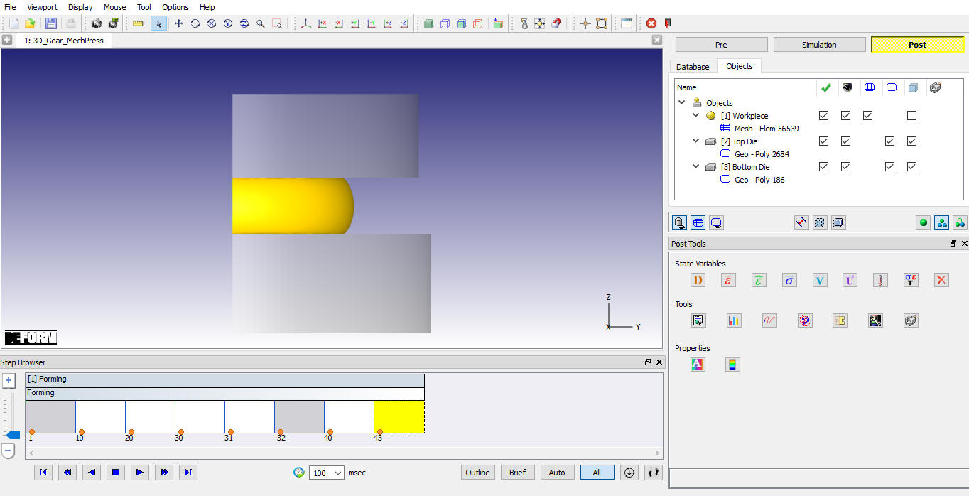
MO Post processor
Some important state variables can be selected directly from ‘Post Tools’ window and the rest can be accessed through State Variable dialog by clicking on ![]() icon.
icon.
Click on ![]() Graph (Load-Stroke) and plot Time (sec) vs Load (klb) and also plot Time (sec) Vs Speed (in/sec) for top die.
Graph (Load-Stroke) and plot Time (sec) vs Load (klb) and also plot Time (sec) Vs Speed (in/sec) for top die.
Strain Effective state variable plot for workpiece at 1st operation last step
Z -Load v/s Time Graph of Top die in 1st operation
Gear Finish
Problem Setup
Add a new 3D Forming Express operation and select ![]() as your method of defining the operation.
as your method of defining the operation.
Top Die
By default all objects will be passed to the second operation as read from DB objects. Skip to the top die page in the tree. All settings from the previous operation will be passed to operation 2 so there is no need to revisit the earlier pages. For the mechanical press it is best to never use a read from DB top die. Select Define as the object type to define new geometry for top die (see Fig. 3DGML1.21.).
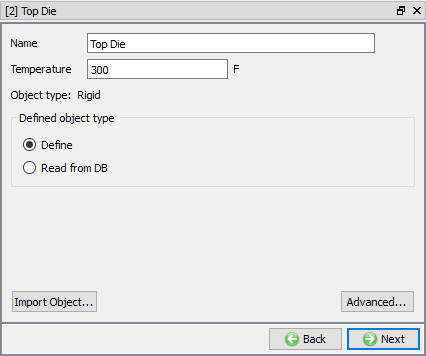
Top Die page
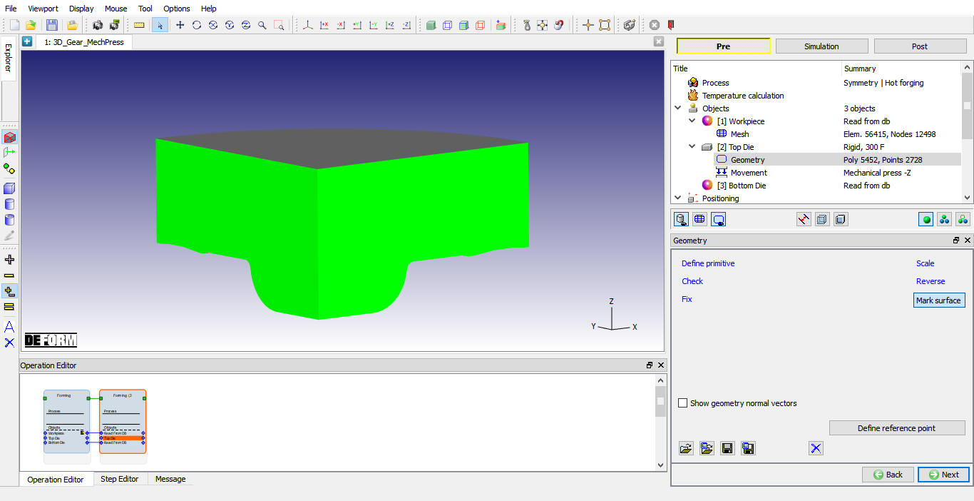
Top Die Geometry
Click ![]() to go to the geometry page for the top die. Import the geometry 3d_gear top die.stl from the 3D\ LABS folder located in the installation directory. Mark symmetry surfaces using Mark surfaces as shown in Fig. 3DGML1.22.
to go to the geometry page for the top die. Import the geometry 3d_gear top die.stl from the 3D\ LABS folder located in the installation directory. Mark symmetry surfaces using Mark surfaces as shown in Fig. 3DGML1.22.
Top die geometry import
Top Die Movement
Go to the top die movement page and select exact forming stroke. The previous press settings for total stroke and cycles per second are the same (see Fig. 3DGML1.23.). Click ![]() to Bottom Die object page.
to Bottom Die object page.
Top die movement data
Bottom Die
Select Define as the object type. Click on ![]() to the geometry page.
to the geometry page.
Bottom Die Geometry
Import 3d_**gear bottom die.stl** from the 3D\ LABS folder located in the installation directory. Mark Symmetry surfaces using Mark surface as shown in Fig. 3DGML1.24. Click on ![]() until the positioning page.
until the positioning page.
Bottom die geometry import
Positioning
For operation 2 we will use the bottom dead center position action check box to calculate our forming stroke. In order to use this action checkbox the top and bottom die must be positioned at bottom dead center.
Before positioning, take note of the forming stroke value in the top die movement page. In the positioning pageinterference position the top die down to the bottom die in the –Z direction.
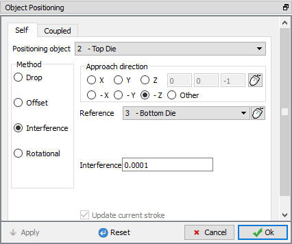
Interference positioning
Then offset position the top die by 0.2 inches in the Z direction. The dies are now at bottom dead center position. Switch to the top die movement page and notice the forming stroke and current stroke that are updated based on the positioning which was applied. For the mechanical press in Forming Express, forming stroke is always updated when the top die is positioned.
Primary Die Stroke
Click ![]() until the primary die stroke page. Take note that there is no positioning scheduled and the distance between objects stopping criteria is disabled in Stopping Controls page, because exact forming stroke was selected in the top die movement page.
until the primary die stroke page. Take note that there is no positioning scheduled and the distance between objects stopping criteria is disabled in Stopping Controls page, because exact forming stroke was selected in the top die movement page.
Primary Die stroke page
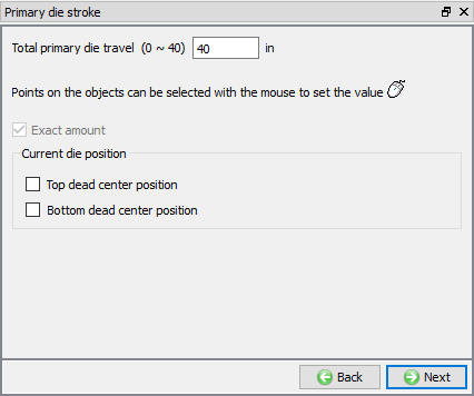
As mentioned previously, when exact amount is checked total primary die travel = forming stroke. The forming stroke was recently updated with positioning which explains the negative value seen for total primary die travel. Red text indicates that the value entered for total primary die stroke is outside of the legal range (See Fig. 3DGML1.26.).
It is up to the user to fix illegal total primary die travel value. Check the bottom dead center position check box and observe that the exact amount box is no longer checked as a result.
When exact amount is unchecked total primary die travel is not equal to forming stroke and is only used to calculate the step size for the simulation. The user is required to input an approximate value for how far the top die is expected to travel.
In this case the top die needs to travel approximately 2 inches to reach bottom dead center (see Fig. 3DGML1.27.).

Bottom dead center position checked in Primary die stroke page
The bottom dead center position check box will automatically add scheduled positioning and adjust the forming stroke to zero. Jump to scheduled positioning and the top die movement page to view these changes. The forming stroke value will be updated after scheduled positioning has been executed at DB generation. Click ![]() .
.
Simulation Controls
We will be using the default system options (see Fig. 3DGML1.28.) and proceed to the generate DB page.
Simulation controls data
Generate DB
In Generate DB page. click the ![]() button and click on
button and click on ![]() button to generate the database. When the program is done writing the database, save the project and click on
button to generate the database. When the program is done writing the database, save the project and click on ![]() mode to run the simulation.
mode to run the simulation.
Running Simulation - Operation 2
Click on the ![]() action label to open the Run Options dialog. Use the default Continue Run option to select “Continue from the last step ” option and then select the Simulation mode as Interactive and click on
action label to open the Run Options dialog. Use the default Continue Run option to select “Continue from the last step ” option and then select the Simulation mode as Interactive and click on ![]() button to run the simulation.
button to run the simulation.
Post process the results - Operation 2
After the simulation is completed, switch to ![]() tab to view the result.
tab to view the result.
Some important state variables can be selected directly from ‘Post Tools’ window and the rest can be accessed through State Variable dialog by clicking on ![]() icon.
icon.
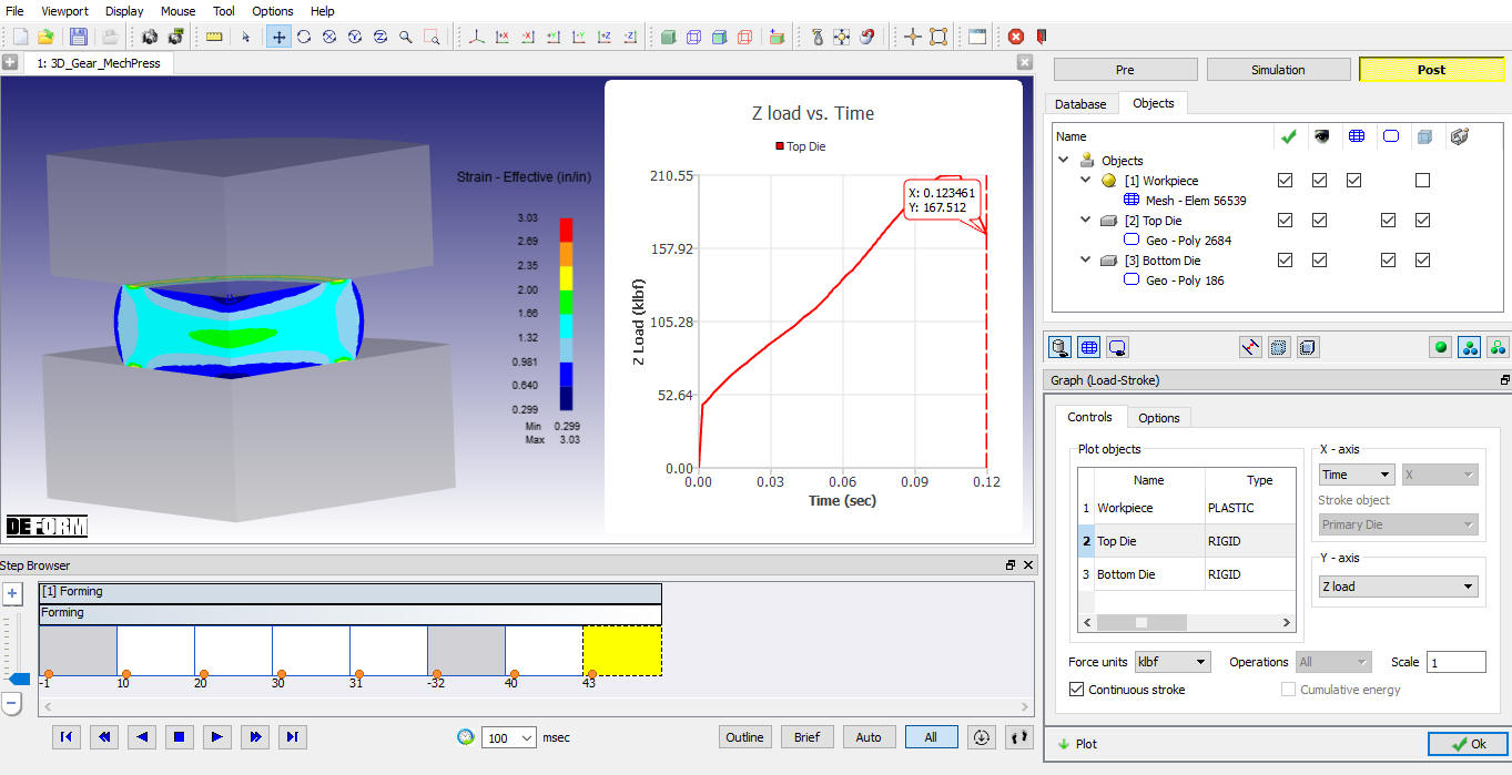
Click on ![]() Graph (Load-Stroke) and plot Time (sec) vs Load (klb) and also plot Time (sec) Vs Speed (in/sec) for top die for Operation 2.
Graph (Load-Stroke) and plot Time (sec) vs Load (klb) and also plot Time (sec) Vs Speed (in/sec) for top die for Operation 2.
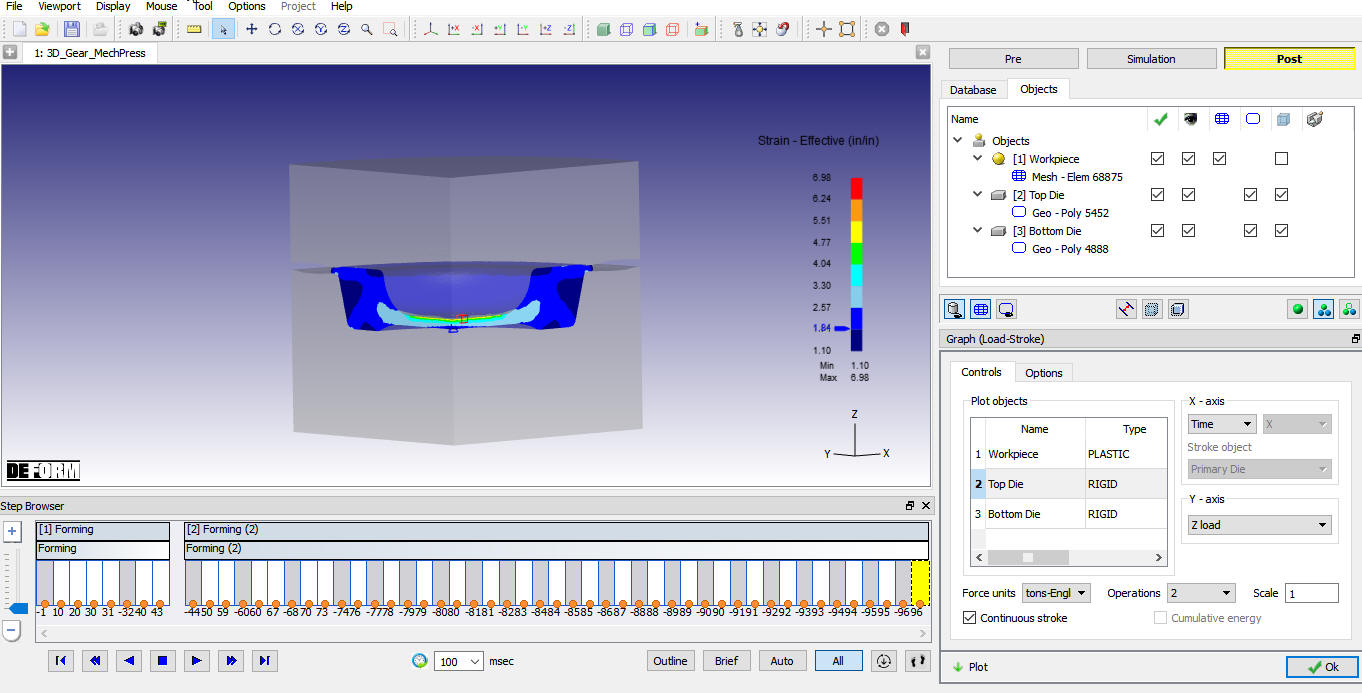
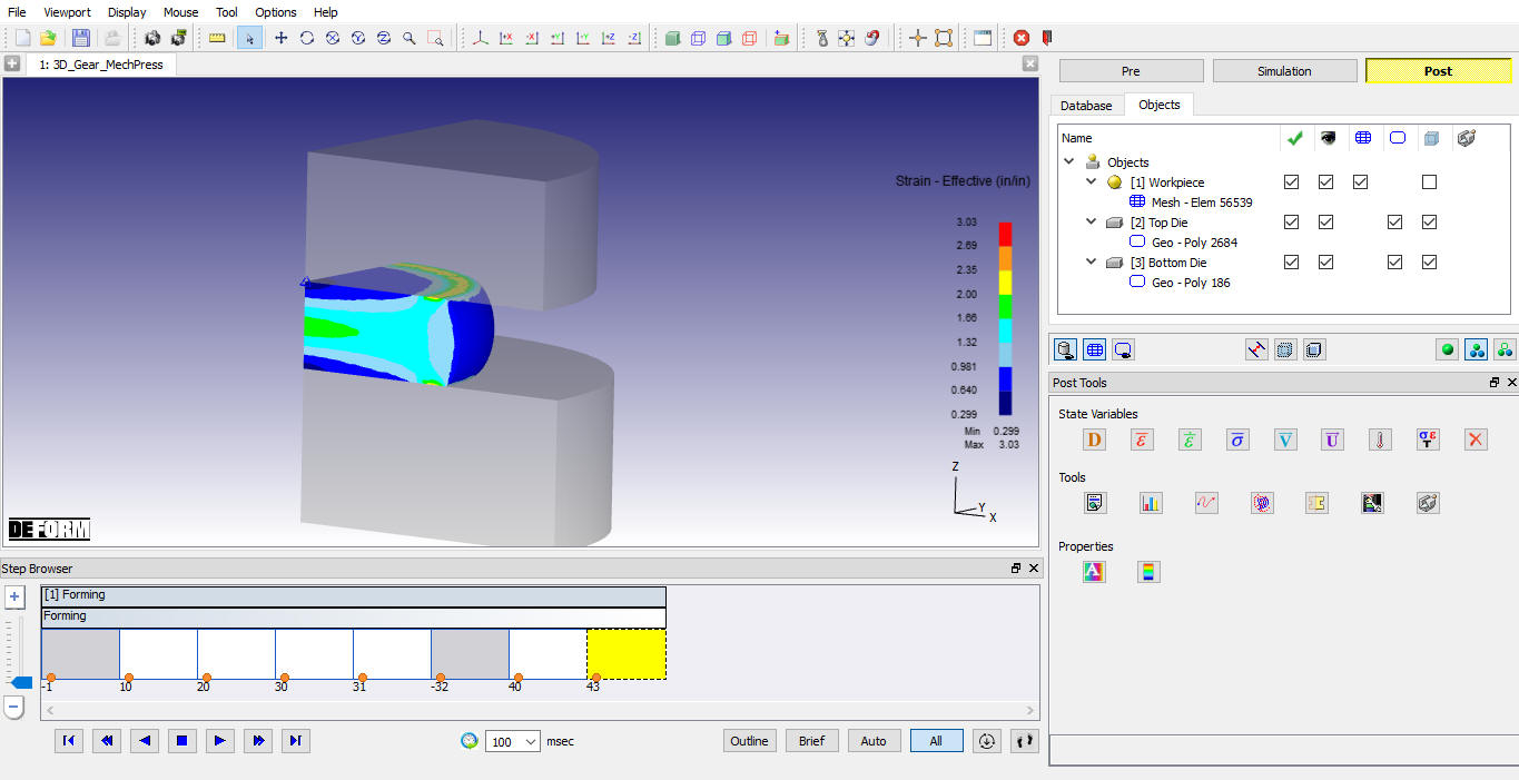
Strain Effective state variable plot for workpiece at 2nd operation last step
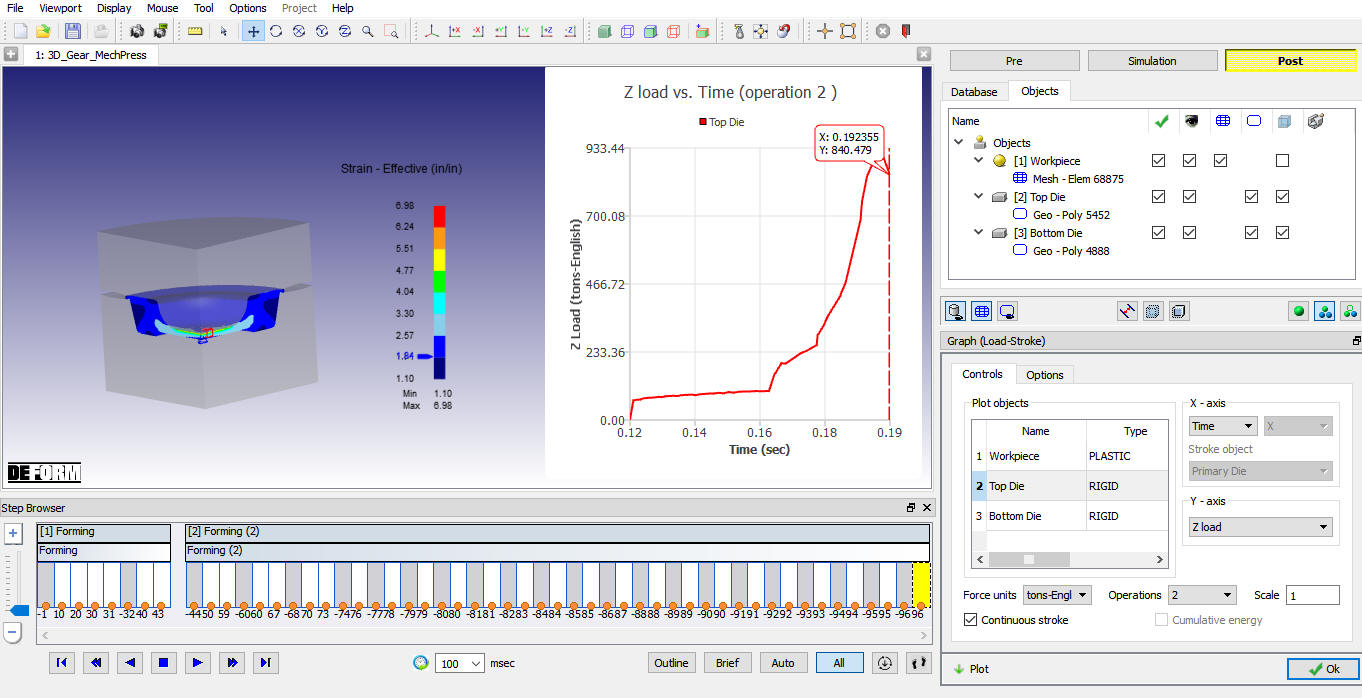
Z-Load v/s Time Graph of Top die in 2nd Operation