Appendix XVII Data Files
Below is a brief list of DAT files that can influence solution behavior. Keeping these DAT files in the problem folder along with DB at the run time gives user additional controls to guide the solution. Brief description of these DAT files and their purpose is indicated here. (This information will be updated from time to time, please contact SFTC for most up to date information about DAT files.)
1. AXIS.DAT
2. DEF_RSE.DAT
3. DEF_GAS.DAT
4. LAY.DAT
5. NBC.DAT
6. PKVEL.DAT
7. STRETCH.DAT
8. SW2SP.DAT
9. DEF_CNT.DAT
10. TSMOOTH.DAT
11. TWEAR.DAT
12. MULTIPLE.DAT
13. DIEGEO.DAT
14. NO_DIEGEO.DAT
15. DEF_ELAON.DAT
16. DEF_PCN.DAT
17. OPT.DAT
18. STRAIN_DST.DAT
19. STRAIN_RATE_DST.DAT
20. LOCAL_REMESH.DAT
21. DEF_LCDSTS.DAT
22. MDIR.DAT
23. DEF_SIM_DIR.DAT
24. SHEET.DAT
25. DEF_INCDISP.DAT
26. DEF_EP.DAT
27. COARSED.DAT
28. DEF_TSHOCK.DAT
29. DEF_ALEC.DAT
30. DEF_ANISOF.DAT (3D)
31. DEF_ADDMPARM.DAT
32. FILE_TO_COPY
AXIS.DAT
This data file allows the user to perform special options on rotating workpiece simulations.
Refer Application XIV: Rotating Workpiece Simulations for more information.
DEF_RSE.DAT
This file allows to enable special features of the Rigid Super-Element scheme to be used during a simulation.
Note : Details provided upon request, please contact support.deform.com
DEF_GAS.DAT
Function: The file DEF_GAS.DAT is a flag used activate gas trapping. Gas trapping can be predicted if the file DEF_GAS.DAT is added to the directory where a simulation is running. The file DEF_GAS.INI is a file output by the program and should not be changed during a simulation. Program will detect the air/oil trap region and apply back pressure based on the trapped volume change. Fig. AXVII.1 shows the air/oil entrapment between the work piece and die. Fig. AXVII.2 shows various deformed shapes of the work piece when there is air/oil entrapment.
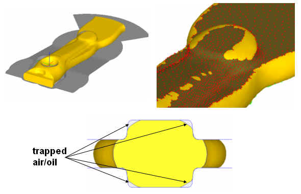
Example showing the air/oil trapped during simulation
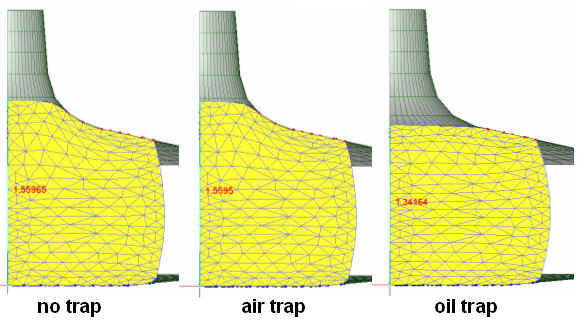
Example of showing various deformed shapes when there is air/oil entrapment
Format:
For entrapment of air
Empty file or a file with
Line 1: 1
For entrapment of lubricant
Line 1: 2
Line 2: Bulk modulus of lubricant (MPa or Ksi)
Refer Appendix XVI: Adding Gas Trap Calculation to a Simulation for more information.
LAY.DAT
This data file is used for mesh consolidation for cogging simulations. This file used to control the element layer consolidation in the older version to increase computing speed for cogging models. After implementation of rigid super elements (RSE) this layer consolidation is not recommended any more for cogging models.
NBC.DAT
Function: Used to add an orthogonal constraint to nodes at a concave die corner. This file allows the user to enable multiple contact conditions on nodes in die corners. This eliminates nodal oscillation in die corners.
Format:
Line 3: A1, A2
Discription:
A1 – starting binding angle
A2 – ending binding angle
If the concave angle is between A1 and A2,the additional constraint is applied.
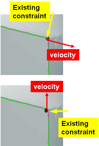
Adding Constraint to Concave Surface
Refer Appendix XV: The Double Concave Corner Constraint for more information.
PKVEL.DAT
Function: Aims to check potential node leaking by comparing the surface node velocity against the theoretical speed calculated by the mass balance equation
Format:
Line 1: I11
Line 2: I21, I22, I23, A21
Line 3 and later: A31, A32
Description:
Line 1: I11 – Optional number, fixed as 6
Line 2: I21 – Total number of cross-section areas to be input
I22 – extrusion direction
I23 – billet object number
A21 – Ram speed
Line 3: A31 – Coordinate of cross-section in the extrusion direction `
A32 – Area of cross section
STRETCH.DAT
This data file is used to activate the check of elemental surface edge stretch/shrinkage and determine if a remeshing is needed. The single-line data file contains the object number, stretch limit and shrink limit. Elemental stretch/shrink is evaluated as the change in edge length divided by the original edge length.
If remeshing needs to be triggered for object #2 when an element edge either shrinks or expands more than 50% from its original size, then the contents of the DAT file should be:
Line 1 - 2, 1.5, 0.5
SW2SP.DAT
This file allows the user to specify the maximum number of elements which the solver can use the Sparse solver. The purpose of this is to control the size of the problem where the sparse solver can be used since it requires more memory than the C-G solver. In the case where sparse solver is not used, the simulation will only use the C-G solver. This option should only be enabled for cases where the C-G solver can be used, i.e. single deforming plastic workpiece with no load controlled dies.
DEF_CNT.DAT
Placing this file in the working folder provides implicit contact controls for EP and plastic models.
Using ‘1’ in the first line of this file means do not adjust the contact nodes, adjust and account for penetration depth only at the next step. Using ‘2’ in the first line means repeat the current step one time once change of penetration depth has been identified at the end of the current step. Using ‘3’ in the first line means repeat the current step twice ..etc. Please note that using any value more than ‘1’ can significantly increase computing time.
TSMOOTH.DAT
Placing this file in the problem folder turns on heat Capacity Smoothing to improve thermal solution behavior using unstructured tet mesh systems. Number ‘2’ in the first line of this file activates this thermal smoothing (for tet mesh systems only)
TWEAR.DAT
Placing this file (no contents) in the problem folder activates simple averaging of tool wear parameters (interface pressure and sliding velocity) on to die surface, thus minimizing the mesh size dependent effects involved with regular shape function based interpolation schemes. This option is made available from DEFORM3D v6.1.1.
MULTIPLE.DAT
Place this file with “Number of Boundaries” in the problem folder allows to keep multiple boundaries after remeshing. The default behavior in 3D without this file is to only keep the biggest boundaries. For example, placing this file with 2 inside for a fracture problem will keep both split objects after fracture.
DIEGEO.DAT
Placing this file (no contents) in the problem folder enables Writing geometry files with marked surface information showing hidden surfaces as seen by FEM at the run time. This file does not effect solution behavior and used only for debugging purpose.
NO_DIEGEO.DAT
Placing this file (no contents) in the problem folder suppress automatic determination of hidden surfaces by FEM procedures.
DEF_ELAON.DAT
Take first iteration of elastic solution for the models with only elastic objects thus saving computing time involved with additional iterations and default convergence checks.
DEF_PCN.DAT
Placing this file in the problem folder limits max number of contacting nodes per substep. Two parameters in the first line of this DAT file A,B are used as controls by FEM procedures. A = max number of contact nodes before substep, B = object number (this file is automatically created by shape rolling template)
OPT.DAT
Placing this file in the problem folder allows different interpolation techniques. Using ‘1’ in the first line of this file, allows using local shape function based interpolation used in the earlier versions of DEFORM3D prior to v6.0. Current default procedures use polynomial based least square fit that more accurately preserves gradient information of the variables being interpolated.
STRAIN_DST.DAT
While GUI has controls that put mesh weights based on strain gradients, placing this file in problem folder (no contents) can force the weights based on the absolute strain magnitudes.
STRAIN_RATE_DST.DAT
While GUI has controls that put mesh weights based on strain rate gradients, placing this file in problem folder (no contents) can force the weights based on the absolute strain rate magnitudes.
LOCAL_REMESH.DAT
Local remeshing control file. Controlling parameters can be defined in GUI and can be saved to this file in the problem folder. Without this file, global remesh procedures take preference, unless extreme meshing conditions arise that require switching to local remesh procedures.
DEF_LCDSTS.DAT
Placing this file in the problem folder triggers coupled die stress analysis. Refer the Application: How to do coupled die stress analysis for 3D models for detailed explanation on this procedures.
MDIR.DAT
Placing this file (no contents) in the problem folder suppresses direct iteration in EP solutions and stay always in newton-raphson iterations. Otherwise default procedures are allowed to switch to approximate direct iterations to overcome convergence issues in a given step.
DEF_SIM_DIR.DAT
Placing this file (Line 1 to indicate folder path to the local simulation engine DEF_SIM.EXE) in the problem folder allows use of local copy of DEF_SIM.EXE in PC environment.
SHEET.DAT
Placing this file (no contents) in the problem folder enables 2nd order nodal coordinate updating accounting for rotational components of velocity field. Default updating procedures use linear updates based on magnitude of nodal velocity, direction and time step size.
DEF_INCDISP.DAT
Placing this file (no contents) in the problem folder activates incremental displacement formulations for EP models. (available from DEFORM v11.0). For EP models default mode without this file is to use velocity based formulations.
DEF_EP.DAT
Placing this file (no contents) in the problem folder allows checking both the force and velocity norms for convergence always. Without this file the procedures are allowed to relax convergence checks on velocity norm in the event of convergence failures in a given step.
COARSED.DAT
Placing this file (uses defaults when empty file is used) in the problem folder allows coarse internal 2d mesh when remesh is triggered. This file is automatically created by ring rolling template for 2D mesh cross section control. The first parameter (first line, integer, default is 5 if not specified) is just to control number of smoothing cycles. Each smoothing, the mesh density of a given internal node/point is averaged by the density of the neighboring points. The boundary density is the same and does not change during smoothing. The larger this first parameter, the deeper the smoothing procedure can affect the resulting meshing. The 2nd parameter (second line, real number) is used to compute the largest element size to be placed inside the part initially. The boundary will have the regular mesh density definition.
DEF_TSHOCK.DAT
Scale up factor can be specified (in the first line of this DAT file) on thermal conductivity, to compute stable time step to minimize numerical oscillations in thermal solution. These numerical oscillations can result from using very small time step, compared to stable time step, and depends on specific heat, thermal conductivity and mesh size.
DEF_ALEC.DAT
Data in this file can be used to override the default convergence criteria in ALE models (e.g Rolling).
(Line #1) First line of this can be used to enable (‘0’ in the first line) or disable automatic stop (‘1’ in the first line).
(Linne #2) Second line can be used to control displacement criteria for convergence defined by DSmax / ELavg (DSmax is maximum displacement compared to previous step at end surface, ELavg is average edge length at beginning surface), 0.01 being default value of this ratio.
(Line #3) Third line can be used to control effective strain stopping criteria defined by (Emax - E1) / Emax (Emax is maximum strain and E1 is maximum strain at end surface), 0.05 being default value of this ratio.
(Line #4) Fourth line can be used to define convergence criteria for ALE thermal solution defined by DTmax which is maximum temperature change compared to previous step at end surface (default being 0.05).
DEF_ANISOF.DAT (3D)
This DAT file provides capability that allows user to model anisotropic friction model. If User’s problem is cross rolling where die surface has a texture/serration in the rolling direction, DEF_ANISOF.DAT can be introduced in the problem folder so that user can define different friction values in global axis system.
(Line #1) Total number of Inter-object relation,
(Line #2) (Inter-object relation) Salve object, Master object (pair of object numbers) of definition #1,
(Line #3) (Directional and friction coef.) C1, C2, C3
(Line #4) (Inter-object relation) Salve object, Master object (pair of object numbers) of definition #2,
(Line #5) (Directional and friction coef.) C1, C2, C3.
DEF_ADDMPARM.DAT
Place this DAT file in working folder, to activate Line scan or Layer by layer scan model.
Without this file, default is Heat source model, and scan path should be input.
Format:
Line 1: 1
Line 2: P1, P2, P3
Line 3: 1
Line 4: Q1, Q2, Q3
Line 5: T1
Line 6: N
Line 7: ANG1, ANG2, ….
Description:
Line 1:
0 = Heat Source scan path model (default)
1 = Layer by Layer scan activation, use fixed time for one layer activation
2 = Layer by Layer scan activation, use Laser speed and deposition size
3 = Line scan activation, use fixed time for one line activation
4 = Line scan activation, use Laser speed and deposition size
Line 2:
P1 = Time for option 1,3. Speed for option 2,4
P2 = Start Angle for scan line from x-axis (0 ~ 360 degree), for option 3,4
P3 = Angle increment for next layer scan, for option 3,4
Line 3:
0 = Initial Temperature (default)
1 = Power Input, Laser
2 = Inherent Strain Model
Line 4:
Power input
Q1 = Power (milli-Watt)
Q2 = efficiency
Q3 = Laser speed
Inherent Strain
Q1,Q2,Q3 = Inherent strain value, ex, ey, ez
Line 5:
T1 = time between layers, DTRECOAT
Line 6:
N = number of angle for line scanning or for inherent scan
Line 7:
ANG1, ANG2, ….. = angle
FILE_TO_COPY
When we run DOE, so far some DAT files has been copied to each run folder. But sometimes we need to copy more DAT files. To copy manually ‘FILE_TO_COPY’ file has been introduced. When this file exists in the main problem folder, during DOE/OPT, files listed in this file will be copied to each run folder.
In DOE/OPT procedure, following DAT files will be copied to each RUN folder from problem directory as default.
AXIS.DAT
DEF_RSE.DAT
DEFORM.PAR
LOCAL_REMESH.DAT
LOC_DEN_CTRL.DAT
SW2SP.DAT
64bit.dat
DEF_SIM_DIR.DAT
DEF_AMG2L.DAT
DEF_AMG3L.DAT