42. Introduction to Ring Rolling
Ring Rolling Operation template setup is designed for guiding user to setup different types of typical Ring Rolling processes. A typical Ring Rolling setup consists of Ring(workpiece), Pressure Roll, Mandrel and Axial rolls (2 nos) and looks like as shown in Fig. 42.1. Ring Rolling template can also be used to setup Railroad Wheel Rolling process, for Railroad wheel Rolling one Tread Roll, 2 Web Rolls and 2 Axial rolls are allowed as shown in Fig. 42.2. Ring Rolling process can be setup in batch mode or in interactive mode along with Heat Transfer and Forming operations. The workpiece object can be passed from other operations to Ring Rolling template where necessary mesh settings and process settings can be made to simulate the process.
Only brick type mesh can be used for Workpiece/ Ring and Dies. As the simulation runs the workpiece expands and message file is updated with information like current maximum radius, current angle of rotation and total number of revolutions..etc. Simulation can also be stopped based on the workpiece diameter. Template has additional options to apply constraints on the workpiece displacement to bring stability to the workpiece during simulation.
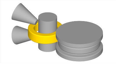
Ring Rolling setup
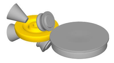
Railroad Wheel Rolling setup
Ring Rolling Operation setup
Ring Rolling operation is designed based on the following system (applicable to Rail Wheel Rolling also):
-
Object 1 is the deforming object.
-
The workpiece or rolling stock is always defined as object 1 and then followed by defining rolls.
-
The order of the objects should be maintained in the Ring Rolling/ Rail Wheel rolling setup
-
The rolling stock is of rigid-plastic type.
-
The rolls are rigid objects during for the rolling simulations.
-
The rolling axis is in the Z direction.
The operation tree of a Ring Rolling setup is shown in Fig. 42.3.
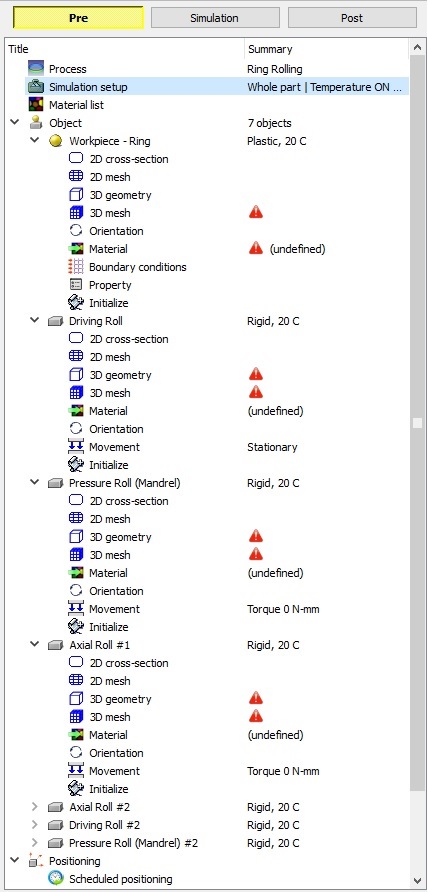
Object tree for Ring Rolling setup
Related Topics: