ALE Shape Rolling Lab1(using 2.5 D Mesh)
In this lab we are setting up simple ALE rolling operation using the 2.5 D simulation result mesh output.
1.1. Creating a New problem
1.2. Adding Shape Rolling operation
1.3. Set process conditions
1.4. Define Workpiece
1.5. Defining Grooves
1.6. Pass Table
1.7. Running 2.5 D simulation
1.8. 3D Setup
1.9. Rolling pass operation
1.10. Stand Table
1.11. Defining Contact Relations
1.12. Simulation Controls page
1.13. Generate Database
1.14. Running Simulation
1.15. Post Processing
Creating a New problem
On a Windows machine , go to the ![]() button select DEFORM-v1x.xxx (.xxx indicates version number E.g. v14.0.2) and select DEFORM GUI Main vxx.xx from the menu. The DEFORM GUI Main window will appear.
button select DEFORM-v1x.xxx (.xxx indicates version number E.g. v14.0.2) and select DEFORM GUI Main vxx.xx from the menu. The DEFORM GUI Main window will appear.
Create a new problem either by selecting File![]() **New Problem** or by clicking the New Problem
**New Problem** or by clicking the New Problem ![]() icon. The Problem Setup window will appear as shown in Fig. ALEL1.1. Select “ Integrated Manufacturing Process “ radio button and Unit system as “SI “ using radio button. Define Problem Name as “MO_ALE_LAB1 “ and make sure the “Show option dialog ” check box is turned on (if we do not turn on the “Show option dialog ” check box, then we will not get the New Project dialog in MO UI). Then click on
icon. The Problem Setup window will appear as shown in Fig. ALEL1.1. Select “ Integrated Manufacturing Process “ radio button and Unit system as “SI “ using radio button. Define Problem Name as “MO_ALE_LAB1 “ and make sure the “Show option dialog ” check box is turned on (if we do not turn on the “Show option dialog ” check box, then we will not get the New Project dialog in MO UI). Then click on ![]() button to open a new Problem using the Deform Integrated Manufacturing Process.
button to open a new Problem using the Deform Integrated Manufacturing Process.
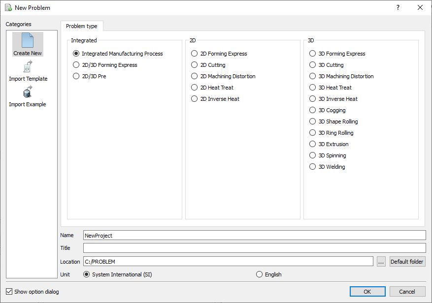
Problem type selection window
Multiple operation wizard will open with the New Project dialog as shown in Fig. ALEL1.2., at this point user will be prompted to specify a project name (system will create a separate folder with this project name) and title for this session. In this session we will use ‘MO_ALE_LAB1 ’ as the project name. 3D Shape Rolling operation can also be added in “New Project” dialog (see Fig. ALEL1.2.)), in this lab we will add Shape rolling operation from Explorer operation list, so do not check “First operation” check box and “ Shape Rolling” operation in “New Project” dialog. Click on ![]() to continue to open the operation.
to continue to open the operation.
Adding Shape Rolling operation
Add one Shape Rolling operation from the Explorer Operations list. Operation can be added by clicking on Shape Rolling operation ![]() button or user can also add by drag and drop into the Operation Editor (see Fig. ALEL1.3.).
button or user can also add by drag and drop into the Operation Editor (see Fig. ALEL1.3.).
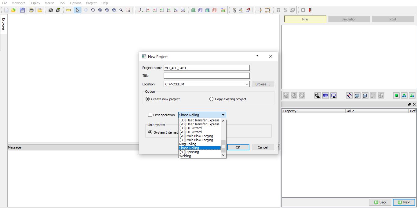
MO Wizard new Project opening window
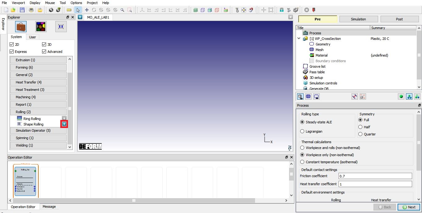
Adding Shape Rolling Operation from explorer
Set process conditions
Select the rolling type as “Steady-State ALE and symmetry type as Full , as we will be setting up complete object. As we are not interested in temperature gradient in rolls, select the “Workpiece only (non-isothermal) “ option. Define the friction coefficient value as 0.7 and heat transfer coefficient value as 11 as shown in Fig. ALEL1.4. Click on ![]() to WP_CrossSection page.
to WP_CrossSection page.
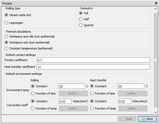
Process page
Define Workpiece
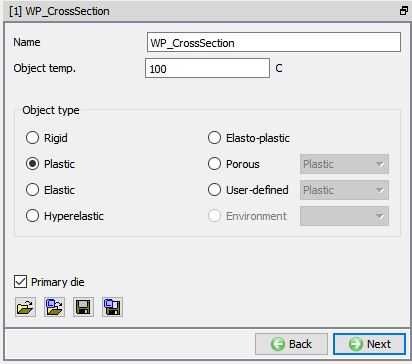
In WP_CrossSection window keep the object type as ‘Plastic ’ and specify workpiece temperature as 100°C (see Fig. ALEL1.5.). Click on ![]() to continue.
to continue.
Workpiece Object Definition
Create Workpiece Geometry
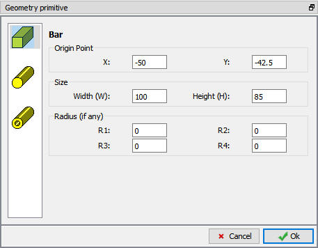
To create a rectangular bar geometry for workpiece, in Geometry page select Define Primitive. From primitive geometry window select bar and define the parameters Origin Point = (-50, -42.5), Width W = 100mm and Height H = 85mm and click to close. A rectangular bar is created as shown in Fig. ALEL1.6. Click on ![]() to Mesh.
to Mesh.
Define Primitive
Generate Workpiece mesh
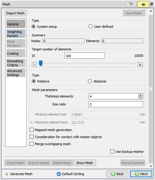
Generate the workpiece mesh with default number of elements and settings (see Fig. ALEL1.7.). Click on ![]() .
.
Workpiece mesh generation
Assigning Workpiece material
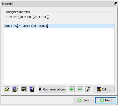
To assign material for workpiece, select the material ‘AISI-1045’ from material window. This can be done as shown in Fig. ALEL1.8. Click on ![]() until Groove list page.
until Groove list page.
Assigning material for Workpiece
Defining Grooves
In Groove List page, we can add grooves by clicking on the ![]() button. Click
button. Click ![]() once to add one groove (see Fig. ALEL1.9), we will be using same groove for top and bottom roll.
once to add one groove (see Fig. ALEL1.9), we will be using same groove for top and bottom roll.
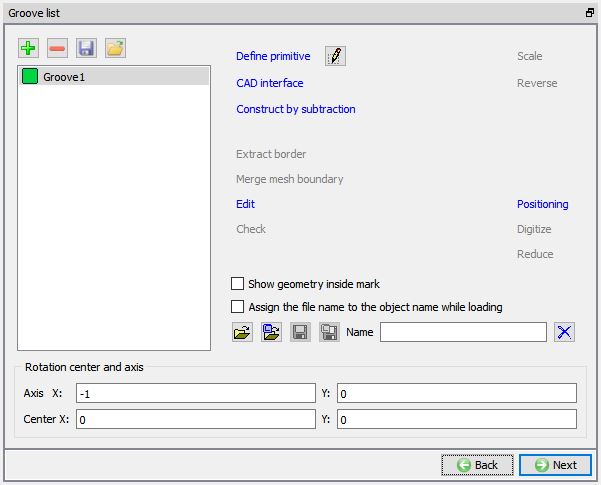
Groove list page
Defining Groove1
Select the First groove and click on ![]() . Roll Groove Primitive page will be opened, select Flat rolls. For roll geometry, Define width (W) as 120, radius (r1) as 5 and Roll Radius (RR) as 100 as shown in Fig. ALEL1.10. Click
. Roll Groove Primitive page will be opened, select Flat rolls. For roll geometry, Define width (W) as 120, radius (r1) as 5 and Roll Radius (RR) as 100 as shown in Fig. ALEL1.10. Click ![]() to close. Click on
to close. Click on ![]() to Pass page.
to Pass page.
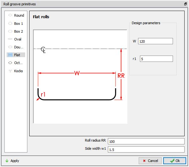
Groove Geometry defining
Pass Table
In pass table, we will assign the groove geometries for top roll.
Under Pass1, select the Groove 1 for Top roll, system will copy the top roll geometry for bottom roll bottom roll if asymmetric rolling check box is not checked.
Define the Roll speed (rpm) as 50, Roll gap (mm) as 80 and Environment temperature as 20C. Leave other settings as default. Use Default Number of sections as 20 as shown in Fig. ALEL1.11.
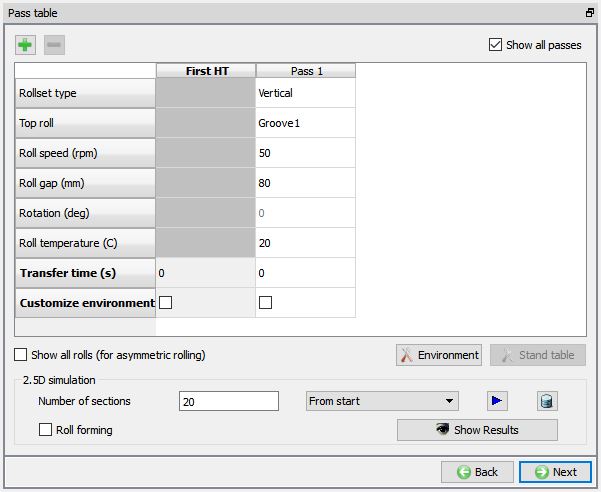
Pass Table
Running 2.5 D simulation
Click on ![]() button, when we click on
button, when we click on ![]() button 2.5D simulation will start to simulate and message file is updating as the simulation progress (see Fig. ALEL1.12.). After completion of simulation click
button 2.5D simulation will start to simulate and message file is updating as the simulation progress (see Fig. ALEL1.12.). After completion of simulation click ![]() to close.
to close.
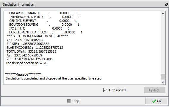
2.5 D Simulation message file.
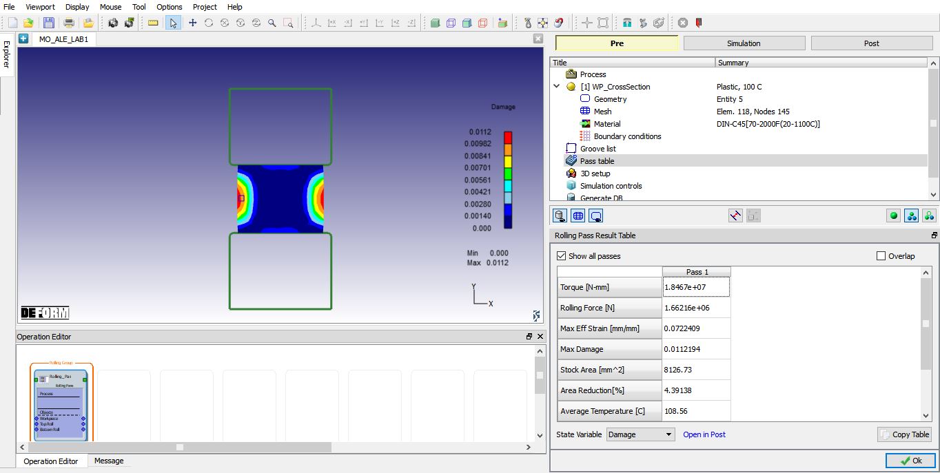
To view the 2.5 D simulation results, click on ![]() button. We will observe the Result table as shown in Fig. ALEL1.13. Also we can plot state variable using state variable pull down menu and selecting respective state variable. Click
button. We will observe the Result table as shown in Fig. ALEL1.13. Also we can plot state variable using state variable pull down menu and selecting respective state variable. Click ![]() to close the Results page. Click on
to close the Results page. Click on ![]() to setup 3D objects for workpiece and Rolls.
to setup 3D objects for workpiece and Rolls.
2.5 D simulation result page
3D Setup
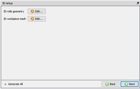
Geometry and mesh settings of 3D Rolls and workpiece are available in this page to setup 3D models. (See Fig. ALEL1.14.)
3D Setup page
3D Rolls geometry setup
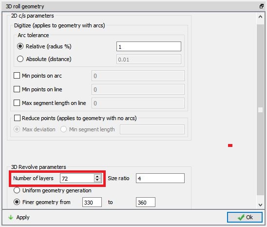
Select the ![]() button of 3D rolls geometry, 3D roll geometry settings window will open, In 3D rolls Geometry settings window, define the number of layers for rolls as 72 and select the ‘Finer geometry from’ option to generate at the contact region with workpiece. Click on
button of 3D rolls geometry, 3D roll geometry settings window will open, In 3D rolls Geometry settings window, define the number of layers for rolls as 72 and select the ‘Finer geometry from’ option to generate at the contact region with workpiece. Click on ![]() button to generate rolls with new settings. Click on
button to generate rolls with new settings. Click on ![]() button to close the 3D rolls Geometry settings window.
button to close the 3D rolls Geometry settings window.
3D Roll Geometry settings page
3D Workpiece setup using 2.5 D result
In this lab we will be using the results from 2.5D simulation which are already available from 1.7.Section, to generate 3D mesh for workpiece.
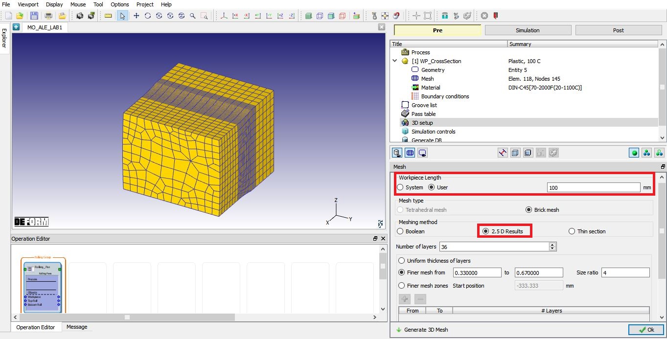
Select the ![]() button of 3D Workpiece, 3D Workpiece mesh settings window will open. Select the user radio button for Workpiece Length and define the length as 100mm, Select Meshing method as 2.5D Results, define Number of Layers as 36 and select the finer mesh from 0.333 to 0.6667 (see Fig. ALEL1.16.). Then click on
button of 3D Workpiece, 3D Workpiece mesh settings window will open. Select the user radio button for Workpiece Length and define the length as 100mm, Select Meshing method as 2.5D Results, define Number of Layers as 36 and select the finer mesh from 0.333 to 0.6667 (see Fig. ALEL1.16.). Then click on ![]() . Click
. Click ![]() to close the Workpiece mesh settings window. Click on
to close the Workpiece mesh settings window. Click on ![]() to continue.
to continue.
3D Workpiece mesh settings page
Now save the project and select the Rolling Pass operation in operation editor.
Rolling pass operation
Select the Rolling Pass operation in the operation editor.
Rolling pass operation
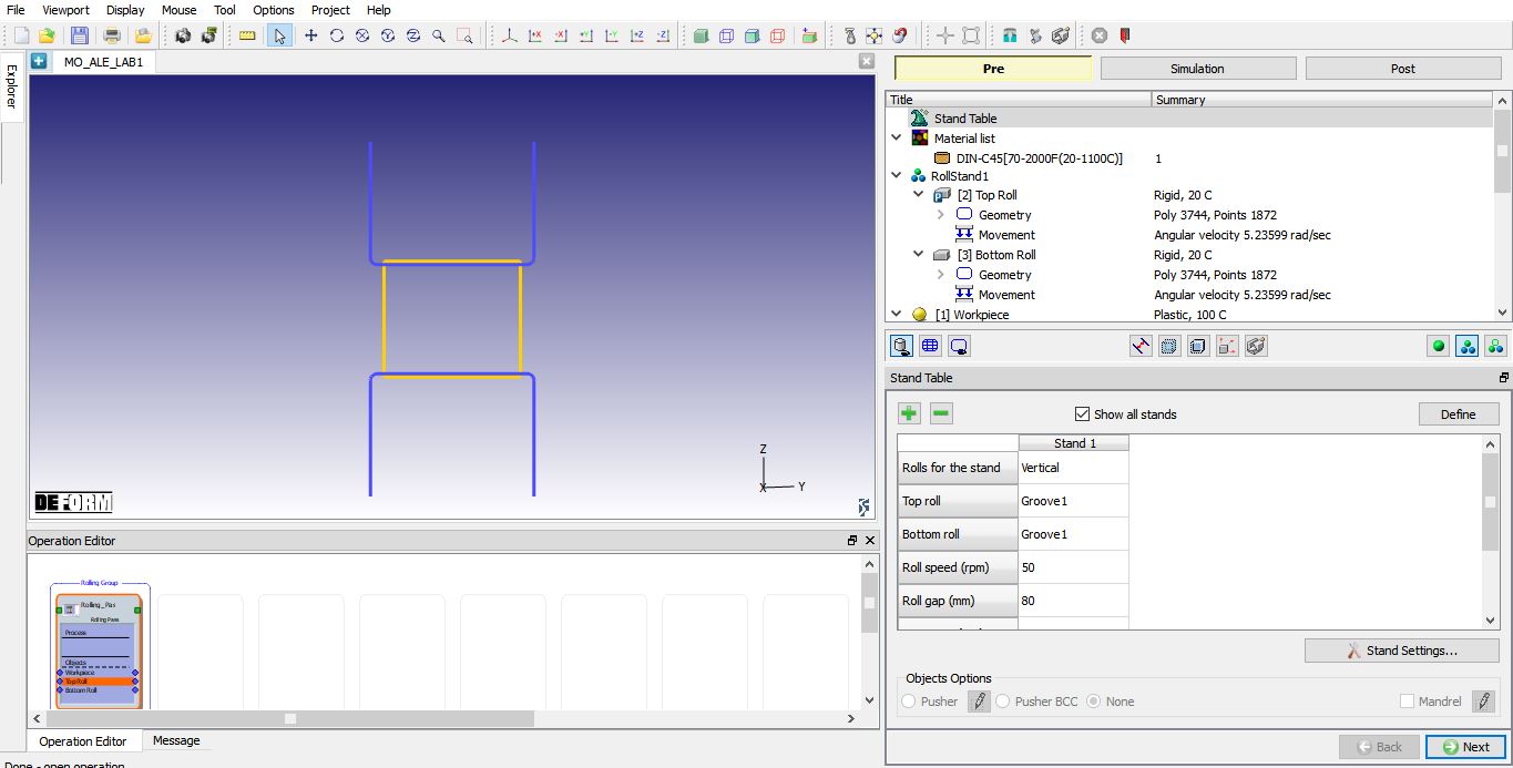
Stand Table
As you select the Rolling Pass operation stand table page will appear as shown in Fig. ALEL1.17. In this lab we will not be using Tables and we will keep temperature for Rolls as 20°C. So click on ![]() until Contact page.
until Contact page.
Defining Contact Relations
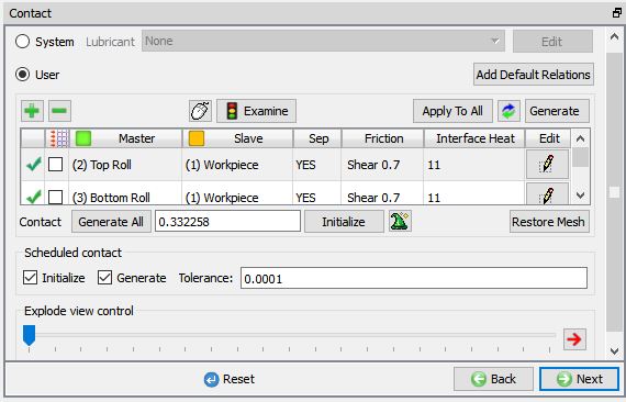
In the Contact relations page, master-slave relations will be automatically added. Define the shear friction as 0.7 and interface heat transfer coefficient as 11 (see Fig. ALEL1.18.). Click the ![]() to determine an intelligent contact tolerance and then click on
to determine an intelligent contact tolerance and then click on ![]() button to generate contacts between objects. Click
button to generate contacts between objects. Click ![]() button.
button.
Contact Relations generation
Simulation Controls page
In simulation controls page set Time steps as 5000 for this simulation with a step increment to save as 10 and Time per step as 0.001 sec. From DEFORM v12, ALE steady state convergence stopping criteria option has been added in Step controls, user can define ALE steady state stopping criteria for ALE rolling operation. In this lab we will use default values, click on ![]() to generate DB.
to generate DB.
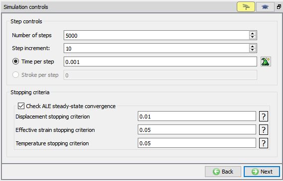
Simulation controls
Generate Database
In the database generation stage user can check the data required for the analysis and proceed to generate the database (see Fig. ALEL1.20.).
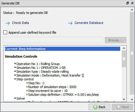
Database Generation
Running Simulation
Once the database has been generated switch to the Simulation mode by clicking on ![]() button above the operation tree. Click on the
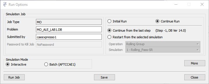
button above the operation tree. Click on the ![]() action label to open the Run Options dialog as shown in Fig. ALEL1.21. Use the default ContinueRun option to select “Continue from the last step ” (from step -1) option and then select the Simulation mode as Interactive radio button. Click on
action label to open the Run Options dialog as shown in Fig. ALEL1.21. Use the default ContinueRun option to select “Continue from the last step ” (from step -1) option and then select the Simulation mode as Interactive radio button. Click on ![]() button to run the simulation.
button to run the simulation.
To define MPI settings, click on ![]() button, Run Options window will expand and displays options to define MPI settings for simulation (max number of processors that can be defined depend on your 3D MPI license).
button, Run Options window will expand and displays options to define MPI settings for simulation (max number of processors that can be defined depend on your 3D MPI license).
Run Options dialog
Monitor the progress of the simulation by looking at the Simulation Message and Simulation Log tab, making sure that the ![]() option is checked. User can view the rolling process as the simulation proceeds from Simulation graphics
option is checked. User can view the rolling process as the simulation proceeds from Simulation graphics
Simulation will stop after reaching steady state with a below message in Message file.
” PROGRAM STOPPED!
CURRENT ROLLING PASS HAS REACHED STEADY-STATE CONDITIONS “
Post Processing
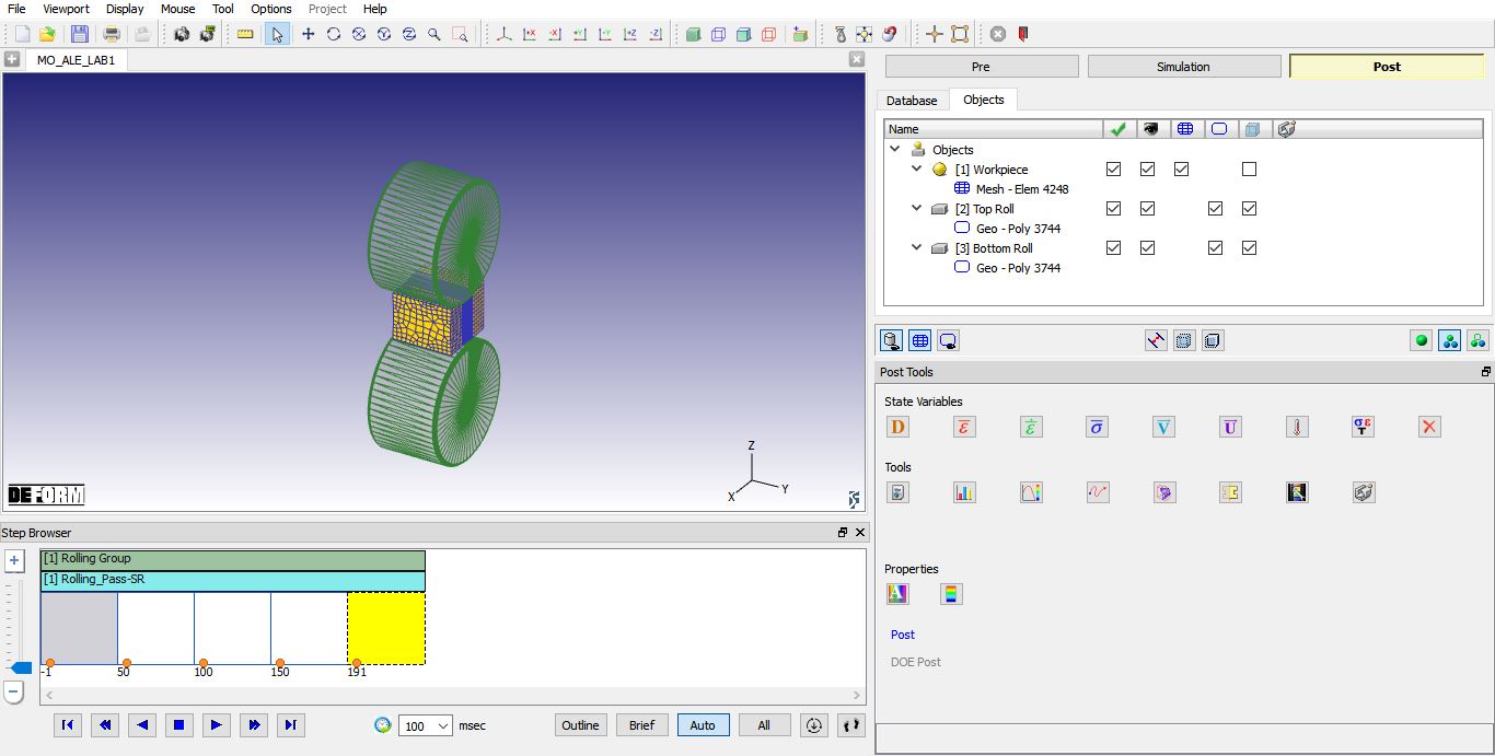
After the simulation has completed, click on ![]() tab, MO post processor will open (as shown in Fig. ALEL1.22.).
tab, MO post processor will open (as shown in Fig. ALEL1.22.).
MO Post mode
Go to last step, Plot Strain - Effective and Stress Max principal state available and observe the state variable distribution (see Fig. ALEL1.23. and Fig. ALEL1.24.).
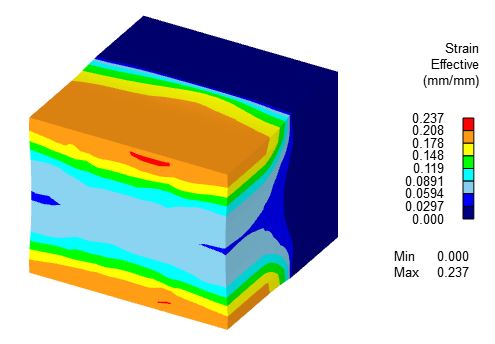
Strain - Effective Plot
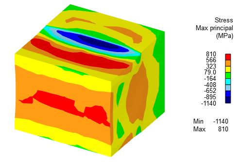
Stress Max Principal Plot