2D Fracture
Setting up fracture simulation in DEFORM-2D
Introduction
To activate fracture, the following actions must be taken:
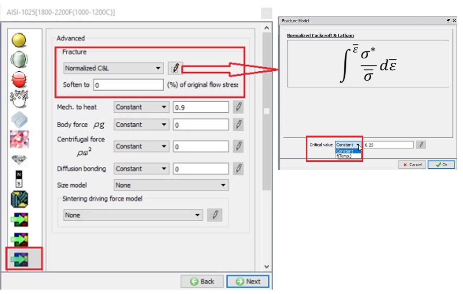
- Choose the Damage model to be used and select a critical value. This damage model is chosen in the material properties
 Advanced dialog. Please note that starting from DEFORM 2DV91, user is given more controls to set the degree of softening on crossing critical damage value. For example, when user selects ‘Soften to 10 % of original flow stress, once a material point crosses critical damage value load carrying capacity will drop by 90% hence triggering localized material flow.
-
Set the number of fracture elements under Object Properties
Fracture(FRCMOD) for the object that will have the fracture occur. The recommended setting is to set fracture elements to a value between 2 and 5. (This data should be set at 0, if user sets damage based on softening as a % of flow stress reduction which is explained in the previous section). This setting will delete elements after the set number of elements is above the critical damage value. -
Refine the mesh in the region where the fracture will occur. The mechanics of fracture may involve a high gradient of damage, strain and other variables. A fine mesh aids in properly capturing this behavior.
Lab: Setting up fracture with element deletion in DEFORM-2D
1.2.1. Creating New Problem
1.2.2. Adding 2D forming operation
1.2.3. Defining Geometry Type
1.2.4. Setting up simulation mode
1.2.5. Load material into material list
1.2.6. Adding objects
1.2.7. Defining Sheet object
1.2.8. Defining Punch object
1.2.9. Defining Die object
1.2.10. Generation mesh for Sheet
1.2.11. Defining Blank Holder object
1.2.12. Positioning objects
1.2.13. Defining inter-object relations
1.2.14. Defining stopping controls
1.2.15. Defining step controls
1.2.16. Generating Database
1.2.17. Running Options
1.2.18. Post Processing
Creating New Problem
On a Windows machine, go to the ![]() button select DEFORM-v1x.xxx (.xxx indicates version number E.g. v14.0.2) and select DEFORM GUI Main v1x.x from the menu. The DEFORM GUI Main window will appear
button select DEFORM-v1x.xxx (.xxx indicates version number E.g. v14.0.2) and select DEFORM GUI Main v1x.x from the menu. The DEFORM GUI Main window will appear
New Problem page
Create a new problem either by selecting File![]() **New Problem** or by clicking the New Problem
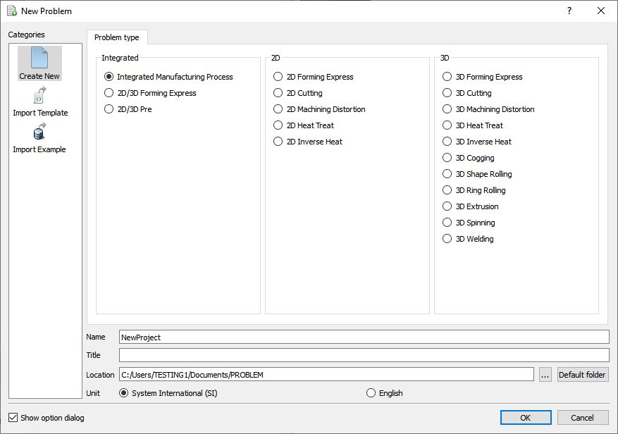
**New Problem** or by clicking the New Problem ![]() icon. The Problem Setup window will appear. Select “Integrated Manufacturing Process “ radio button and unit system as “SI “ radio button in Unit as shown in Fig. 2DFRCL1.1. Define Problem Name as “2DFracture “ and make sure the “Show option dialog” check box is turned on (if we do not turn on the “Show option dialog ” check box, then we will not get the New Project dialog in MO UI). Then click on
icon. The Problem Setup window will appear. Select “Integrated Manufacturing Process “ radio button and unit system as “SI “ radio button in Unit as shown in Fig. 2DFRCL1.1. Define Problem Name as “2DFracture “ and make sure the “Show option dialog” check box is turned on (if we do not turn on the “Show option dialog ” check box, then we will not get the New Project dialog in MO UI). Then click on ![]() button to open a new Problem using the Deform Integrated Manufacturing Process.
button to open a new Problem using the Deform Integrated Manufacturing Process.
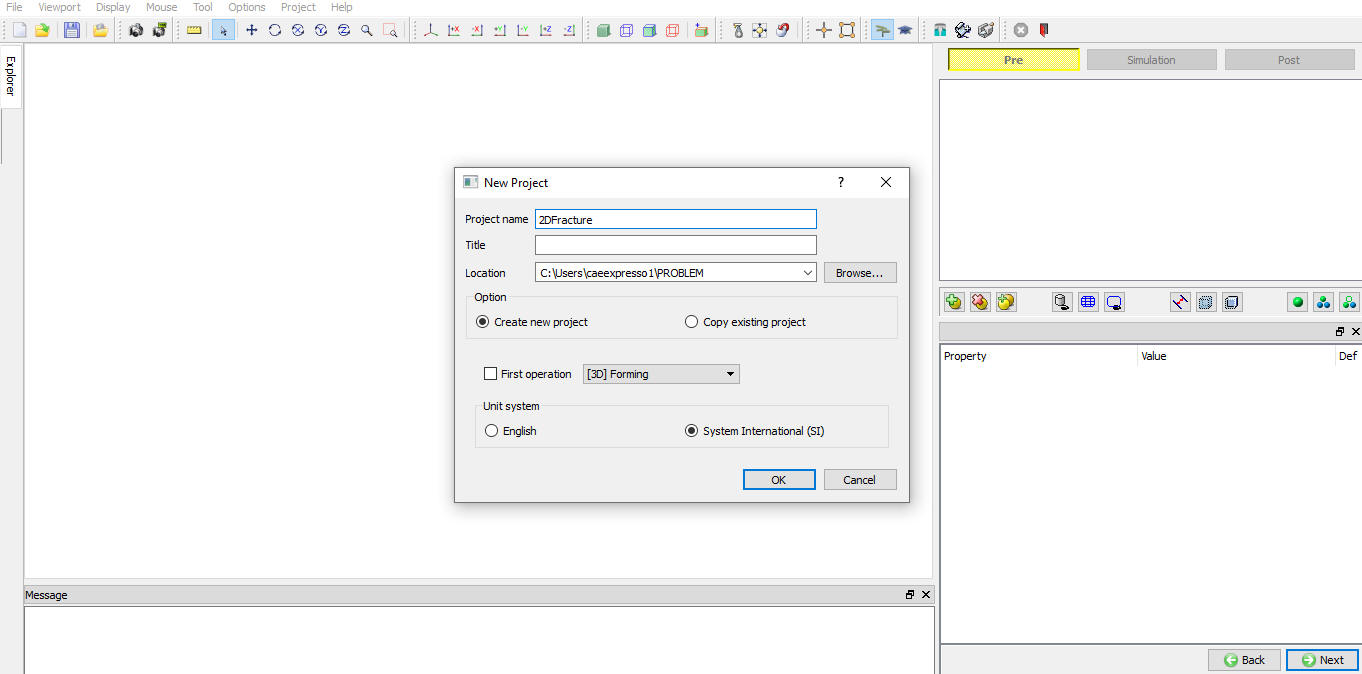
Multiple operation wizard will open with the New Project dialog, at this point user will be prompted to specify a project name (system will create a separate folder with this project name) and title for this session. In this session we use “2DFracture “ as the project name. Click on ![]() to continue to open the operation. MO wizard will open (see Fig. 2DFRCL1.2.).
to continue to open the operation. MO wizard will open (see Fig. 2DFRCL1.2.).
MO Wizard New Project Window
Adding 2D forming operation
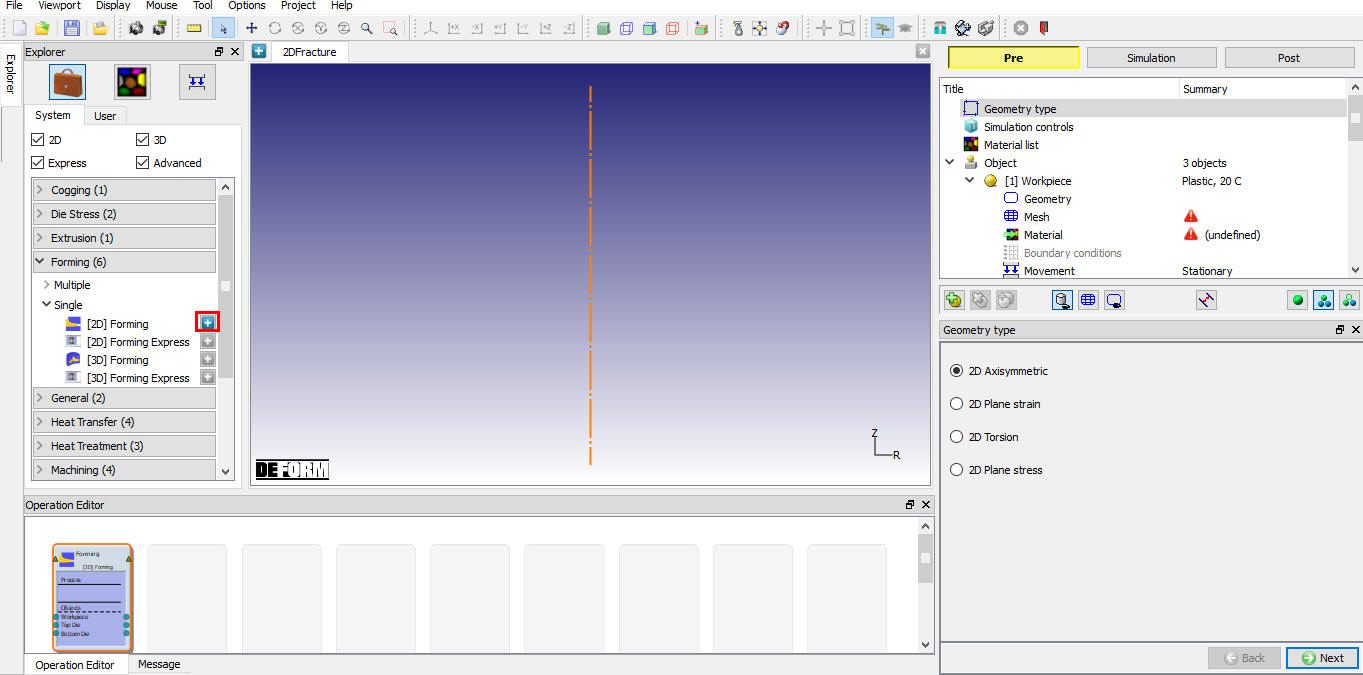
Multiple Operation wizard will open new project. Add one Forming operation from Explorer Operations list by clicking ![]() button as shown in Fig. 2DFRCL1.3.
button as shown in Fig. 2DFRCL1.3.
Adding 2D Forming operation into Operation Editor
Defining Geometry Type
In this lab, we will be using Axisymmetric geometries, so select 2D Axisymmetric radio button from geometry type page as shown in Fig. 2DFRCL1.4. Click ![]() to simulation controls page.
to simulation controls page.
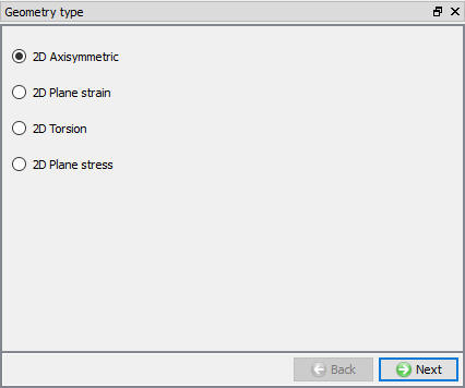
Axisymmetric Geometry type selection
Setting up simulation mode
In this lab we will be using Deformation. So, in Simulation controls uncheck the Heat transfermode check box (See Fig. 2DFRCL1.5.). Then Click ![]() to Material list page.
to Material list page.
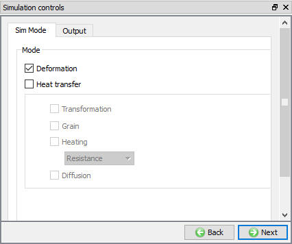
Simulation mode selection
Loading material into material list
Material list page will open, load the material keyword file CuZn15.Key from /2D/Labs/Fracture folder as shown in Fig. 2DFRCL1.6. Click ![]() to Objects page.
to Objects page.
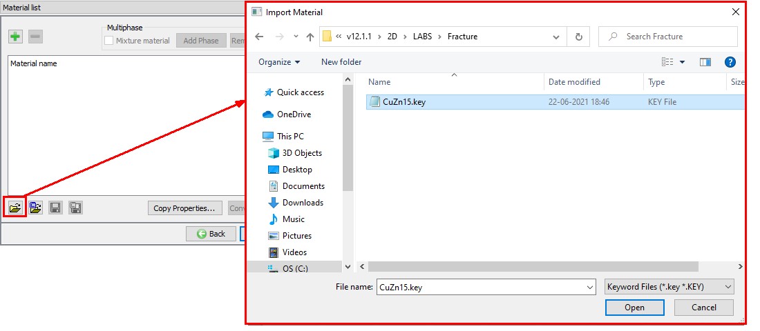
Loading Material into Material list
Adding objects
For this operation we require four objects, if there aren’t already three objects, add four objects by clicking the ![]() button. Four objects will be added as Workpiece, Top Die, Bottom Die and Object 4 as shown in Fig. 2DFRCL1.7. Click
button. Four objects will be added as Workpiece, Top Die, Bottom Die and Object 4 as shown in Fig. 2DFRCL1.7. Click ![]() to Workpiece page.
to Workpiece page.
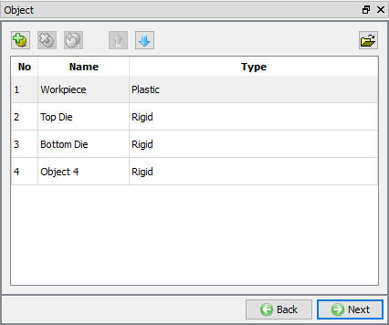
Adding Objects
Defining Sheet object
Defining object data of Sheet
In Workpiece Object page, change the object name to Sheet and object type as Plastic. Define object temperature as 20 °C (see Fig. 2DFRCL1.8.). Click ![]() to Geometry page.
to Geometry page.

Workpiece object page
Defining Sheet Geometry
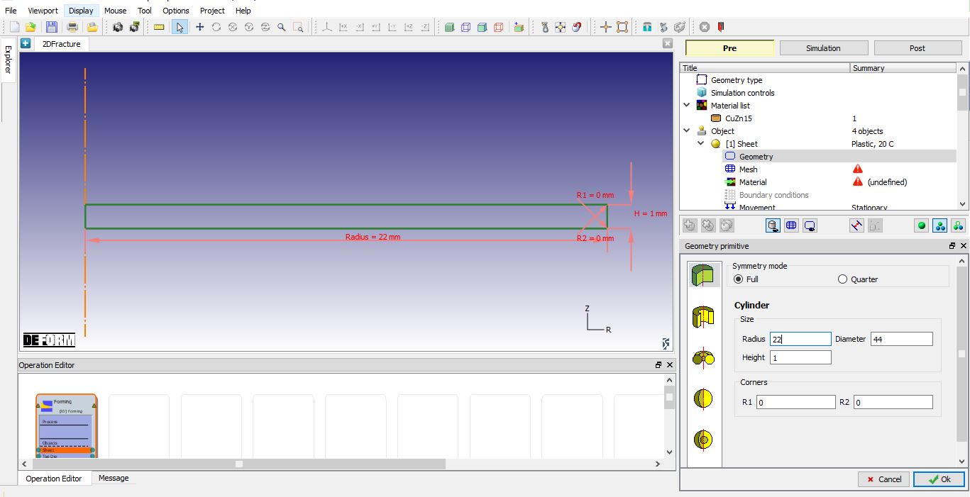
Click on ![]() , select Cylinder and define Radius as 22, Height as 1 as shown in Fig. 2DFRCL1.9. Click on
, select Cylinder and define Radius as 22, Height as 1 as shown in Fig. 2DFRCL1.9. Click on ![]() button to accept all the changes and go back to the Geometry definition. Sheet geometry is created. Click on
button to accept all the changes and go back to the Geometry definition. Sheet geometry is created. Click on ![]() until material page, we will generate mesh after defining the dies.
until material page, we will generate mesh after defining the dies.
Defining Sheet Geometry
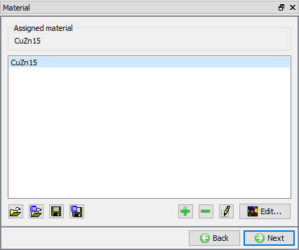
Assigning material to Sheet
Click on the CuZn15 in the material window to assign the material to Sheet as shown in Fig. 2DFRCL1.10. Click ![]() to Property page.
to Property page.
Assigning material to Sheet
Defining Fracture elements for Sheet
Click on Fracture tab, select “Fracture element deletion “ type from pulldown menu and define Fracture elements value as 4 as shown in Fig. 2DFRCL1.11., when 4 neighbouring elements reach critical damage then that element will be deleted. Click ![]() to Top die page.
to Top die page.
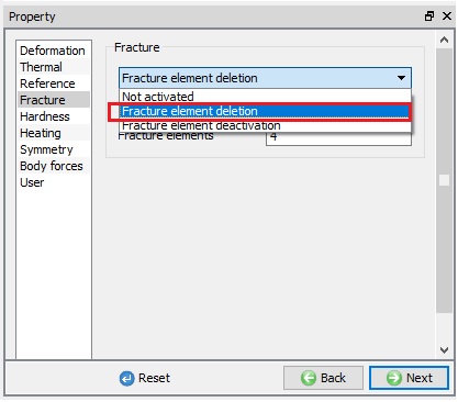
Defining fracture elements
Defining Punch object data
Change the object name to Punch. Use default temperature and select the object type as Rigid as shown in Fig. 2DFRCL1.12. Click ![]() button to define geometry.
button to define geometry.

Top die object page
Importing the Punch geometry
Click the ![]() (Load geometry from a file) button and import the file “ punch.geo ” from /2DLabs/Fracture folder as shown in Fig. 2DFRCL1.13. Click
(Load geometry from a file) button and import the file “ punch.geo ” from /2DLabs/Fracture folder as shown in Fig. 2DFRCL1.13. Click ![]() until Movement page.
until Movement page.
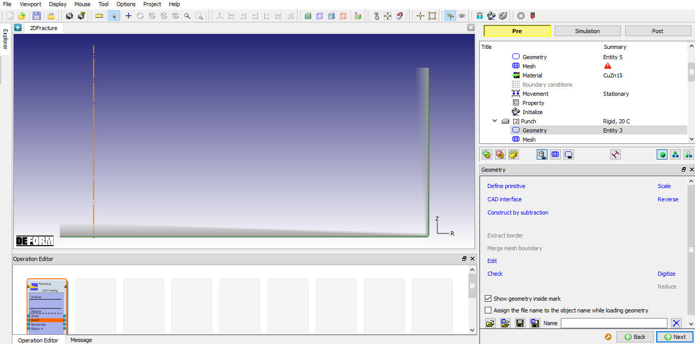
Importing the punch geometry
Assigning Movement for Punch
We will define constant speed of 1 mm/sec in -Y direction as shown in Fig. 2DFRCL1.14. Click ![]() to Bottom Die page
to Bottom Die page
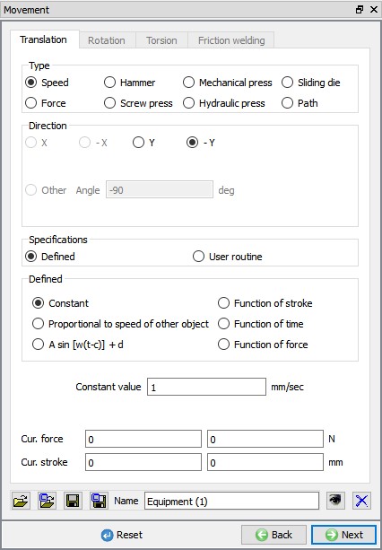
Defining Punch Movement
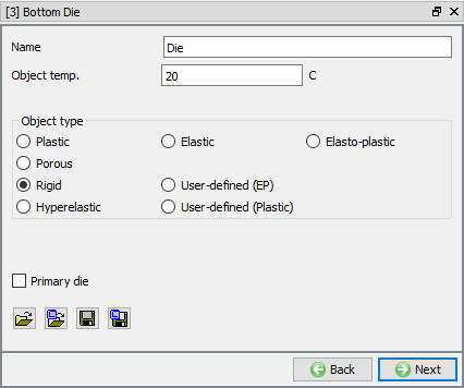
Defining Die object data
Change the object name of Bottom Die to Die. Use default temperature and select the object type as Rigid as shown in Fig. 2DFRCL1.15. Click ![]() button to define Geometry.
button to define Geometry.
Die object page
Importing the Die geometry
Click the ![]() (Load geometry from a file) button and import the file “ die.geo ” from /2D/Labs/Fracture folder as shown in Fig. 2DFRCL1.16.
(Load geometry from a file) button and import the file “ die.geo ” from /2D/Labs/Fracture folder as shown in Fig. 2DFRCL1.16.
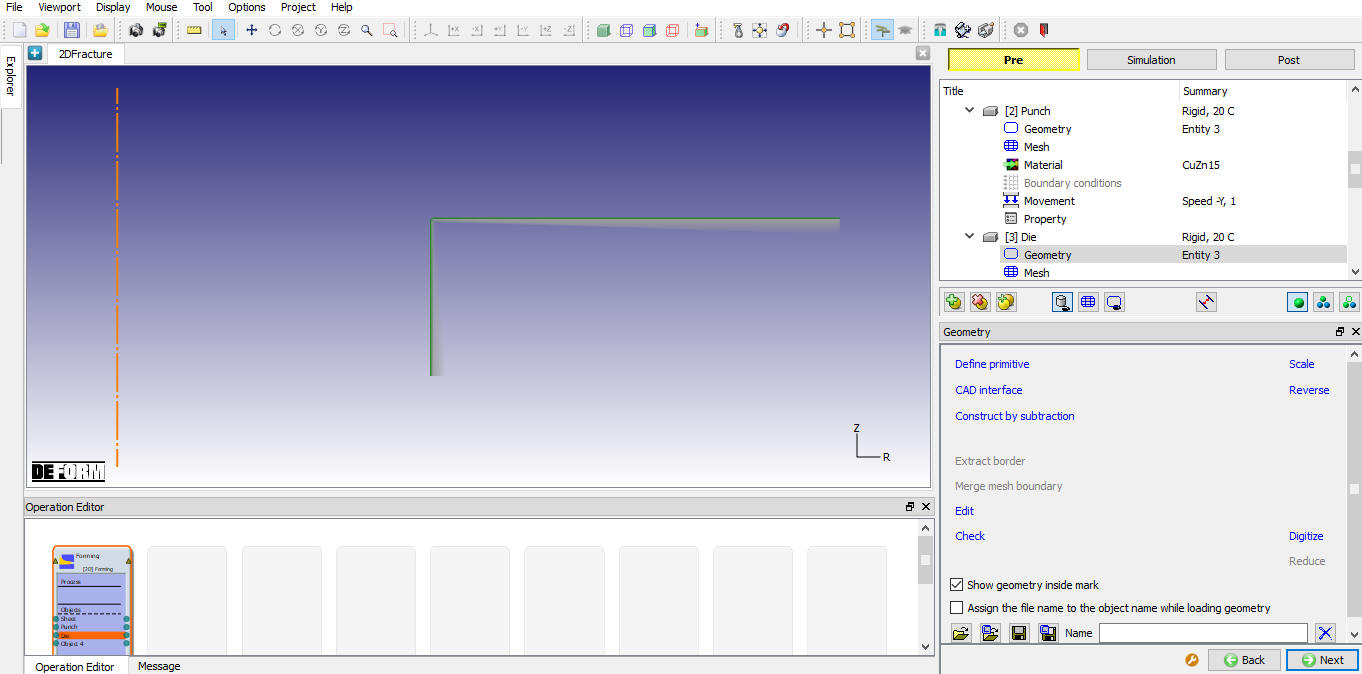
Importing the Die geometry
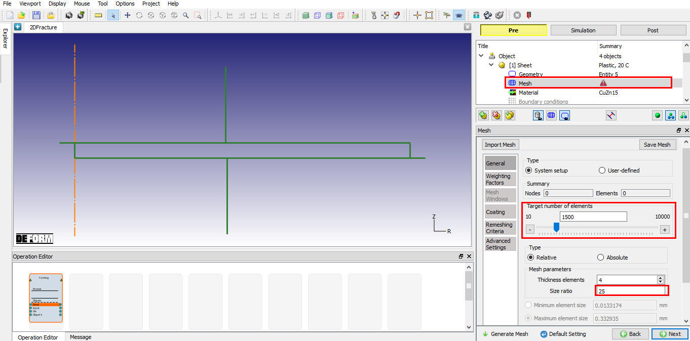
Generating mesh for Sheet
Select Mesh under Sheet object from operation tree to generate mesh as shown in Fig. 2DFRCL1.17. We will generate mesh with mesh windows as we require finer mesh near fracture region with good gradient.
To generate mesh with mesh windows we need to be in expert mode, click on ![]() icon to switch to expert mode. Define Targetnumber of elements as 1500 and size ratio as 25 as shown in Fig. 2DFRCL1.17.
icon to switch to expert mode. Define Targetnumber of elements as 1500 and size ratio as 25 as shown in Fig. 2DFRCL1.17.
Sheet object Mesh page
In Weighting Factors tab change the Mesh windows weighting factor value to 1 and other weighting factors to zero as shown in Fig. 2DFRCL1.18.
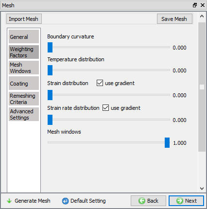
Defining the weighting factors for sheet object Mesh page
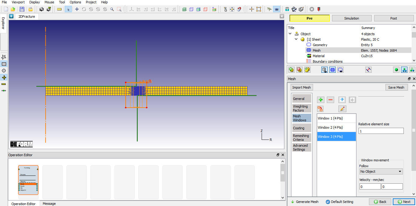
Now, select Mesh window tab and add three mesh windows. Define Window 1 closer to die inner surface with relative element size 0.015 as shown in Fig. 2DFRCL1.19. Define Window 2 such that it covers entire Window 1 as shown in Fig. 2DFRCL1.20. with relative element size0.125. Define Window 3 such that it covers entire Window 2 as shown in Fig. 2DFRCL1.21. with relative element size 1. Click the ![]() button to generate the mesh for Sheet as shown in the Fig. 2DFRCL1.22. Once mesh is generated, click
button to generate the mesh for Sheet as shown in the Fig. 2DFRCL1.22. Once mesh is generated, click ![]() until Object 4 object page or select Object 4 from operation tree.
until Object 4 object page or select Object 4 from operation tree.
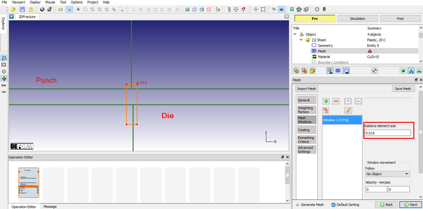
Defining Window 1 over Sheet object
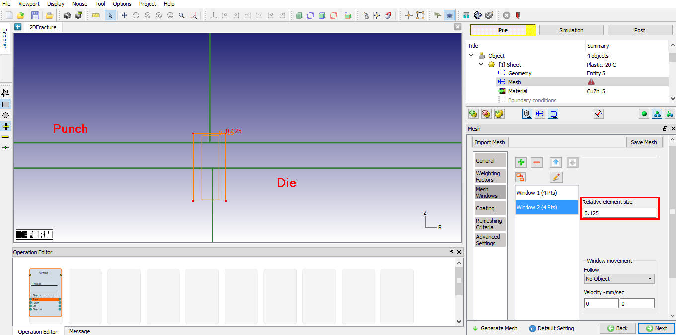
Defining Window 2 over Sheet object
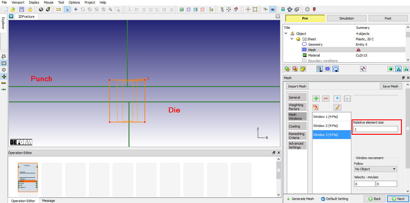
Defining Window 3 over Sheet object
Generated mesh for the sheet object
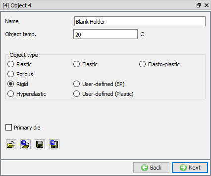
Defining Blank Holder object
Change the Object 4 name to Blank Holder. Use default temperature and select the object type as Rigid as shown in Fig. 2DFRCL1.23. Click ![]() button to define geometry.
button to define geometry.
Blank Holder object page
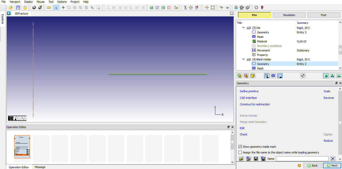
Importing the Blank Holder geometry
Click the ![]() (Load geometry from a file) button and import the file “ blankholder.geo ” from /2D/Labs/Fracture folder as shown in Fig. 2DFRCL1.24. Click
(Load geometry from a file) button and import the file “ blankholder.geo ” from /2D/Labs/Fracture folder as shown in Fig. 2DFRCL1.24. Click ![]() until Positioning page.
until Positioning page.
Importing the Blank Holder object
Positioning objects
Confirm that the Punch is positioned on the sheet and Die is positioned to Sheet. By default, the objects are positioned correctly so click ![]() to Contact page.
to Contact page.
Defining inter-object relations
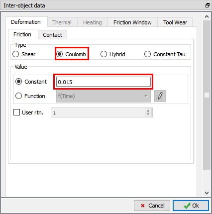
Select User type contact and click on ![]() button. It will add relationships between the Sheet, Punch, Die and Blank holder as shown in Fig. 2DFRCL1.26. Now select the Punch – Sheet relationship and click the
button. It will add relationships between the Sheet, Punch, Die and Blank holder as shown in Fig. 2DFRCL1.26. Now select the Punch – Sheet relationship and click the ![]() button to modify the friction values. In the Friction tab, under Deformation tab, define constant Coulomb friction of 0.015 as shown in Fig. 2DFRCL1.25.
button to modify the friction values. In the Friction tab, under Deformation tab, define constant Coulomb friction of 0.015 as shown in Fig. 2DFRCL1.25.
Inter-Object data definition window
Click ![]() to go back to contact window. Similarly define this friction condition for all the object pairs except Sheet - Sheet relation define shear friction as 0. Use
to go back to contact window. Similarly define this friction condition for all the object pairs except Sheet - Sheet relation define shear friction as 0. Use ![]() icon to determine a suitable contact tolerance then click on
icon to determine a suitable contact tolerance then click on ![]() button to generate contact (see Fig. 2DFRCL1.26.). Click on
button to generate contact (see Fig. 2DFRCL1.26.). Click on ![]() to define stopping controls.
to define stopping controls.
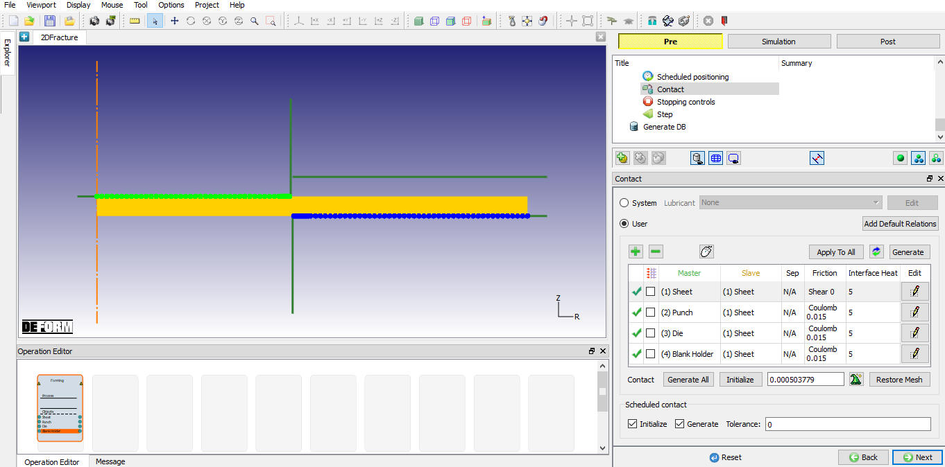
Contact geenrated between objects
Defining stopping Controls
In the Stopping Controls page, check the Primary die displacement option and then define the Y stroke value as 1.25 “ as shown in Fig. 2DFRCL1.27. Click on ![]() .
.
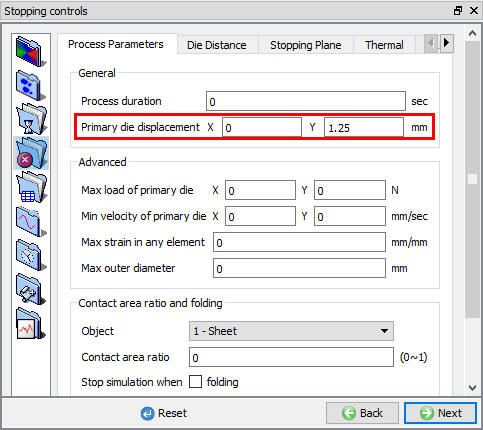
Defining stopping controls
Defining step controls
In step controls page, select ![]() and then define Number of Simulation steps as 500 , Step Increment to save as 25 and select Punch as Primary die. as shown in Fig. 2DFRCL1.28.
and then define Number of Simulation steps as 500 , Step Increment to save as 25 and select Punch as Primary die. as shown in Fig. 2DFRCL1.28.
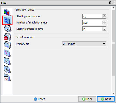
Defining step controls
Select ![]() and then select Die Displacement as Solution step definition type. Define 0.0025 mm/step in constant field. Define Max strain value 0.025 under Substepping controls as shown in Fig. 2DFRCL1.29. Make sure Contact time substepping is turned on.
and then select Die Displacement as Solution step definition type. Define 0.0025 mm/step in constant field. Define Max strain value 0.025 under Substepping controls as shown in Fig. 2DFRCL1.29. Make sure Contact time substepping is turned on.
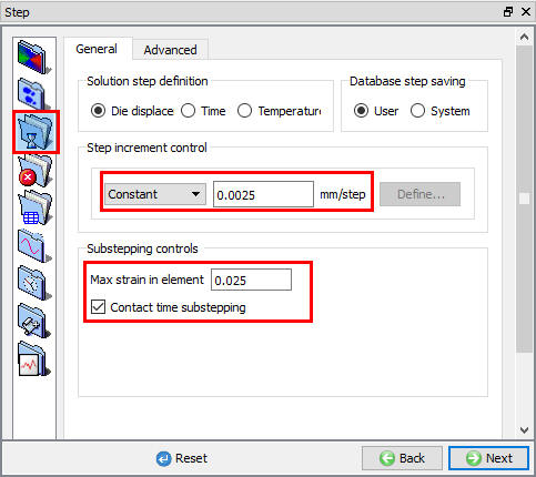
Defining step increment and Substepping controls
Select ![]() , In Deformation tab select “Newton-Raphson “ as Iteration method and “Skyline “ as the solver as shown in the Fig. 2DFRCL1.30.
, In Deformation tab select “Newton-Raphson “ as Iteration method and “Skyline “ as the solver as shown in the Fig. 2DFRCL1.30.
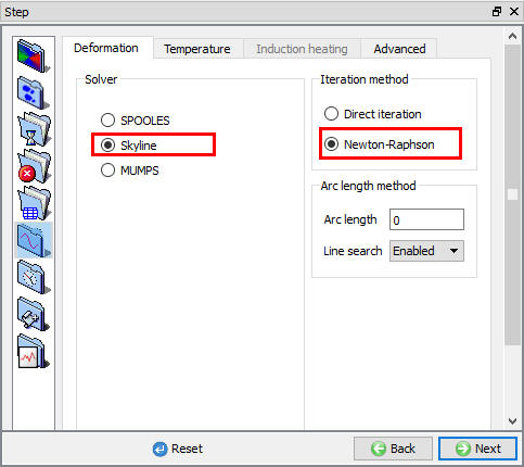
Setting Solver controls
Generating Database
In Generate DB page, click the ![]() button to have the program check to see if anything was missed in the problem setup. During the checking process, messages in the red color signify data that needs to be fixed before a simulation can be run (such as when you forget to define any material data).
button to have the program check to see if anything was missed in the problem setup. During the checking process, messages in the red color signify data that needs to be fixed before a simulation can be run (such as when you forget to define any material data).
Click on ![]() button to generate the database as shown in Fig. 2DFRCL1.31.
button to generate the database as shown in Fig. 2DFRCL1.31.
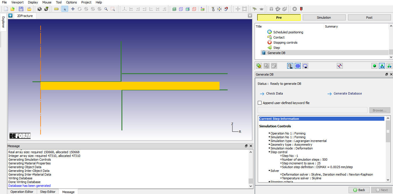
Generating Database
Running Simulation
Once the database has been generated, switch to the Simulation mode by clicking on ![]() button above the operation tree. Click on the
button above the operation tree. Click on the ![]() action label to open the Run Options dialog as shown in Fig. 2DFRCL1.32. Use the default Continue Run option to select “Continue from the last step ” (from step -1) option and then select the Simulation mode as Interactive and click on
action label to open the Run Options dialog as shown in Fig. 2DFRCL1.32. Use the default Continue Run option to select “Continue from the last step ” (from step -1) option and then select the Simulation mode as Interactive and click on ![]() button to run the simulation.
button to run the simulation.
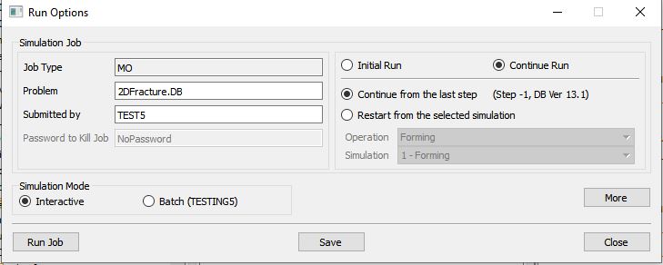
Run Simulation window
The progress of the simulation can be monitored as it is running by looking at the Simulation Message tab and Simulation Graphics from the Graphics display region in Simulation mode. If ![]() option is checked in Simulation Message tab, which is the default setting, the Message file will refresh automatically.
option is checked in Simulation Message tab, which is the default setting, the Message file will refresh automatically.
The Message file provides information about which simulation step the simulation is currently on and information dealing with how well the simulation is running as shown in Fig. 2DFRCL1.33.
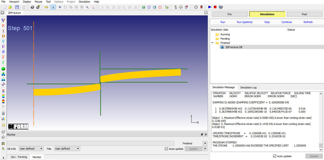
Simualtion mode
Post Processing
When the simulation is completed, review the results by switching to Post mode using the ![]() button above the Simulation tool bar.
button above the Simulation tool bar.
Go to last step of simulation and observe objects tab, we can observe new Sheet object (Object 5) is added which is fractured from original Sheet object (object 1). Now uncheck the Die, Punch and Blank Holder check box from visible icon column in objects tab, see Fig. 2DFRCL1.34.
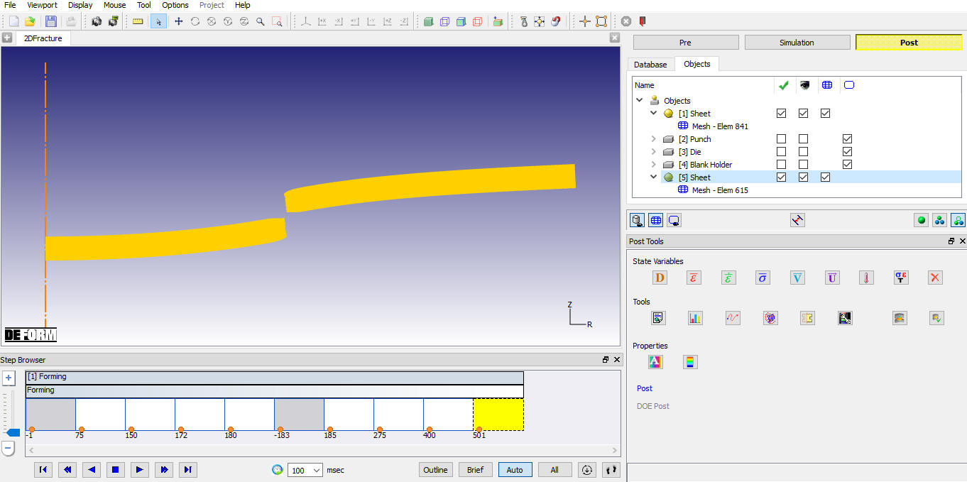
Sheet object fractured into two objects
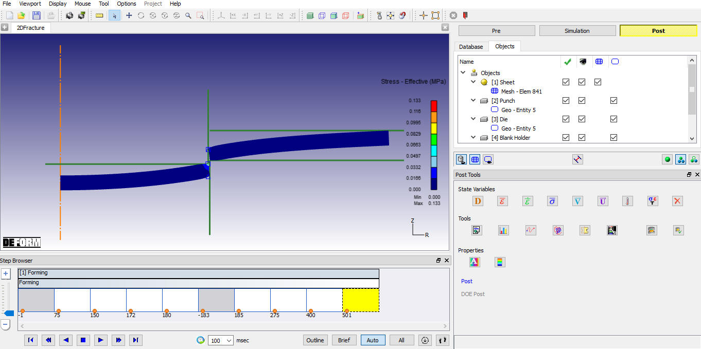
Stress state variable plot
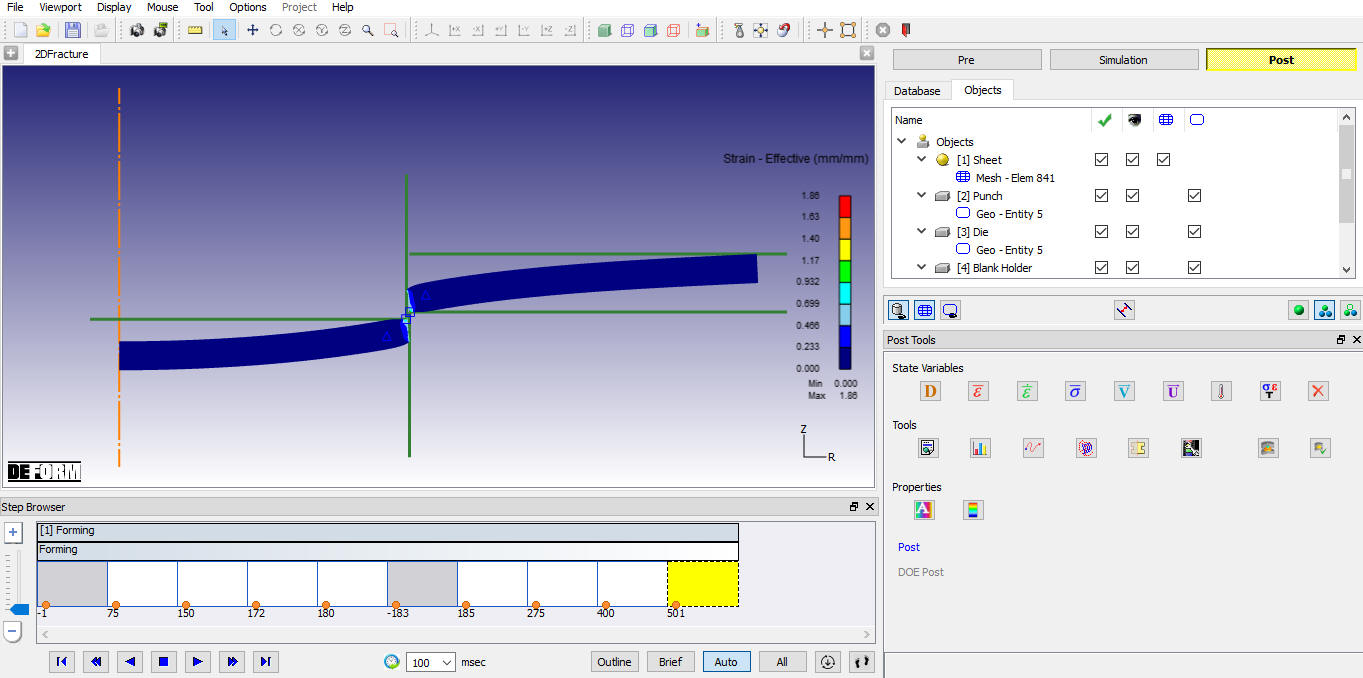
Strain state variable plot