Ring Rolling Lab3
In this lab we will be setting up simple Isothermal Ring Rolling operation.
3.1. Creating a New Problem
3.2. Process Page
3.3. Simulation Setup
3.4.Object selection
3.5. Defining Workpiece - Ring
3.5.1. Defining Workpiece - Ring object
3.5.2. Defining Workpiece - Ring 2D cross-section
3.5.3. Defining Workpiece - Ring 2D Mesh
3.5.4. Generating 3D Geometry for Workpiece - Ring
3.5.5. Generating 3D Mesh for Workpiece - Ring
3.5.6. Assign Workpiece-Ring Material
3.6. Defining Driving Roll
3.6.1. Defining Driving Roll Object
3.6.2. Driving roll 2D cross-section Page
3.6.3. Driving Roll 3D Geometry Page
3.6.4. Driving Roll orientation
3.6.5. Driving roll movement
3.7. Defining Pressure Roll
3.7.1. Defining Pressure Roll Object
3.7.2. Pressure roll 2D cross-section Page
3.7.3. Pressure Roll 3D Geometry Page
3.7.4. Pressure Roll orientation
3.7.5. Pressure roll movement
3.8. Contact Page
3.9. Stopping Controls
3.10. Step and Remeshing controls Page
3.11. Generate Database
3.12. Running Simulation
3.13. Post Processing
Creating a New Problem
On a Windows machine , go to the ![]() button select DEFORM-v1x.xxx (.xxx indicates version number E.g. v14.0.2) and select DEFORM GUI Main vxx.xx from the menu. The DEFORM GUI Main window will appear.
button select DEFORM-v1x.xxx (.xxx indicates version number E.g. v14.0.2) and select DEFORM GUI Main vxx.xx from the menu. The DEFORM GUI Main window will appear.
Create a new problem either by selecting File![]() **New Problem** or by clicking the New Problem
**New Problem** or by clicking the New Problem ![]() icon. The Problem Setup window will appear as shown in Fig. RRL3.1. Select “ Integrated Manufacturing Process “ radio button and Unit system as “English “ using radio button. Define Problem Name as “RING_ROLL_LAB3 “ and make sure the “Show option dialog” check box is turned on (if we do not turn on the “Show option dialog ” check box, then we will not get the New Project dialog in MO UI). Then click on
icon. The Problem Setup window will appear as shown in Fig. RRL3.1. Select “ Integrated Manufacturing Process “ radio button and Unit system as “English “ using radio button. Define Problem Name as “RING_ROLL_LAB3 “ and make sure the “Show option dialog” check box is turned on (if we do not turn on the “Show option dialog ” check box, then we will not get the New Project dialog in MO UI). Then click on ![]() button to open a new Problem using the Deform Integrated Manufacturing Process.
button to open a new Problem using the Deform Integrated Manufacturing Process.
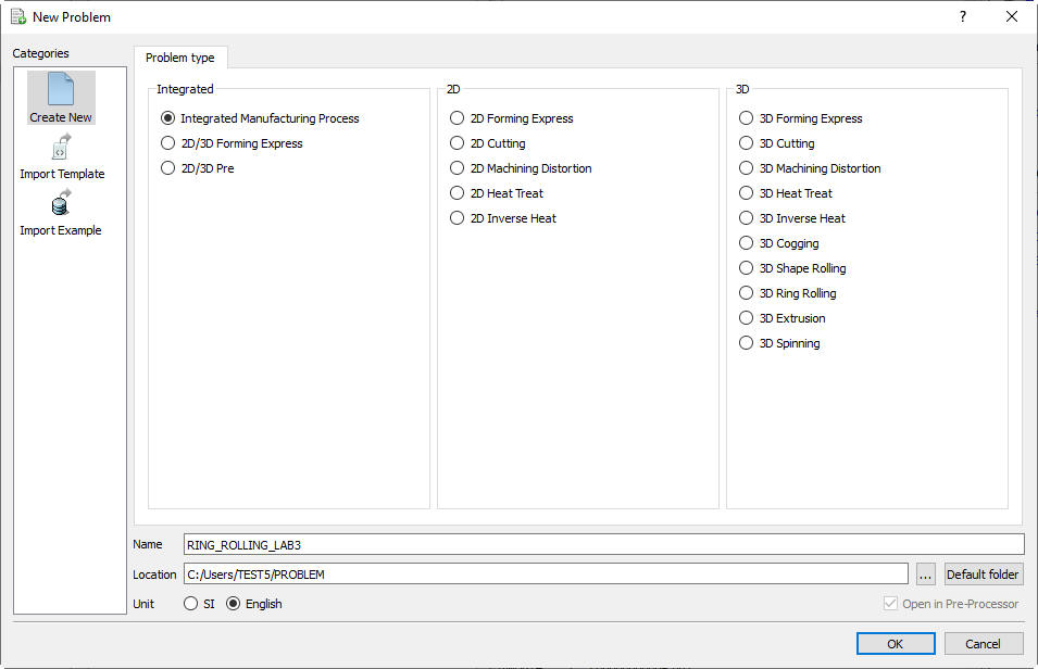
New Problem page
Multiple operation wizard will open with the New Project dialog, at this point user will be prompted to specify a project name (system will create a separate folder with this project name) and title for this session. In this session, we will use ‘RING_ROLLING_LAB3 ’ as the project name. 3D Ring Rolling operation can be added in “New Project” dialog buy turning on First operation check band selecting Ring Rolling operation from the drop down menu (see Fig. RRL3.2.) In this lab, we will add Ring rolling operation from Explorer operation list, so do not check “First operation” check box in “New Project” dialog. Click on ![]() to continue to add the operation.
to continue to add the operation.
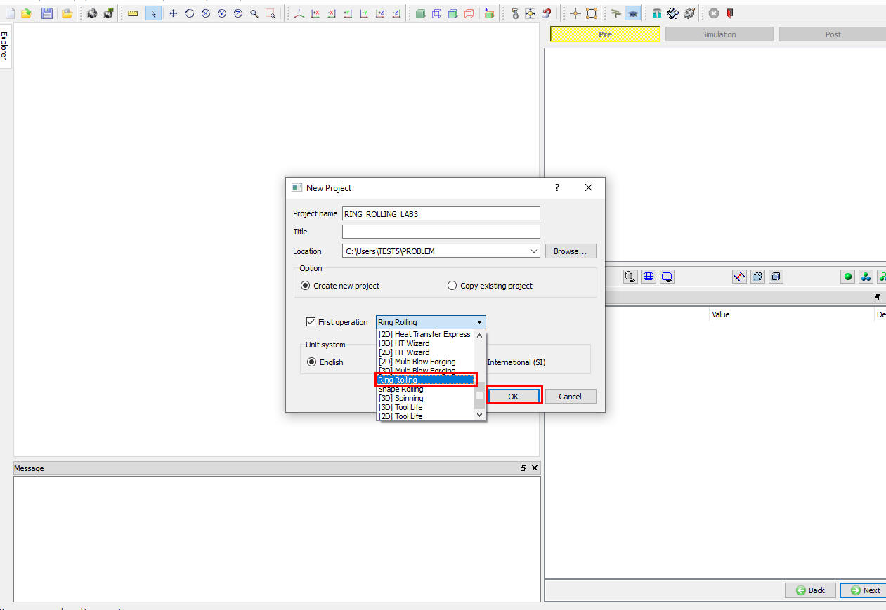
Adding Ring rolling operation from New Project
Add 3D Ring Rolling operation from the Explorer Operations list. Add the operation by clicking on ![]() button available next to 3D Ring Rolling or user can also add by drag and drop into the Operation Editor. When we add the Ring Rolling operation, Process settings page will be opened by default (See Fig. RRL3.3.).
button available next to 3D Ring Rolling or user can also add by drag and drop into the Operation Editor. When we add the Ring Rolling operation, Process settings page will be opened by default (See Fig. RRL3.3.).
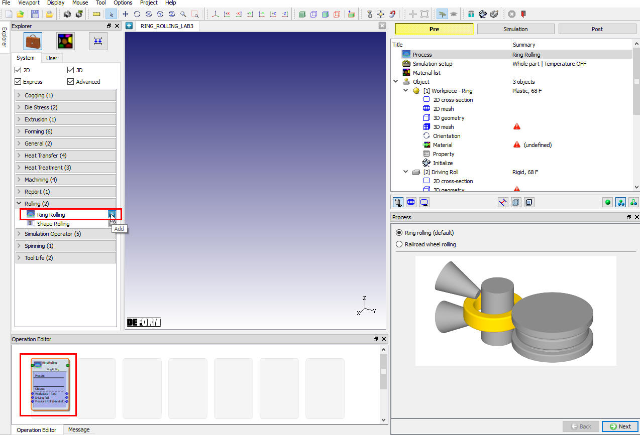
Adding Ring rolling operation from Explorer
Process Page
Ring rolling operation template can be used to setup Ring Rolling and Railroad wheel rolling, In Process page, by default “Ring rolling (default) “ radio button will be selected (See Fig. RRL3.4.), we will retail this selection and click on ![]() to Simulation setup page.
to Simulation setup page.
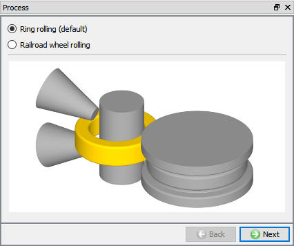
Process page
Simulation Setup
Select “Whole “ 3D model type radio button and keep default Thermal calculation type as “C**o nstant temperature (isothermal)**” in Simulation setup page as shown in Fig. RRL3.5. Click on ![]() until Objects page.
until Objects page.
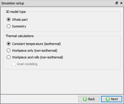
Simulation setup page
Object selection
In “Objects ” page, we will use the current default objects as shown in Fig. RRL3.6., minimum 3 objects are required to setup ring rolling process, they are Workpiece (Ring), Pressure roll (mandrel) and Driving roll. We will not using any axial roll in this lab. Click on ![]() to Workpiece - Ring page to define Ring object.
to Workpiece - Ring page to define Ring object.
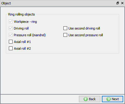
Objects list for Whole model type
Defining Workpiece - Ring
Defining Workpiece - Ring object
In Workpiece - Ring page define the Object temperature as 70 °F as shown in Fig. RRL3.7., click on ![]() to 2D Cross-section page.
to 2D Cross-section page.
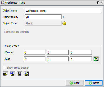
Workpiece - Ring Object page
Defining Workpiece - Ring 2D cross-section
In Workpiece 2D cross-section page, click on ![]() and selectH**ollo w** cylinder primitive, define the Outer radius as “8 ”, Inner radius as “6 “, Height as “2 ” and Cornersradius as**0.25** at all corners as shown in Fig. RRL3.8. Click on
and selectH**ollo w** cylinder primitive, define the Outer radius as “8 ”, Inner radius as “6 “, Height as “2 ” and Cornersradius as**0.25** at all corners as shown in Fig. RRL3.8. Click on ![]() to close the Geometry primitive page and click on
to close the Geometry primitive page and click on ![]() to 2D Mesh page.
to 2D Mesh page.
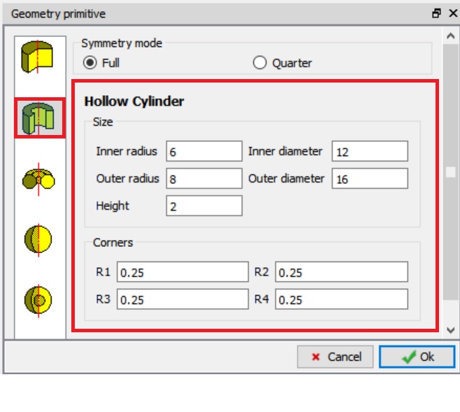
Workpiece – Ring 2D cross-section geometry definition
Defining Workpiece - Ring 2D Mesh
In 2D mesh settings, define Target number of Elements as 100 , click on ![]() button and observe the generated mesh in display window (See Fig. RRL3.9.). Click on
button and observe the generated mesh in display window (See Fig. RRL3.9.). Click on ![]() to 3D Geometry page.
to 3D Geometry page.
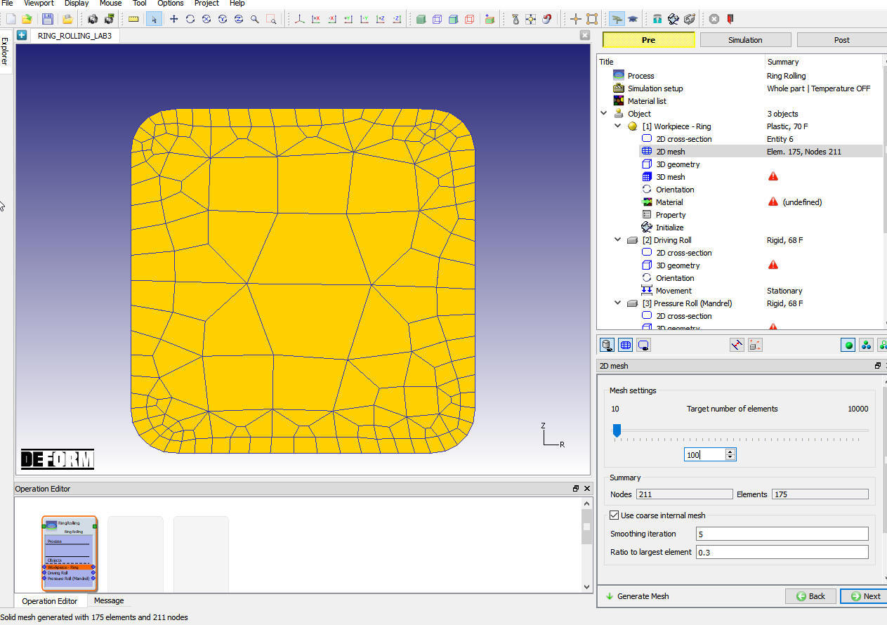
Workpiece-Ring 2D Mesh generation
Generating 3D Geometry for Workpiece - Ring
In 3D Geometry page, click on “Revolve from 2D “ option, use the default values in Revolve from 2D page as shown in Fig. RRL3.10., and click ![]() to close. Click on
to close. Click on ![]() to 3D Mesh page.
to 3D Mesh page.
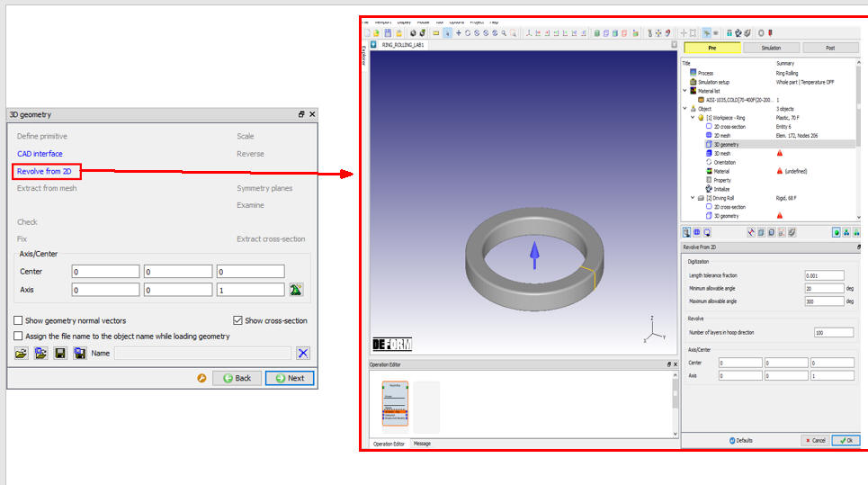
Workpiece-Ring 3D Geometry settings
Generating 3D Mesh for Workpiece - Ring
In 3D Mesh page, select Revolve with constant cross-section radio button and with default value of 120 for “Number of Revolving sections “, generate 3D mesh by clicking on ![]() . Observe the generated 3D Mesh for workpiece as shown in Fig. RRL3.11. If Ring is of non-uniform shape then user can import the geometry and select Revolve to fit 3D shape to generate non-uniform 3D Ring Mesh. Click on
. Observe the generated 3D Mesh for workpiece as shown in Fig. RRL3.11. If Ring is of non-uniform shape then user can import the geometry and select Revolve to fit 3D shape to generate non-uniform 3D Ring Mesh. Click on ![]() until Material page.
until Material page.
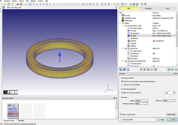
Workpiece-Ring 3D Mesh settings
Assign Workpiece-Ring Material
In Material page, Click on ![]() (Load material from library) icon and load the steel group material “AISI-1035,COLD[70-400F(20-200C)] “ from material library window. Assign the “AISI-1035,COLD[70-400F(20-200C)] “ material for Workpiece as shown in Fig. RRL3.12. Click on
(Load material from library) icon and load the steel group material “AISI-1035,COLD[70-400F(20-200C)] “ from material library window. Assign the “AISI-1035,COLD[70-400F(20-200C)] “ material for Workpiece as shown in Fig. RRL3.12. Click on ![]() to Workpiece BCC page.
to Workpiece BCC page.
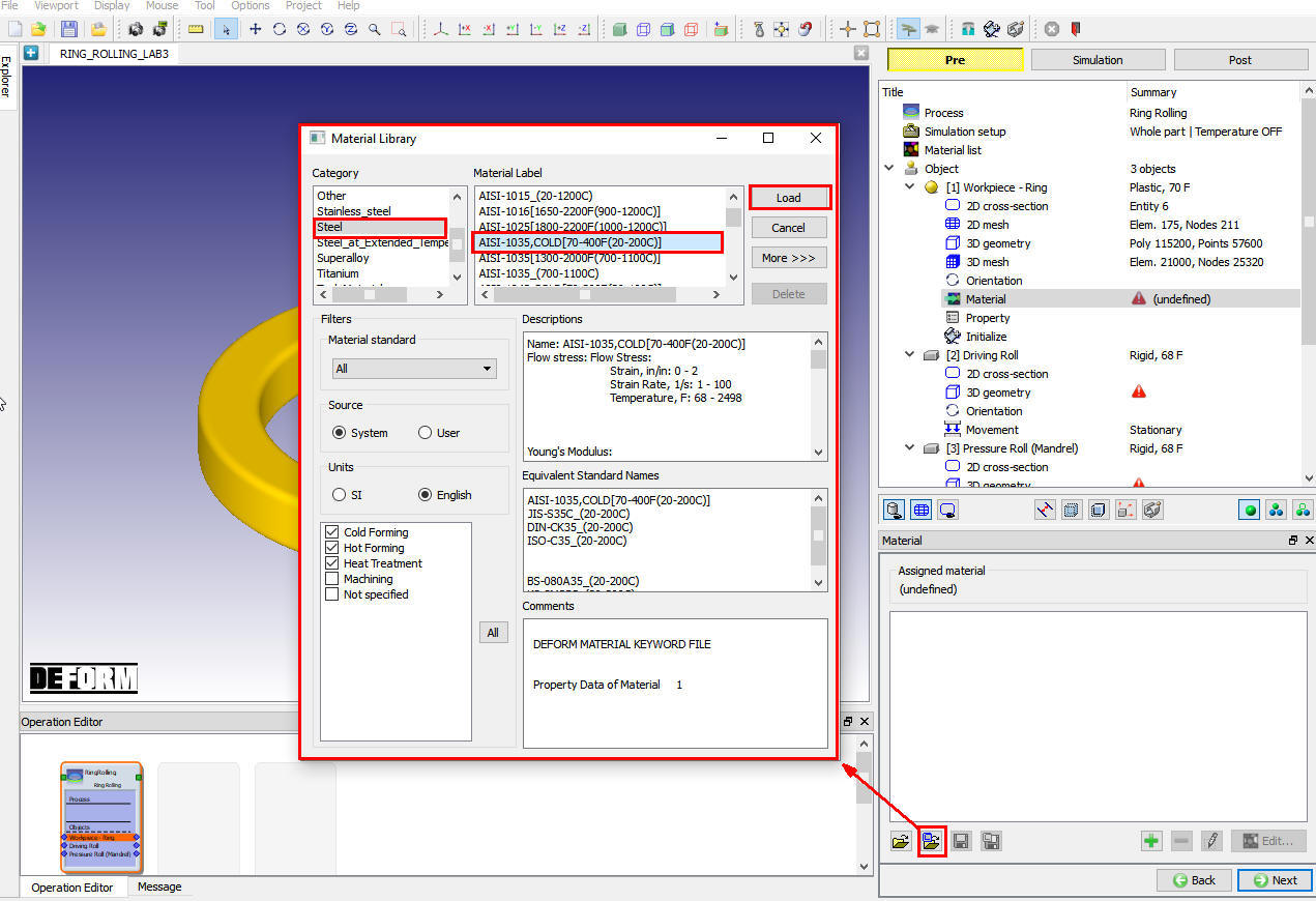
Workpiece-Ring material Page
Defining Driving Roll
Defining Driving Roll Object
Keep the name as “Driving Roll “ and temperature as68°F unchanged as shown in Fig. RRL3.13. and just click ![]() to go to the 2D cross-section geometry page.
to go to the 2D cross-section geometry page.
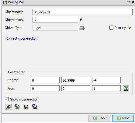
Driving Roll object Page
Driving roll 2D cross-section Page
In Driving Roll 2D cross-section page, click on ![]() and select H**o llow cylinder primitive, define the **Outer radius as “19 “, Inner radius as “14 “and height as “10 ” as shown in Fig. RRL3.14. Click on
and select H**o llow cylinder primitive, define the **Outer radius as “19 “, Inner radius as “14 “and height as “10 ” as shown in Fig. RRL3.14. Click on ![]() to close the Geometry primitive page and click on
to close the Geometry primitive page and click on ![]() to 3D Geometry page.
to 3D Geometry page.
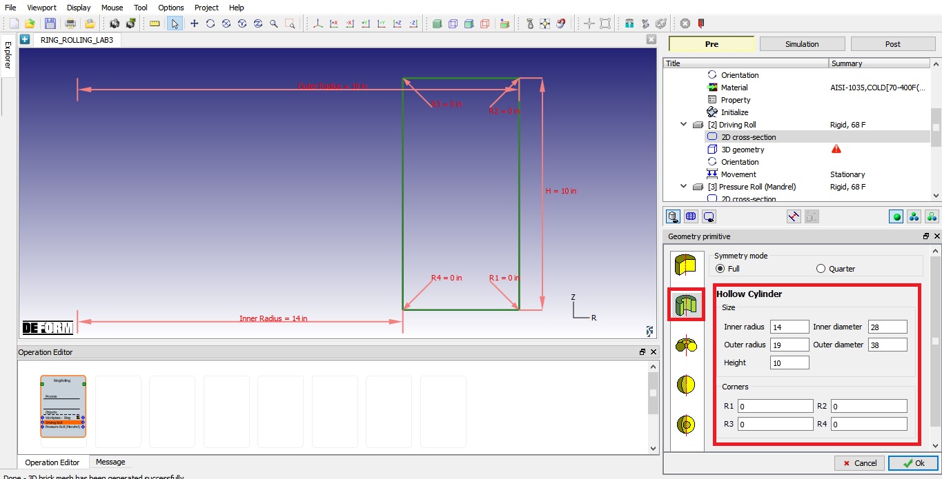
Defining Driving roll 2D cross section
Driving Roll 3D Geometry Page
In 3D Geometry page, click on “Revolve from 2D “ option as shown in Fig. RRL3.15., use the default value of 100 as “Number of layers in hoop direction “ in Revolve from 2D page as shown in Fig. RRL3.15.. and click ![]() to generate 3D geometry as shown in Fig. RRL3.15.. and close. Click on
to generate 3D geometry as shown in Fig. RRL3.15.. and close. Click on ![]() to Orientation page.
to Orientation page.
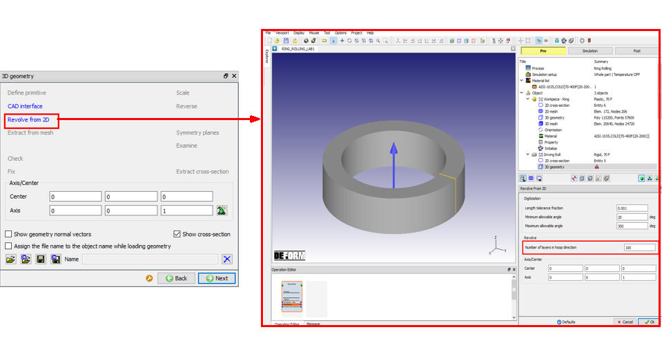
Driving roll 3D Geometry settings
Driving Roll orientation
In Driving Roll orientation page, select “Set relative distance between object center “ option and define “ Vertical distance (d) “ as 4 in with “Current object center’s relative location “ as “-Z “, click on ![]() to move the Driving Roll by 2.25 in along the Z axis with respect to Ring object center (See Fig. RRL3.16.). Click on
to move the Driving Roll by 2.25 in along the Z axis with respect to Ring object center (See Fig. RRL3.16.). Click on ![]() to Movement page.
to Movement page.
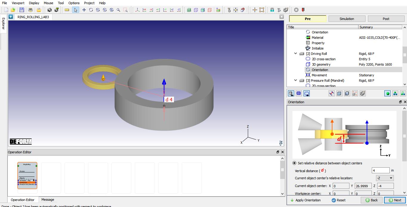
Defining Driving Roll Orientation
Driving roll movement
Select Angular velocity in rotation movement controls for the driving roll and define a constant value2 rad/sec. Notice a green rotation arrow showing rotational direction in the display window (See Fig. RRL3.17.). Click on ![]() to Object page of Pressure roll.
to Object page of Pressure roll.
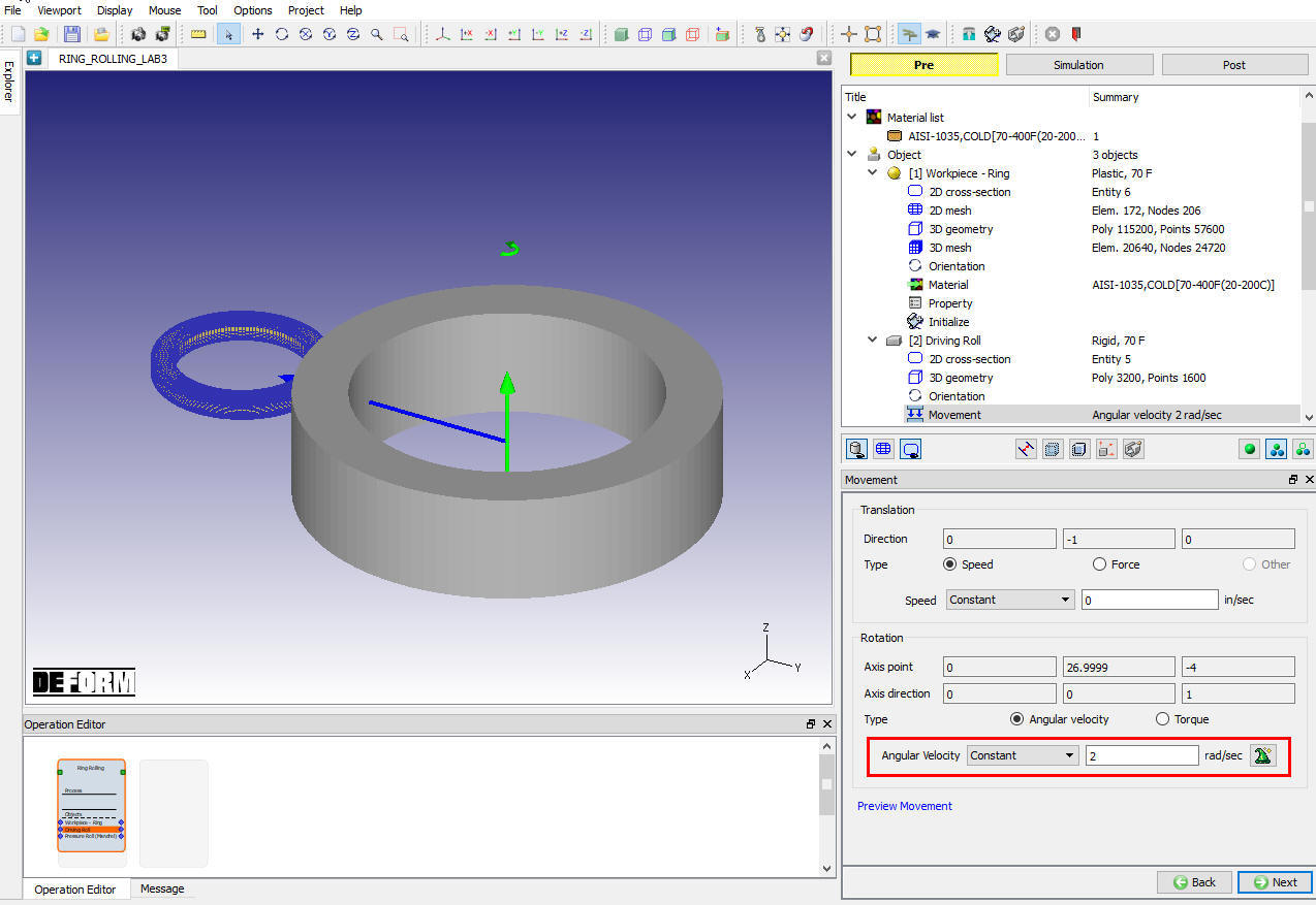
Driving Roll Movement definition
Defining Pressure Roll
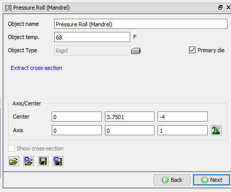
Defining Pressure Roll Object
Keep the name of “PressureRoll “ and temperature as 68°F as shown in Fig. RRL3.18. and click ![]() to go to the 2D cross-section page.
to go to the 2D cross-section page.
Pressure Roll object page
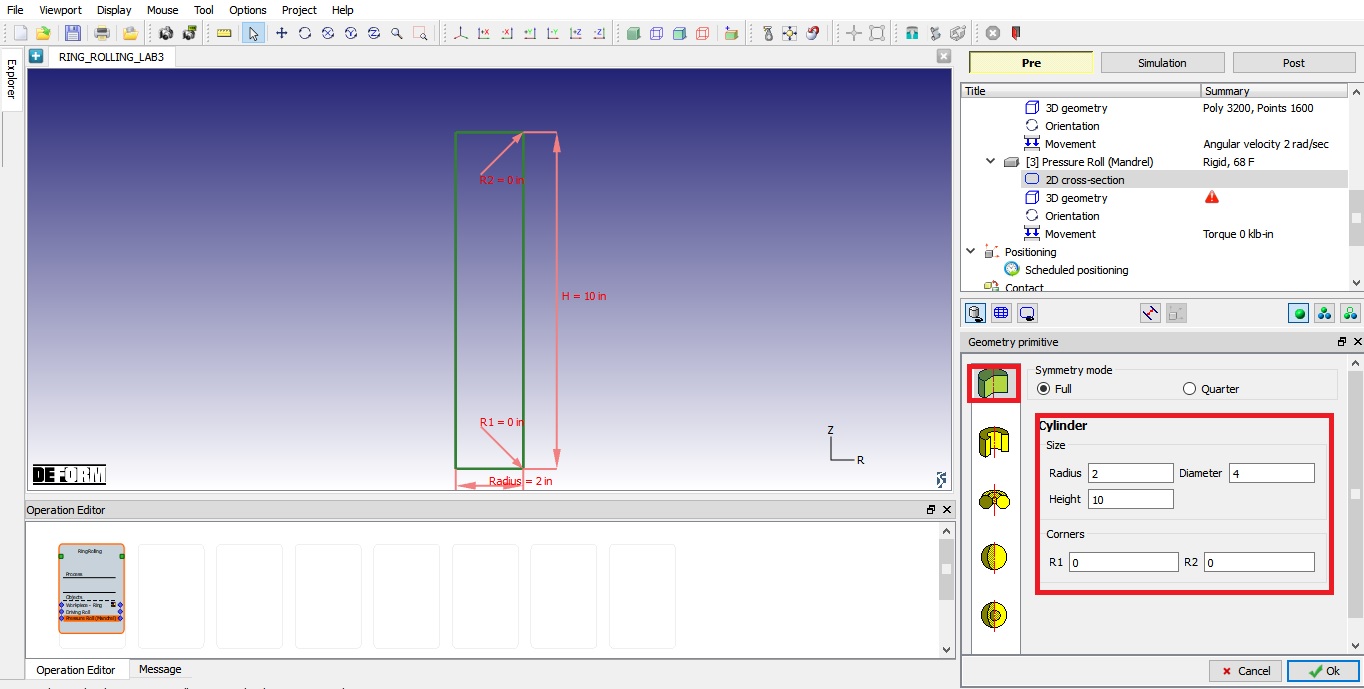
Pressure roll 2D cross-section Page
In Pressure roll 2D cross-section page, click on ![]() and select cylinder primitive define the R**a dius and **Height as 2 ” and 10 ” respectively as shown in Fig. RRL3.19. Click on
and select cylinder primitive define the R**a dius and **Height as 2 ” and 10 ” respectively as shown in Fig. RRL3.19. Click on ![]() to close the Geometry primitive page and click on
to close the Geometry primitive page and click on ![]() to 3D Geometry page.
to 3D Geometry page.
Defining Pressure Roll 2D Cross-section Geometry
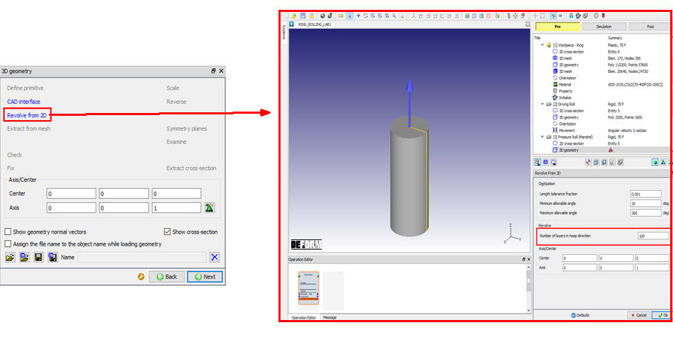
Pressure Roll 3D Geometry Page
In 3D Geometry page, click on “Revolve from 2D “ option as shown in Fig. RRL3.20., use the default value of 100 for “Number of layers in hoop direction “ in Revolve from 2D page in as shown in Fig. RRL3.20. and click ![]() to generate 3D geometry for Pressure Roll as shown in Fig. RRL3.20. and close. Click on
to generate 3D geometry for Pressure Roll as shown in Fig. RRL3.20. and close. Click on ![]() to Orientation page.
to Orientation page.
Pressure Roll 3D geometry settings
Pressure Roll orientation
Select “Set relative distance between object centers “ option and define “ Vertical distance (d) “ as 4.5 in with “Current object center’s relative location “ as “-Z “, click on ![]() to move the Pressure Roll down along Z axis by 4.5 in (See Fig. RRL3.21.) in Pressure Roll Orientation page. Click on
to move the Pressure Roll down along Z axis by 4.5 in (See Fig. RRL3.21.) in Pressure Roll Orientation page. Click on ![]() to Movement page.
to Movement page.
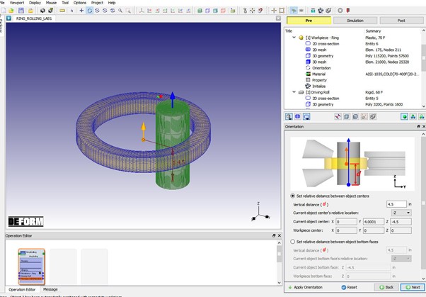
Pressure Roll Orientation settings
Pressure roll movement
We will define Pressure Roll movement Speed as “Constant “ as “0.01 in/sec” while keeping Torque at “0 ” as shown in Fig. RRL3.22. Click on ![]() until Contact page.
until Contact page.
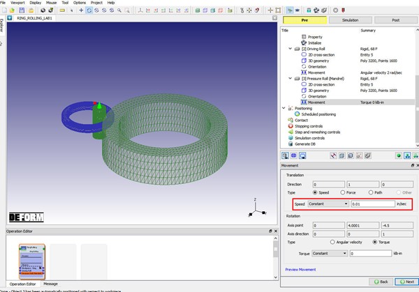
Pressure Roll movement page
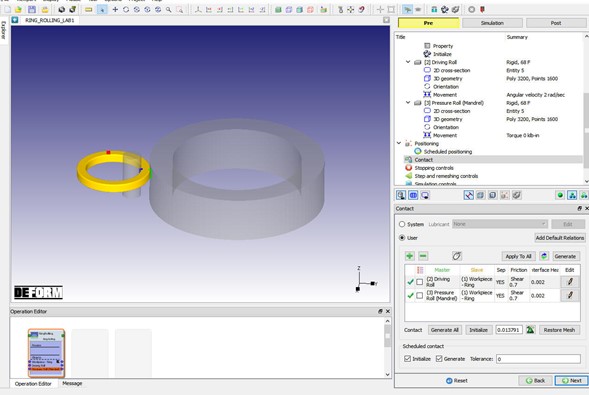
Contact Page
In Contact page, we will use the default shear friction value of 0.7 as shown in Fig. RRL3.23. and click on ![]() to generate contacts between driving roll and the workpiece as well as between pressure roll and the workpiece (See Fig. RRL3.23.). Click on
to generate contacts between driving roll and the workpiece as well as between pressure roll and the workpiece (See Fig. RRL3.23.). Click on ![]() to Stopping controls page.
to Stopping controls page.
Contact page
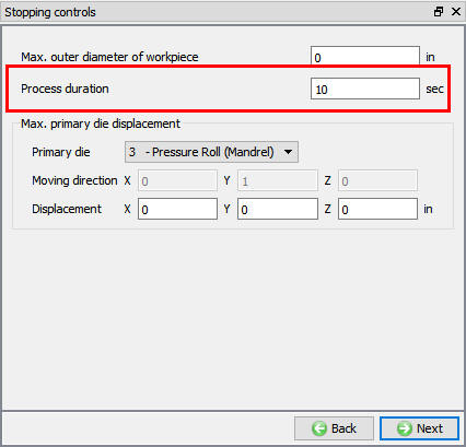
Stopping Controls
Define processduration as 10 sec as shown in Fig. RRL3.24. Click on ![]() to Step and remeshing control page.
to Step and remeshing control page.
Stopping control page
Step and Remeshing controls Page
Keep default Numberof steps of 10000 , set Rotationincrementto save as 90 and Maxallowedtimestep as 0.01. Keep default “Remeshing control ” as “5 revolutions(s)” as shown in Fig. RRL3.25. Click on ![]() until Generate DB.
until Generate DB.
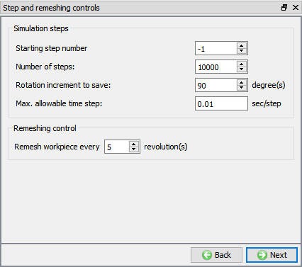
Step and remeshing control page
Generate Database
In Generate DB page, click on the ![]() button to generate the database. Observe the message in Message tab informing database generation status.
button to generate the database. Observe the message in Message tab informing database generation status.
Running Simulation
Once the database has been generated, switch to the Simulation mode by selecting the ![]() button above the object tree. Click on the
button above the object tree. Click on the ![]() action label to open the Run Options dialog as shown in Fig. RRL3.26. Use the default Continue Run option to select “Continue from the last step ” (from step -1) option and then select the Simulation mode as Interactive and click on
action label to open the Run Options dialog as shown in Fig. RRL3.26. Use the default Continue Run option to select “Continue from the last step ” (from step -1) option and then select the Simulation mode as Interactive and click on ![]() button to run the simulation.
button to run the simulation.
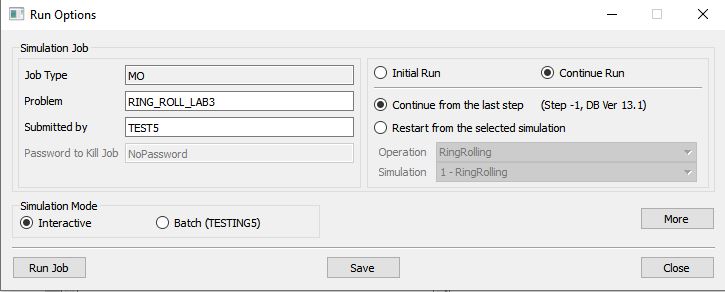
Run Simulation Window
Monitor the progress of the simulation by looking at the Simulation Message and Simulation Log tab, making sure that the ![]() option is checked. User can view the Ring Rolling process as the simulation proceeds to the specified stopping criteria from Simulation graphics.
option is checked. User can view the Ring Rolling process as the simulation proceeds to the specified stopping criteria from Simulation graphics.
Post Processing
When the simulation is completed with ‘normal stop’, review the results by switching to Post mode using the ![]() button above the Simulation tool bar.
button above the Simulation tool bar.
Play through the steps of the simulation and look how the workpiece-Ring is formed.
Click on ![]() Single object mode by selecting workpiece-Ring and plot Effective Stress of the workpiece-Ring. When we play through the steps, we can observe the increase in strain value. The Effective Stress distribution at the step 163 of the simulation should look like as shown in Fig. RRL3.27. The dimension of the ring at the last step is as shown in Fig. RRL3.28.
Single object mode by selecting workpiece-Ring and plot Effective Stress of the workpiece-Ring. When we play through the steps, we can observe the increase in strain value. The Effective Stress distribution at the step 163 of the simulation should look like as shown in Fig. RRL3.27. The dimension of the ring at the last step is as shown in Fig. RRL3.28.
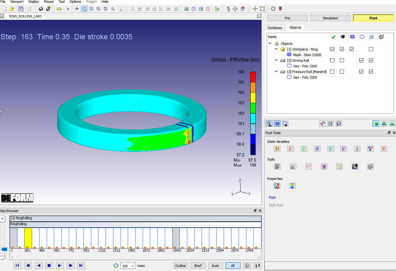
Showing effective stress
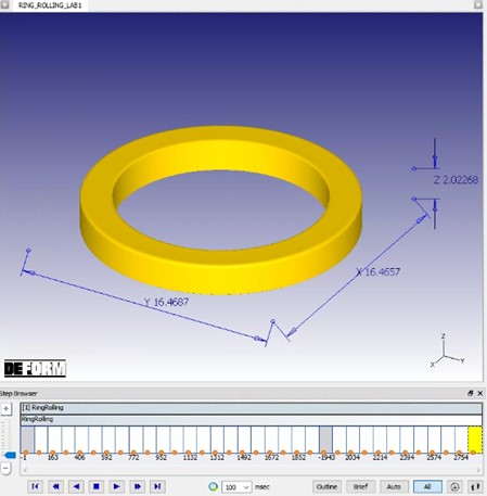
Dimensions of Ring at end of simulation