Shape Rolling Lab2 (Lagrangian using Brick mesh)
In this lab we will be setting up simple Lagrangian multi-pass rolling operation using Shape Rolling template available in Integrated Manufacturing Process template.
2.1. Creating a New problem
2.2. Adding Shape Rolling operation
2.3. Set process conditions
2.4. Defining Workpiece
2.4.1. Defining Workpiece object
2.4.2. Creating Workpiece Geometry
2.4.3. Generating Workpiece mesh
2.4.4. Assigning Workpiece material
2.4.5. Defining Workpiece boundary conditions
2.5. Defining Grooves
2.5.1. Defining Grooves for Roll geometry
2.6. Defining 4 passes with 2 Stands in 3rd and 4th pass
2.7. Generating 3D Setup
2.7.1. 3D Roll geometry settings
2.7.2. 3D Roll mesh settings
2.7.3. 3D Workpiece setup using Brick mesh
2.7.4. Pusher definition
2.8. Simulation controls in rolling group level
2.9. Modifying Rolling pass operation 1 (Pass 1)
2.9.1. Stand table for pass 1
2.9.2. Table back
2.9.2.1. Defining Table back geometry
2.9.2.2. Table back Mesh Generation
2.9.2.3. Table Back Material assigning
2.9.3. Pusher object
2.9.3.1. Pusher object movement definition
2.9.4. Object positioning
2.9.5. Defining Contact Relations
2.9.6. Defining Simulation Controls
2.9.7. Generating Database
2.10. Modifying Rolling pass operation 2 (Pass 2)
2.10.1. Creating the table geometry and generating the mesh
2.10.2. Pusher object movement definition
2.10.3. Schedule positioning definition
2.10.4. Simulation controls page
2.11. Modifying Rolling pass operation 3 (Pass 3)
2.11.1. Creating the table geometry and generating the mesh
2.11.2. Defining movement for stand2 rolls
2.11.3. Pusher object movement definition
2.11.4. Schedule positioning definition
2.11.5. Simulation controls page
2.12. Modifying Rolling pass operation 4 (Pass 4)
2.12.1. Creating the table geometry and generating the mesh
2.12.2. Defining movement for stand2 rolls
2.12.3. Pusher object movement definition
2.12.4. Schedule positioning definition
2.12.5. Simulation controls page
2.13. Running simulation
2.14. Post Processing
Creating a New problem
On a Windows machine , go to the ![]() button select DEFORM-v1x.xxx (.xxx indicates version number E.g. v14.0.2) and select DEFORM GUI Main vxx.xx from the menu. The DEFORM GUI Main window will appear.
button select DEFORM-v1x.xxx (.xxx indicates version number E.g. v14.0.2) and select DEFORM GUI Main vxx.xx from the menu. The DEFORM GUI Main window will appear.
Create a new problem either by selecting File![]() **New Problem** or by clicking the New Problem
**New Problem** or by clicking the New Problem ![]() icon. The Problem Setup window will appear as shown in Fig. L2.1. Select “Integrated Manufacturing Process “ radio button and unit system as “SI “ using radio button. Define Problem Name as “SHR_LAG_LAB2 “ and make sure the “Show option dialog ” check box is turned on (if we do not turn on the “Show option dialog ” check box, then we will not get the New Project dialog in MO UI). Then click on
icon. The Problem Setup window will appear as shown in Fig. L2.1. Select “Integrated Manufacturing Process “ radio button and unit system as “SI “ using radio button. Define Problem Name as “SHR_LAG_LAB2 “ and make sure the “Show option dialog ” check box is turned on (if we do not turn on the “Show option dialog ” check box, then we will not get the New Project dialog in MO UI). Then click on ![]() button to open a new Problem using the Deform Integrated Manufacturing Process.
button to open a new Problem using the Deform Integrated Manufacturing Process.
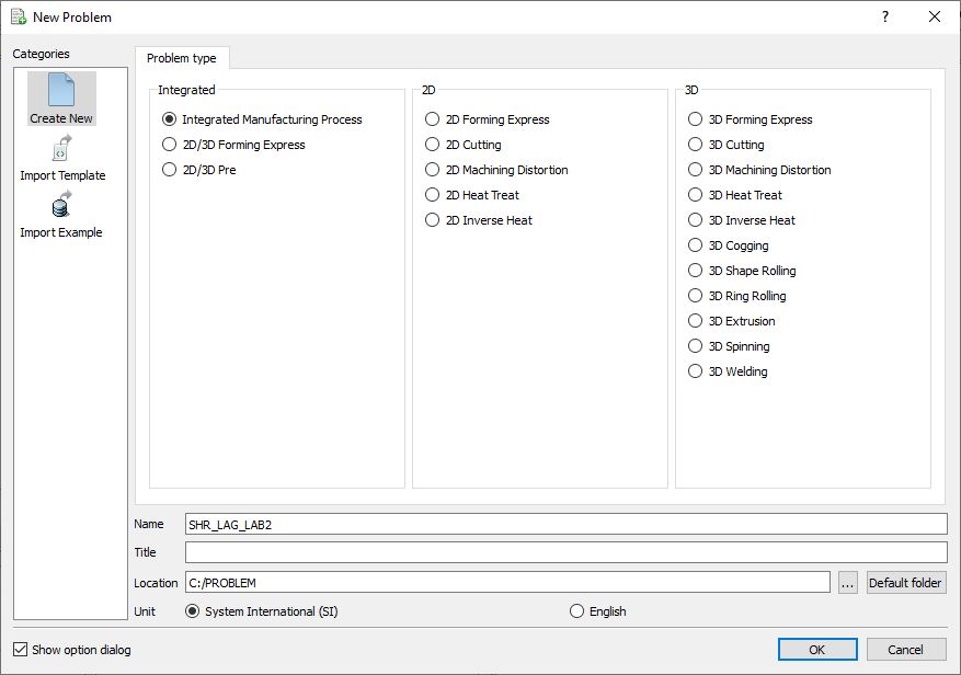
Problem type selection window
Multiple operation wizard will open with the New Project dialog as shown in Fig. L2.2., at this point user will be prompted to specify a project name (system will create a separate folder with this project name) and title for this session. In this session we will use ‘**SHR_LAG_LAB2** ’ as the project name. 3D Shape Rolling operation can also be added in “New Project” dialog (see Fig. L2.2.), in this lab we will add Shape rolling operation from Explorer operation list, so do not check “First operation” check box and “Shape Rolling” operation in “New Project” dialog. Click on ![]() to continue to open the operation.
to continue to open the operation.
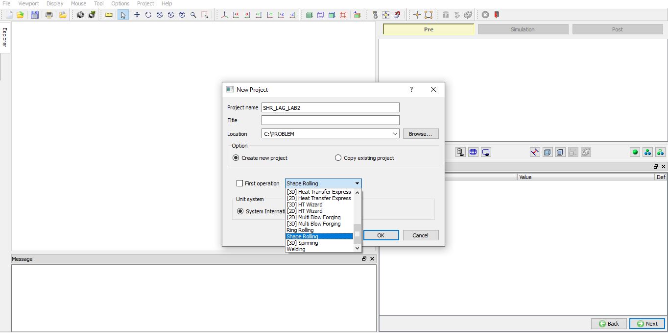
Adding Shape Rolling Operation in MO UI from new Project window.
Adding Shape Rolling operation
Add one Shape Rolling operation from the Explorer Operations list. Operation can be added by clicking on Shape Rolling operation ![]() button or user can also add by drag and drop into the Operation Editor. (See Fig. L2.3.). As we add operation, Process page will be opened in the properties area.
button or user can also add by drag and drop into the Operation Editor. (See Fig. L2.3.). As we add operation, Process page will be opened in the properties area.
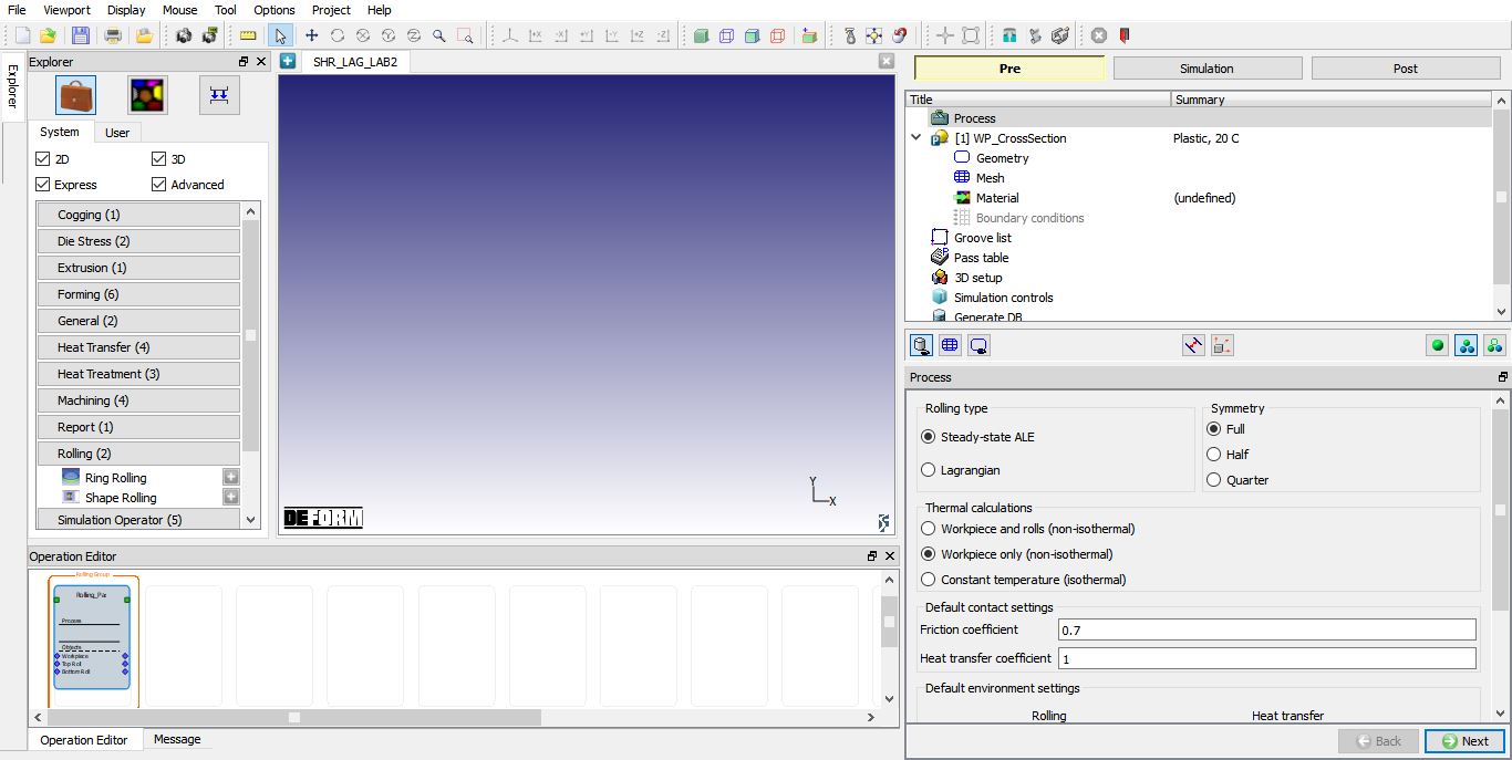
Adding Shape Rolling Operation from explorer
Set process conditions
In Process page, select the rolling type as “Lagrangian ” and symmetry type as “Full ”, as we will be setting up quarter symmetry object. As we are interested in temperature gradient in rolls, select the “Workpiece and rolls (non-isothermal) “ option. Define the friction coefficient value as 0.7 and heat transfer coefficient value as 11 as shown in Fig. L2.4.. Click ![]() to WP_CrossSection page.
to WP_CrossSection page.
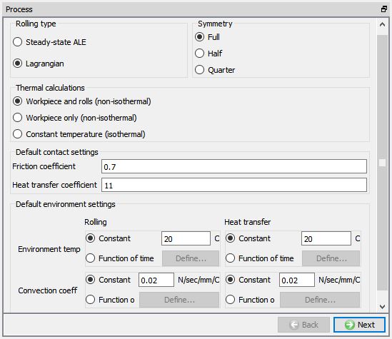
Defining rolling process conditions in Process page.
Defining Workpiece
Defining Workpiece object
In WP_CrossSection window, keep the object type as ‘Plastic’ and specify workpiece temperature as 100°C (See Fig. L2.5.). Click on ![]() to continue.
to continue.
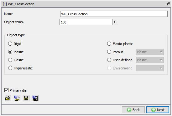
Workpiece Object Definition.
Creating Workpiece Geometry
We need to create a bar geometry for workpiece. To do so, in Geometry page select ![]() , from primitive geometry window select bar and define the parameters for Origin Point as (-50, -42.5), Width (W) as 100mm and Height (H) as 85mm as shown in Fig. L2.6. Click
, from primitive geometry window select bar and define the parameters for Origin Point as (-50, -42.5), Width (W) as 100mm and Height (H) as 85mm as shown in Fig. L2.6. Click ![]() to close. Click
to close. Click ![]() to Mesh.
to Mesh.
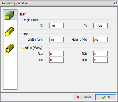
Define Primitive.
Generating Workpiece mesh
Generate the workpiece mesh with number of elements as 100 and keep other options to their default settings (See Fig. L2.7.). If required, expert mode is accessible when we click on ![]() button, to access more settings to control 2D mesh. Click
button, to access more settings to control 2D mesh. Click ![]() .
.
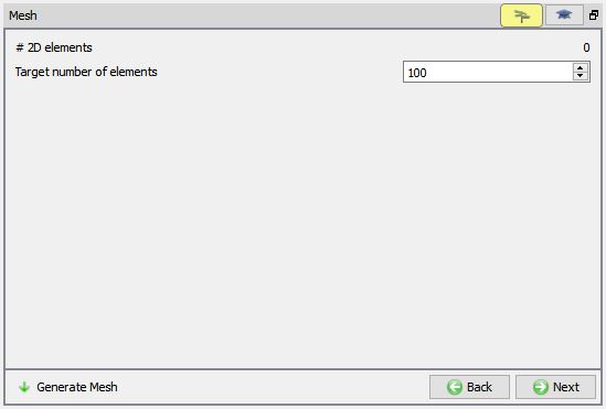
Workpiece mesh generation.
Assigning Workpiece material
To assign material for workpiece, select the steel category material ‘AISI-1045 ’ from material library and assign to workpiece. This can be done as shown in Fig. L2.8. Click on ![]() to BCC page.
to BCC page.
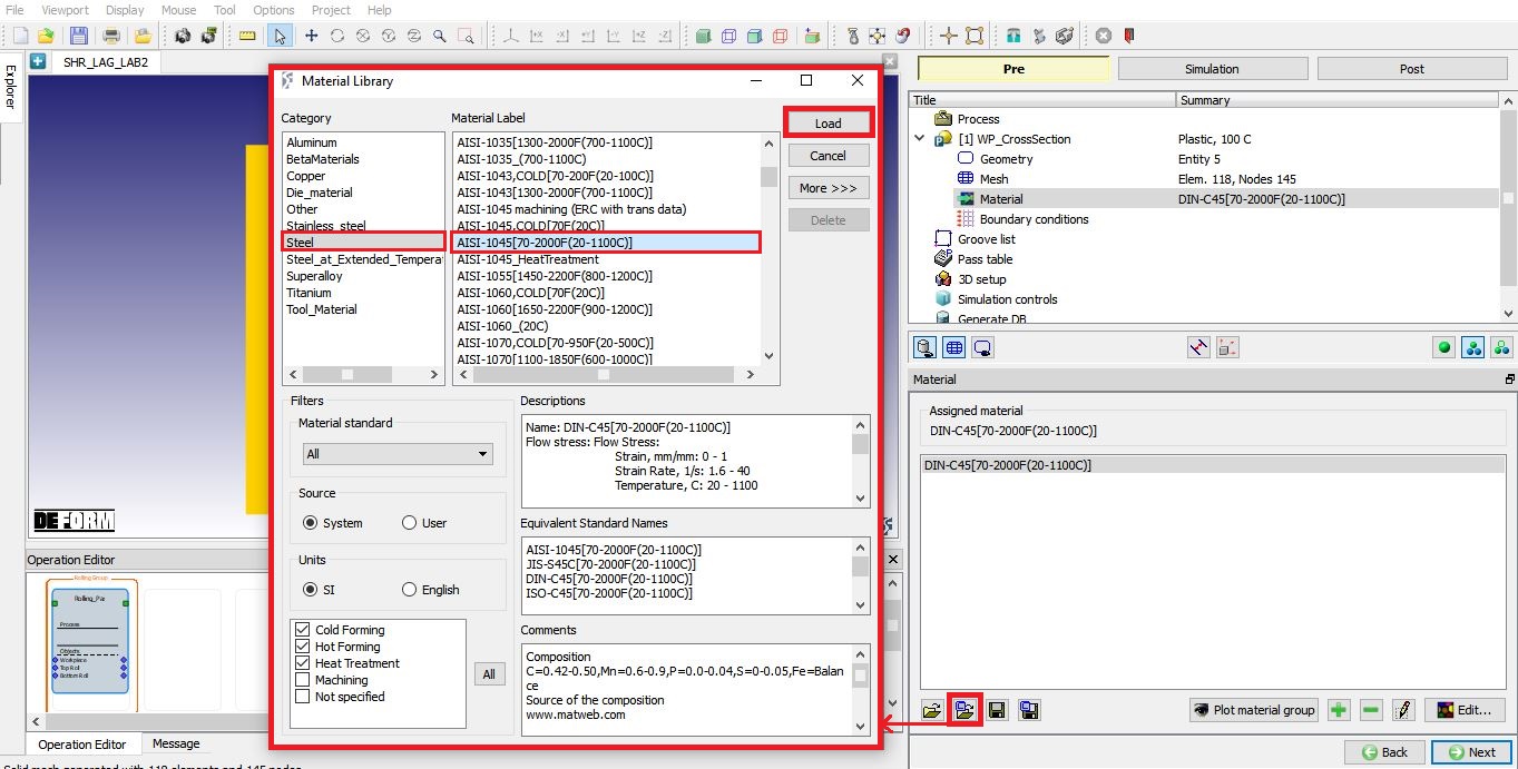
Assigning material to Workpiece.
Defining Workpiece boundary conditions
During the mesh generation the heat exchange with environment BCC is assigned to workpiece as shown in Fig. L2.9. Click on ![]() to Groove list page.
to Groove list page.
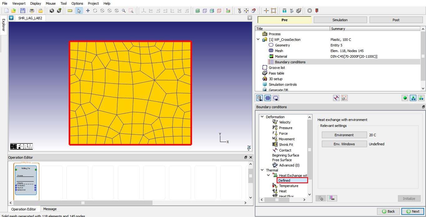
Workpiece boundary conditions page.
Defining Grooves
In Groove List page, we can define rolls 2D cross-section by clicking on the ![]() button. Click
button. Click ![]() thrice to add 3 grooves (See Fig. L2.10.), we will be using groove 1 for pass 1 and pass 2 and groove 2 & groove 3 for pass 3 and pass 4 (2-stands).
thrice to add 3 grooves (See Fig. L2.10.), we will be using groove 1 for pass 1 and pass 2 and groove 2 & groove 3 for pass 3 and pass 4 (2-stands).
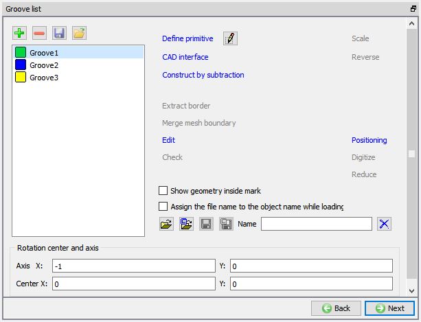
Groove list page.
Defining Grooves for Roll geometry
Select the First groove and click on ![]() to select the groove from one of the existing Roll groove primitives.
to select the groove from one of the existing Roll groove primitives.
Roll Groove Primitive page will be opened, select Flat rolls. Define 2D Cross-section geometry of roll grooves with width (W) as 120, radius (r1) as 5 and Roll Radius (RR) as 100 as shown in the Fig. L2.11. Click ![]() to close the Roll Groove Primitive page.
to close the Roll Groove Primitive page.
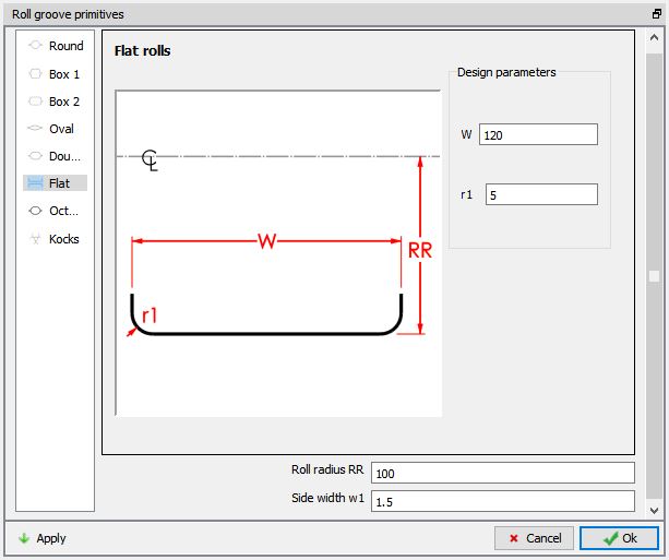
Defining Groove 1 Geometry
Similarly select the second groove and click on ![]() , then select Flat rolls. Define 2D Cross-section geometry of roll grooves with width (W) as 60, radius (r1) as 5 and Roll Radius (RR) as 100 as shown in the Fig. L2.12. Click
, then select Flat rolls. Define 2D Cross-section geometry of roll grooves with width (W) as 60, radius (r1) as 5 and Roll Radius (RR) as 100 as shown in the Fig. L2.12. Click ![]() to close the Roll Groove Primitive page.
to close the Roll Groove Primitive page.

Defining Groove 2 Geometry
Similarly select the third groove and click on ![]() , then select Flat rolls. Define 2D Cross-section geometry of roll grooves with width (W) as 120, radius (r1) as 5 and Roll Radius (RR) as 50 as shown in the Fig. L2.13. Click
, then select Flat rolls. Define 2D Cross-section geometry of roll grooves with width (W) as 120, radius (r1) as 5 and Roll Radius (RR) as 50 as shown in the Fig. L2.13. Click ![]() to close the Roll Groove Primitive page. Click
to close the Roll Groove Primitive page. Click ![]() to Pass page.
to Pass page.
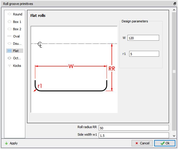
Defininig Groove 3 Geometry
Defining 4 passes with 2 Stands in 3rd and 4th pass
In pass table, using the ![]() button, add 4 passes. At all four passes, keep
button, add 4 passes. At all four passes, keep
-
Rollset type as vertical for all 4 passes.
-
Set Roll temperature as 40C for all for passes.
-
Define Roll speed as 50 rpm for all four passes.
Define Groove1 as Top roll groove geometry for 1st and 2nd passes and Groove2 as Top roll groove geometry for 3rd and 4th passes. Define Roll gap (mm) as 80mm , 75mm , 65mm and 60mm for 1st, 2nd , 3r d and 4th passes respectively. Turn ON the Reverserolling check box for 2nd and 4th passes as shown in the the Fig. L2.14.
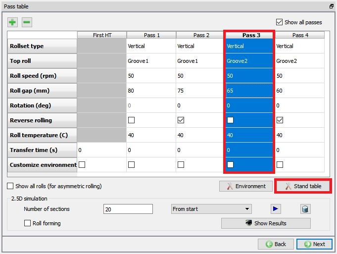
Pass Table
Select the Pass 3 and click on ![]() button as shown in the Fig. L2.14. to display stand table. In stand table, using the
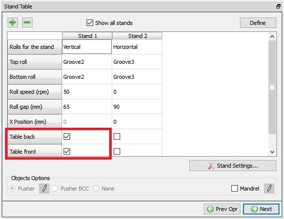
button as shown in the Fig. L2.14. to display stand table. In stand table, using the ![]() button add 2nd stand and define the 2nd stand parameters as shown in the Fig. L2.15.
button add 2nd stand and define the 2nd stand parameters as shown in the Fig. L2.15.
-
Define Rollset type as horizontal for 2nd stand.
-
Select Groove3 as groove geometry for Top roll at 2nd stand.
-
Define Roll speed (rpm) as 0rpm.
-
Define Roll gap (mm) as 90mm.
-
Set Roll temperature as 40C at 2nd stand.
-
Define X position (mm) as 0mm.
Click ![]() to close Stand table settings page.
to close Stand table settings page.
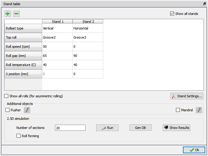
Defining 2 stands in Stand Table for third pass
Similarly, select the Pass 4 and click on ![]() button.
button.
In stand table, using the ![]() button add 2nd stand and define the 2nd stand as shown in the Fig. L2.16.
button add 2nd stand and define the 2nd stand as shown in the Fig. L2.16.
-
Define Rollset type as horizontal for 2nd stand.
-
Select Groove3 as groove geometry for Top roll at 2nd stand.
-
Define Roll speed (rpm) as 0rpm.
-
Define Roll gap (mm) as 90mm.
-
Set Roll temperature as 40C at 2nd stand.
-
Define X position (mm) as 0mm.
Click ![]() to close Stand table settings page. Leave other settings in Pass table as default and click
to close Stand table settings page. Leave other settings in Pass table as default and click ![]() to 3D setup page.
to 3D setup page.
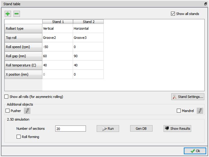
Defining 2 stands in Stand Table for fourth pass
Generating 3D Setup
In 3D setup page, we have options to set geometry and mesh settings for Workpiece, Rolls and Pusher that are applied to all passes and stands. Using the ![]() button adjacent to the respective objects, we can modify the settings. In this lab, select the “Prevent twisting ” check box if it is not selected by default as shown in Fig. L2.17.
button adjacent to the respective objects, we can modify the settings. In this lab, select the “Prevent twisting ” check box if it is not selected by default as shown in Fig. L2.17.
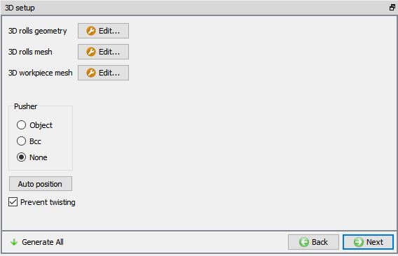
3D Setup page.
3D Roll geometry settings
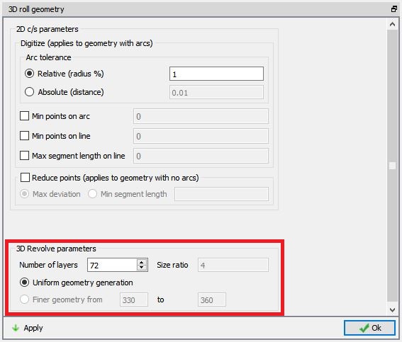
Click on ![]() button of 3D Rolls geometry, 3D roll geometry window will be opened with settings for 3D roll geometry. Define number of layers for rolls as 72 using the “Uniformgeometry generation ” option as shown in Fig. L2.18. Click on
button of 3D Rolls geometry, 3D roll geometry window will be opened with settings for 3D roll geometry. Define number of layers for rolls as 72 using the “Uniformgeometry generation ” option as shown in Fig. L2.18. Click on ![]() button to generate rolls with defined settings for all the passes and stands. Click on
button to generate rolls with defined settings for all the passes and stands. Click on ![]() button to close the 3D roll geometry window.
button to close the 3D roll geometry window.
3D Roll Geometry settings page
3D Roll mesh settings
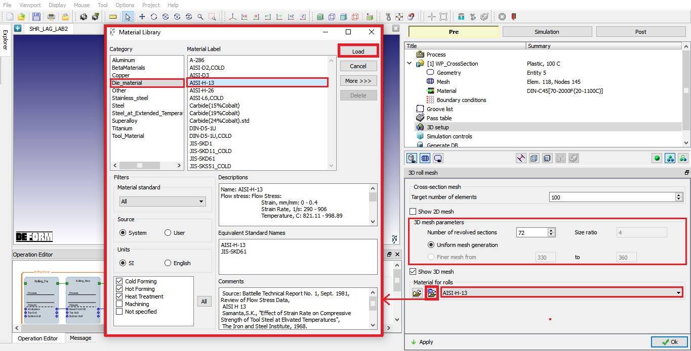
Click on ![]() button of 3D rolls mesh, 3D roll mesh window will be opened with settings for 3D roll mesh. Define number of revolved sections for rolls as 72 using the “Uniform mesh generation ” option and import the die material ‘AISI-H-13’ from material library to assign to rolls as shown in Fig. L2.19. Click on
button of 3D rolls mesh, 3D roll mesh window will be opened with settings for 3D roll mesh. Define number of revolved sections for rolls as 72 using the “Uniform mesh generation ” option and import the die material ‘AISI-H-13’ from material library to assign to rolls as shown in Fig. L2.19. Click on ![]() button to generate mesh for rolls with defined settings for all passes and stands and assign material. Click on
button to generate mesh for rolls with defined settings for all passes and stands and assign material. Click on ![]() button to close the 3D roll mesh window.
button to close the 3D roll mesh window.
3D Roll mesh settings page
3D Workpiece setup using Brick mesh
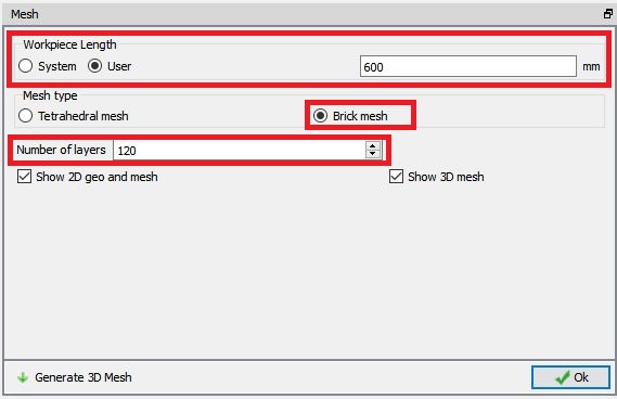
Click on ![]() button of 3D Workpiece, Mesh window with 3D Workpiece mesh settings will be opened. Select user radio button for Workpiece Length and define the length as 600mm , define Number of Layers as 120 using “Uniformthickness of layers ” option to generate uniform mesh as shown in the Fig. L2.20. For lagrangian setup we will be having only the Boolean meshing method available. Click on
button of 3D Workpiece, Mesh window with 3D Workpiece mesh settings will be opened. Select user radio button for Workpiece Length and define the length as 600mm , define Number of Layers as 120 using “Uniformthickness of layers ” option to generate uniform mesh as shown in the Fig. L2.20. For lagrangian setup we will be having only the Boolean meshing method available. Click on ![]() to generate 3D Workpiece mesh. Click
to generate 3D Workpiece mesh. Click ![]() to close the Mesh window of Workpiece mesh settings after generating the mesh.
to close the Mesh window of Workpiece mesh settings after generating the mesh.
3D Workpiece mesh settings page
Pusher definition
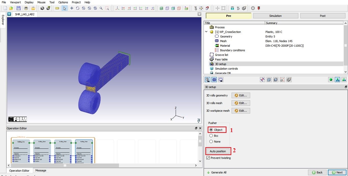
In 3D setup page, we can select the pusher as object or BCC. In this lab setup, we will be using the pusher as object so, select “Object ” radio button and click on ![]() button as shown in the Fig. L2.21. to position Workpiece with respect to rolls depending on the rolls movement direction and Pusher to Workpiece. Click
button as shown in the Fig. L2.21. to position Workpiece with respect to rolls depending on the rolls movement direction and Pusher to Workpiece. Click ![]() to simulation controls page.
to simulation controls page.
Pusher object definition in 3D setup page.
Simulation controls in rolling group level
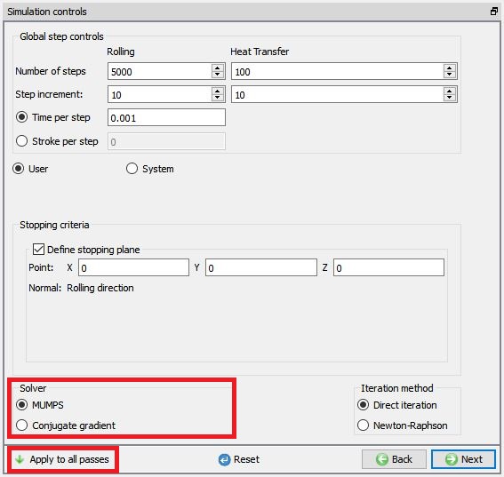
In this simulation controls page we need to select the solver as MUMPS since we are using the horizontal rolls having torsion movement in the 3rd and 4th pass. After selecting the solver, click on ![]() button. Now save the project and select the Rolling Pass operation 1 in operation editor by clicking on the operation tile to modify settings of Pass 1.
button. Now save the project and select the Rolling Pass operation 1 in operation editor by clicking on the operation tile to modify settings of Pass 1.
Simulation controls in rolling group level
Modifying Rolling pass operation 1 (Pass 1)
Rolling pass operation
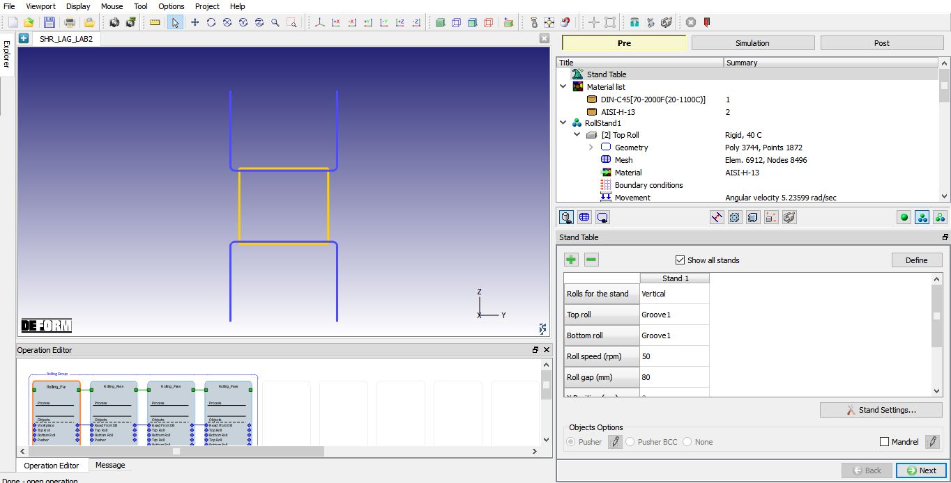
As you select the Rolling Pass operation 1, Stand table page will appear as shown in Fig. L2.23. which shows the Pass 1 data.
Stand table for pass 1
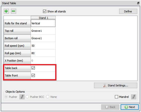
We need to use the Tableback and Tablefront in this lab, so turn on the check box as shown in the Fig. L2.24. As mesh is generated and material is assigned for rolls, click ![]() until Table (Back) page.
until Table (Back) page.
Stand table for Pass 1
Table (Back)
In Table (Back) page, accept the default temperature and click ![]() .
.
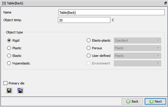
Table (back) page
Defining Table back geometry
In Table back geometry page, select the ‘Define primitive’ and define the parameters as mentioned below for back Table geometry.
Origin Point X = -50mm
Width W = 100mm
Height H = 5mm
Length = 750
Check “Align to the top of bottom roll for strip rolling” check box
Pass Line = 2.5mm.
Click ![]() to create table and
to create table and ![]() to close the Table/Guide geometry Primitive page and click
to close the Table/Guide geometry Primitive page and click ![]() to mesh page.
to mesh page.
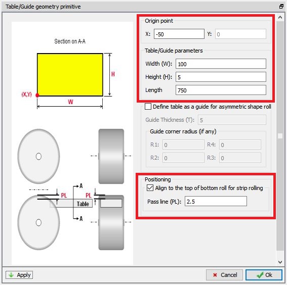
Back Table Geometry creation
Table back Mesh Generation
Switch to Expert mode by clicking on ![]() , then define the Uniform Thickness number of layers as 5 and keep the rest of the settings as default. Click on
, then define the Uniform Thickness number of layers as 5 and keep the rest of the settings as default. Click on ![]() to generate mesh for the Table.
to generate mesh for the Table.
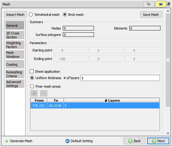
Back Table mesh generation
Table Back Material assigning
To assign material for back Table, select the material ‘AISI-H-13 ’ from material window. This can be done as shown in Fig. L2.28. Click on ![]() until Table Front page.
until Table Front page.
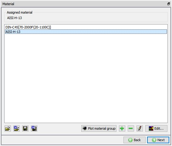
Table back material Assigning
Define the Table Front as Table back with same settings for the geometry, mesh and material.
Pusher object
The Pusher object is created automatically using the workpiece dimensions. Click ![]() to check the created geometry and assigned movement controls.
to check the created geometry and assigned movement controls.
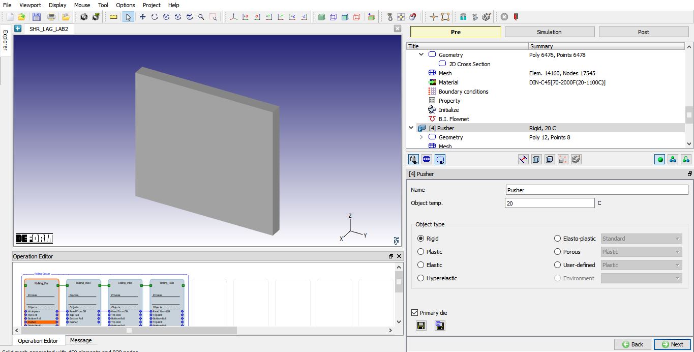
Pusher object page
Pusher object movement definition
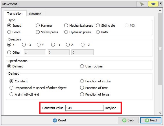
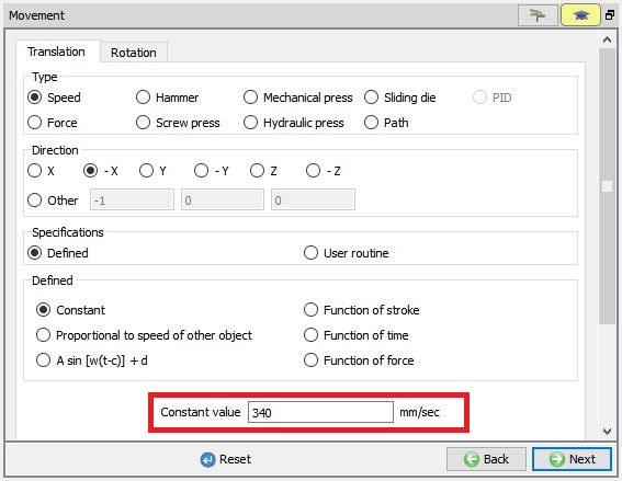
Select Speed option. Speed of the pusher should be 50 to 60% of the relative velocity of the rolls and hence assign a constant speed of 340 mm/sec for pusher as shown in Fig. L2.30. The preview of the movement can be seen by clicking on the “Preview Movement” option. Click ![]() to Object Positioning page.
to Object Positioning page.
Pusher object movement definition
Object positioning
The objects are automatically positioned correctly when we click ![]() button in the 3D setup page and the Table front and table back are created at proper position automatically so, we don’t need to do any positioning now. The objects positioned should appear as shown in Fig. L2.31.
button in the 3D setup page and the Table front and table back are created at proper position automatically so, we don’t need to do any positioning now. The objects positioned should appear as shown in Fig. L2.31.
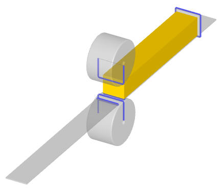
Position of the objects
Defining Contact Relations
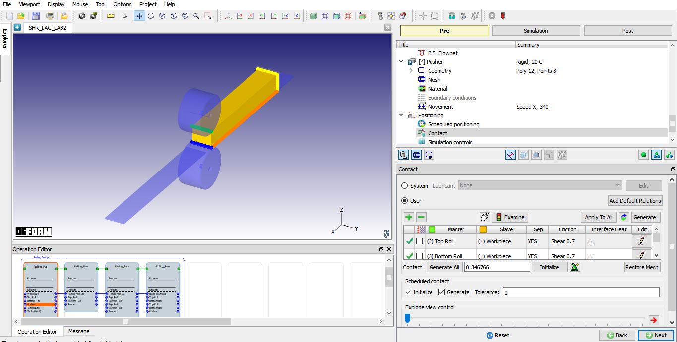
In the Contact page, master-slave relations will be automatically added between rolls and Workpiece. Select the first relation and define the Shear friction as 0.7 and Interface heat transfer coefficient as 11(See Fig. L2.32.) using ![]() button. Using
button. Using ![]() button, we will apply same frictional conditions between all stands Top Rolls and Workpiece. Click the
button, we will apply same frictional conditions between all stands Top Rolls and Workpiece. Click the ![]() to determine an intelligent contact tolerance and click on the
to determine an intelligent contact tolerance and click on the ![]() button to generate contacts between objects. Click
button to generate contacts between objects. Click ![]() to Simulation controls page.
to Simulation controls page.
Contact generation.
Defining Simulation Controls
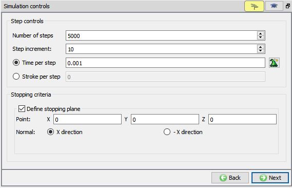
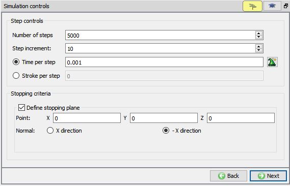
In simulation controls page, switch to guided mode by clicking on ![]() , then set Number of steps as 5000 for this simulation with astep increment to save as 10 and Time per step as 0.001 sec. For stopping criteria, use default stopping plane point and select X direction. Click
, then set Number of steps as 5000 for this simulation with astep increment to save as 10 and Time per step as 0.001 sec. For stopping criteria, use default stopping plane point and select X direction. Click ![]() to generate database.
to generate database.
Simulation controls.
Generating Database
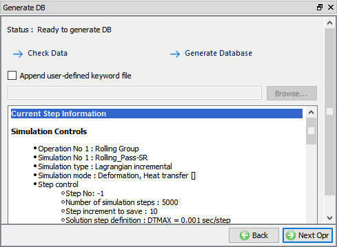
In the database generation page, user can check the data required for the analysis and proceed to generate the database (See Fig. L2.34.).
Database Generation
Modifying Rolling pass operation 2 (Pass 2)
Now save the project and select the Rolling Pass operation 2 in operation editor by clicking on the operation tile to modify settings of pass 2. We need to use tables at back and front in pass 2, so turn on Table back and Table front check boxes in pass2 stand table as shown in Fig. L2.24. Click ![]() until the Top Roll mesh page.
until the Top Roll mesh page.
Creating the table geometry and generating mesh
Similarly create the table geometry, generate mesh and assign material for both the table back and table front as mentioned in 2.9.2
Pusher object movement definition
In pusher movement page define the direction of the pusher object as-X direction and constant speed as 340mm/sec as shown in the Fig. L2.35.
Pusher movement definition
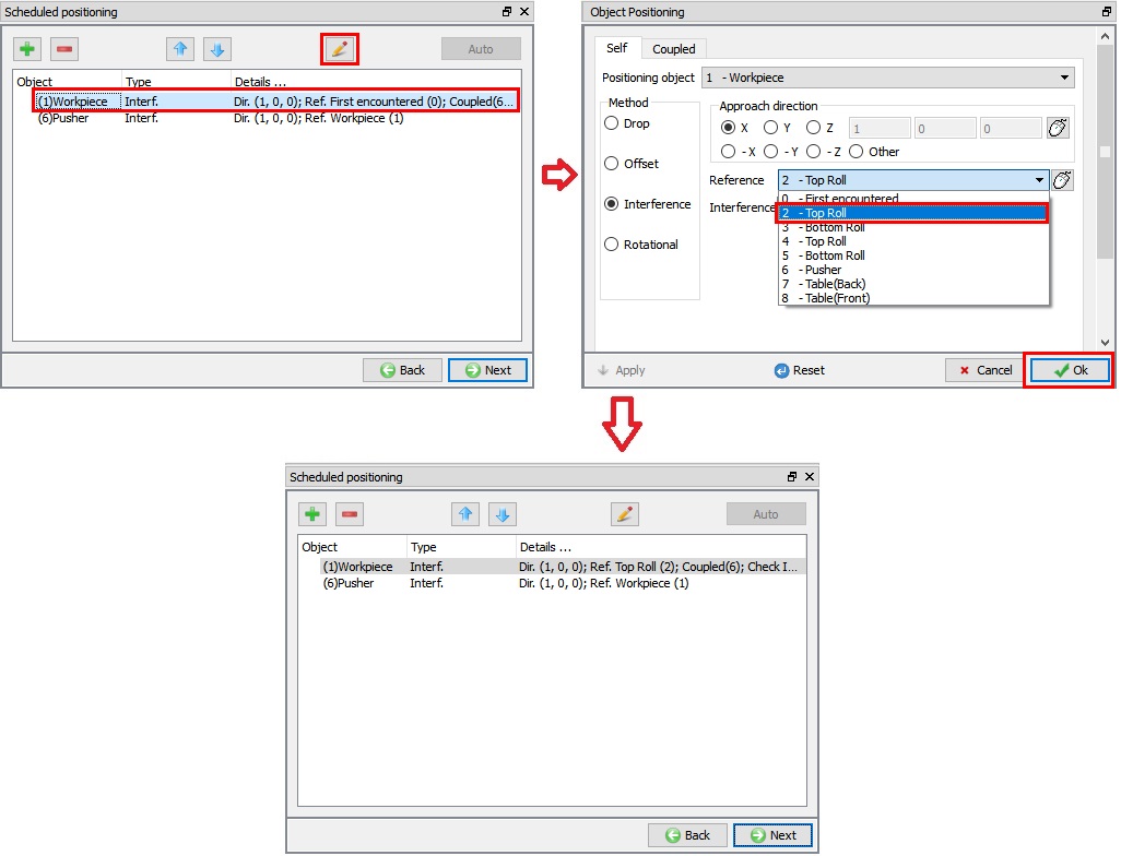
Schedule positioning definition
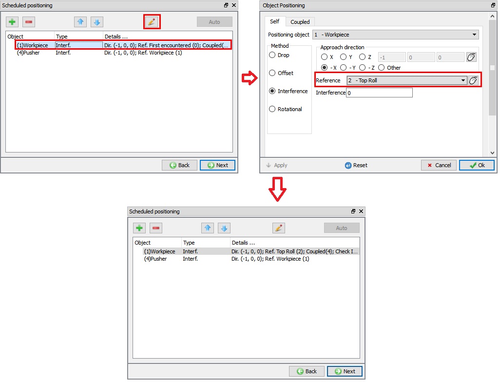
In schedule positioning page select the first relation and click on edit button, then change thereference object as Top roll from first encounter and use the default approach direction as -X. click ![]() button as shown in the Fig. L2.36.
button as shown in the Fig. L2.36.
Schedule positioning definition
Simulation controls page
In simulation controls, switch to guided mode by clicking on ![]() , when clicked on the Apply to all passes in the rolling group simulation controls, for each pass the normal direction will be defined by default depending on the reverse rolling check box status. For this pass, the normal direction should be-X direction as shown in the Fig. L2.37. Select the Rolling Pass operation 3 in operation editor by clicking on the operation tile to modify settings of Pass 3.
, when clicked on the Apply to all passes in the rolling group simulation controls, for each pass the normal direction will be defined by default depending on the reverse rolling check box status. For this pass, the normal direction should be-X direction as shown in the Fig. L2.37. Select the Rolling Pass operation 3 in operation editor by clicking on the operation tile to modify settings of Pass 3.
Simulation controls page
Modifying Rolling pass operation 3 (Pass 3)
We have two stands in Pass 3. We will be using tables at front and back for Stand1, so turn on checkboxes of Table back and Tablefront of Stand1 as shown in the Fig. L2.38. Click ![]() until RollStand1 Top Roll mesh page.
until RollStand1 Top Roll mesh page.
Stand table for pass 3
Creating the table geometry and generating the mesh
In Table back page, accept the default 20C temperature and click ![]() to geometry page. In Table back geometry page, select the
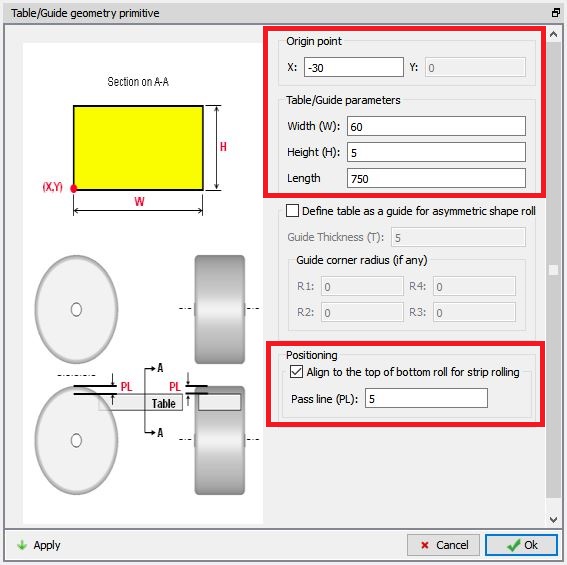
to geometry page. In Table back geometry page, select the ![]() and define the parameters as mentioned below for back Table geometry.
and define the parameters as mentioned below for back Table geometry.
Origin Point X = -30mm
Width W = 60mm
Height H = 5mm
Length = 750mm
Check “Align to the top of bottom roll for strip rolling” check box
Pass Line = 5mm.
Click ![]() to create table and
to create table and ![]() to close the Table/Guide geometry primitive page and click
to close the Table/Guide geometry primitive page and click ![]() to Mesh page.
to Mesh page.
Back Table Geometry creation
In mesh page, switch to expert mode by clicking on ![]() , then define the Uniform Thickness number of layers as 5 and keep the rest of the brick mesh settings as default. Click on
, then define the Uniform Thickness number of layers as 5 and keep the rest of the brick mesh settings as default. Click on ![]() to generate mesh for the Table as shown in Fig. L2.27.
to generate mesh for the Table as shown in Fig. L2.27.
Assign ‘AISI-H-13 ’ material for the table back object from material window. This can be done as shown in Fig. L2.28. Click on ![]() until Table Front page.
until Table Front page.
Similarly define the Table Front as Table back with same settings for the geometry, mesh and material.
Defining the movement controls for stand2 rolls
For rolls, the mesh is already generated and material is assigned so, click ![]() to movement page. Switch to guided mode by clicking on
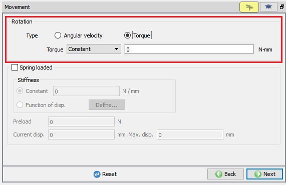
to movement page. Switch to guided mode by clicking on ![]() , then define the rotation type as “Torque ” with constant 0 N-mm as shown in the Fig. L2.40.
, then define the rotation type as “Torque ” with constant 0 N-mm as shown in the Fig. L2.40.
Stand2 top roll movement page
Similarly, define the movement controls even for the bottom roll.
Pusher object movement definition
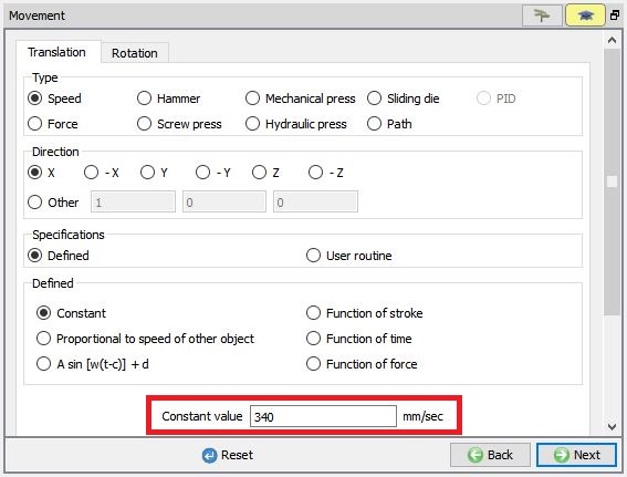
In pusher movement page, switch to expert mode by clicking on ![]() , then define the direction of the pusher object as X direction and constant speed as 340mm/sec as shown in the Fig. L2.41.
, then define the direction of the pusher object as X direction and constant speed as 340mm/sec as shown in the Fig. L2.41.
Pusher object movement page for pass 3
Schedule positioning definition
In schedule positioning page select the first relation and click on edit button, then change the reference object as 2 - Top roll of roll stand1 from first encounter and use the default approach direction as X. Click ![]() button as shown in the Fig. L2.42.
button as shown in the Fig. L2.42.
Schedule positioning definition
Simulation controls page
In simulation controls, switch to guided mode by clicking on ![]() , by default when we click on the
, by default when we click on the ![]() in rolling group simulation controls for each pass the normal direction will defined by default depending on the roll direction. In the pass the normal direction should be X direction. Select the Rolling Pass operation 4 in operation editor by clicking on the operation tile to modify settings of pass 4.
in rolling group simulation controls for each pass the normal direction will defined by default depending on the roll direction. In the pass the normal direction should be X direction. Select the Rolling Pass operation 4 in operation editor by clicking on the operation tile to modify settings of pass 4.
Modifying Rolling pass operation 4 (Pass 4)
We have two stands in Pass 4. We will be using tables at front and back for Stand1, so turn on checkboxes of Table back and Table front of Stand1 similarly as shown in the Fig. L2.39. Click ![]() until Table (Back) page.
until Table (Back) page.
Creating the table geometry and generating the mesh
Similarly create the table geometry, generate mesh and assign material for both the table back and table front as mentioned in the 2.11.1.
Defining the movement controls for stand2 rolls
Since the mesh is already generated and material is assigned for rolls, click ![]() to movement page. Define the rotation type as “Torque ” with constant 0 N-mm similarly as 2.11.3. for both top and bottom roll.
to movement page. Define the rotation type as “Torque ” with constant 0 N-mm similarly as 2.11.3. for both top and bottom roll.
Pusher object movement definition
In pusher movement page, similar to 2.10.2. define the direction of the pusher object as -X direction and constant speed as 340mm/sec.
Schedule positioning definition
Similar to 2.10.3 in schedule positioning page select the first relation and click on edit button, then change the reference object as 2 - Top roll of roll stand1 from first encounter and use the default approach direction as -X.
Simulation controls page
In simulation controls, switch to guided mode by clicking on ![]() , by default when we click on the
, by default when we click on the ![]() in rolling group simulation controls for each pass the normal direction will defined by default depending on the roll direction. In this pass the normal direction should be -X direction and use the default stopping plane point.
in rolling group simulation controls for each pass the normal direction will defined by default depending on the roll direction. In this pass the normal direction should be -X direction and use the default stopping plane point.
Running simulation
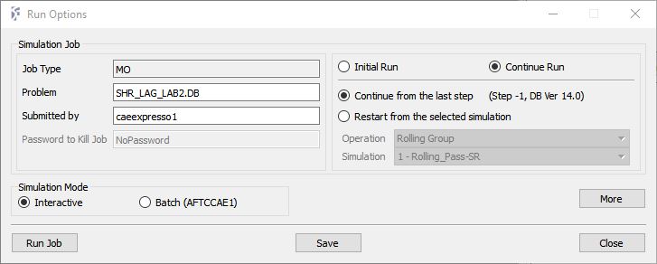
Once the database has been generated switch to the Simulation mode by clicking on ![]() button above the operation tree. Click on the
button above the operation tree. Click on the ![]() action label to open the Run Options dialog as shown in Fig. L2.43. Use the default ContinueRun option to select “Continue from the last step ” (from step -1) option and then select the Simulation mode as Interactive radio button. Click on
action label to open the Run Options dialog as shown in Fig. L2.43. Use the default ContinueRun option to select “Continue from the last step ” (from step -1) option and then select the Simulation mode as Interactive radio button. Click on ![]() button to run the simulation.
button to run the simulation.
To define MPI settings, click on ![]() button, Run Options window will expand and displays options to define MPI settings for simulation (max number of processors that can be defined depend on your 3D MPI license).
button, Run Options window will expand and displays options to define MPI settings for simulation (max number of processors that can be defined depend on your 3D MPI license).
Run Simulation Popup.
Monitor the progress of the simulation by looking at the Simulation Message and Simulation Log tab, making sure that the ![]() option is checked. User can view the rolling process as the simulation proceeds from Simulation graphics
option is checked. User can view the rolling process as the simulation proceeds from Simulation graphics
Simulation will stop after reaching steady state with a below message in Message file.
“PROGRAM STOPPED!
Stopping plane: All nodes of Object 1 has exited the die/roll.”
Post Processing
After the simulation has completed, click on ![]() tab, MO post processor will open (as shown in Fig. L2.44.).
tab, MO post processor will open (as shown in Fig. L2.44.).
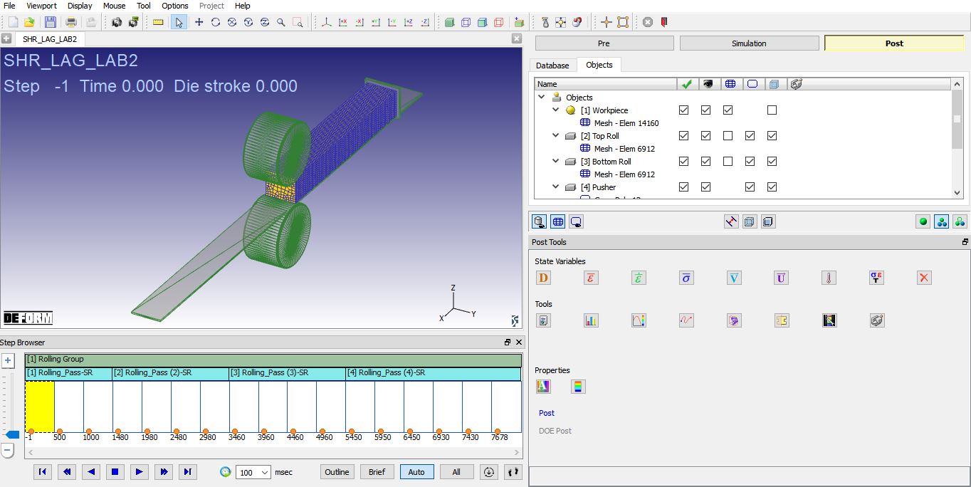
MO Post mode after simulation is completed.
Go to last step, plot Effective strain and Temperature state variables and observe the state variable distribution.
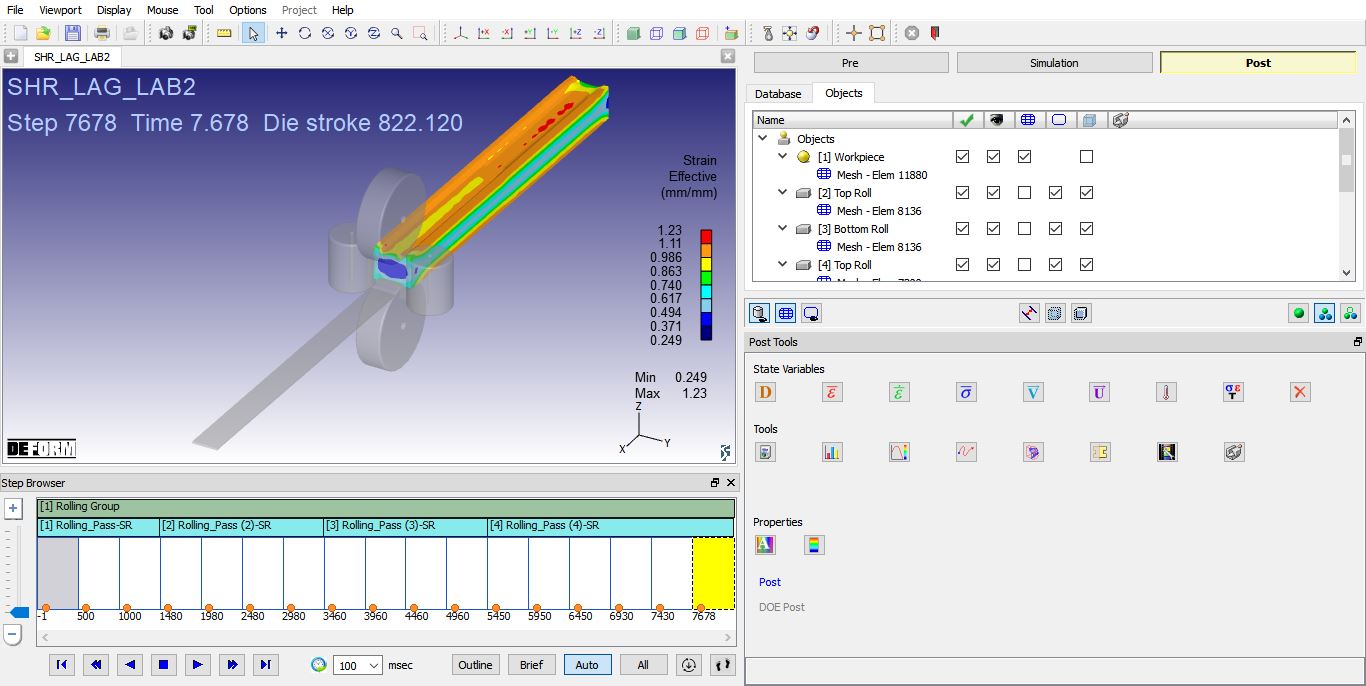
Effective strain distribution
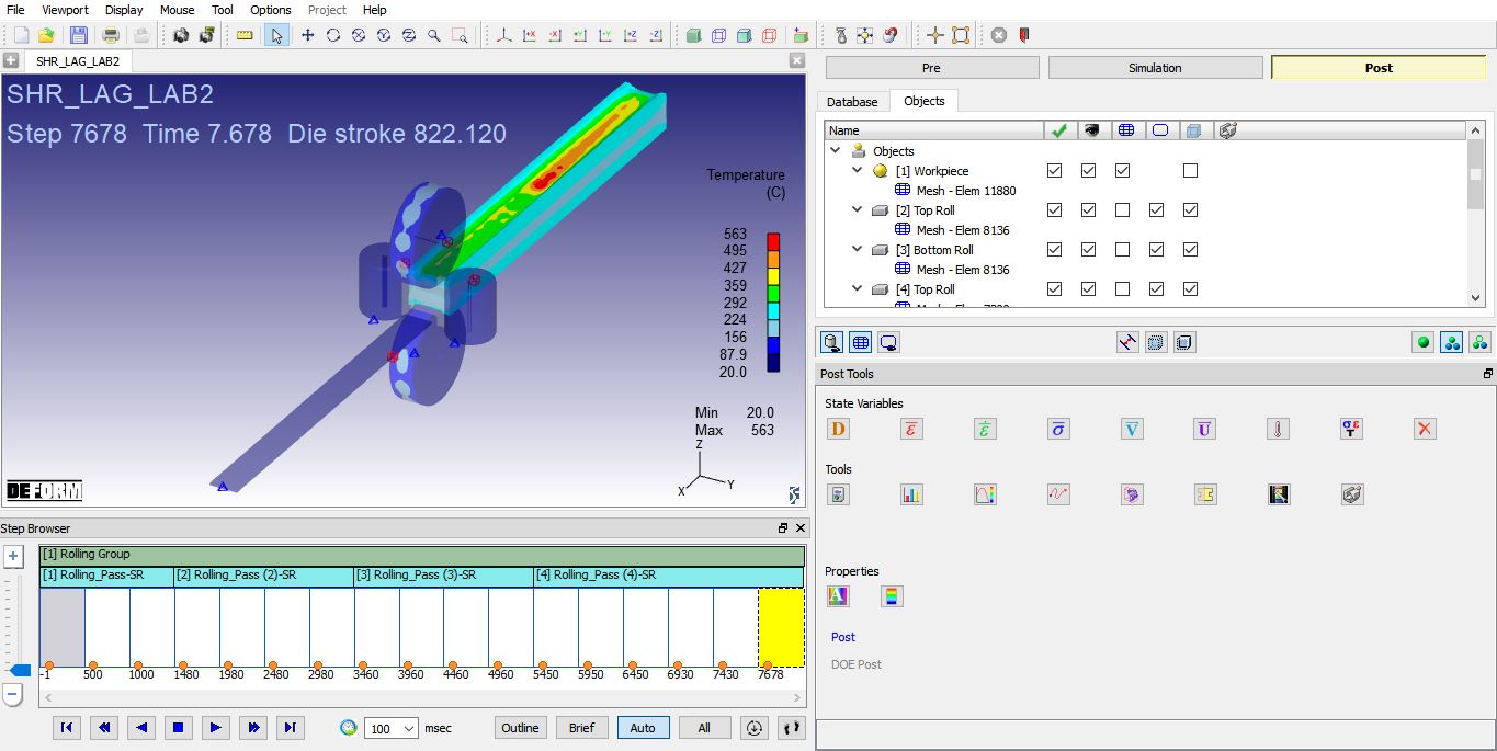
Temperature distribution