Appendix XX: How to do coupled die stress analysis for 3D models
*From QT3 interface
Starting from 3D V10.0+ the system supports a convenient way to carryout Multiple-time stepping (MTS) Die stress analysis. Current structure depends on a local DAT file (DEF_LCDSTS.DAT) to trigger these procedures. In a typical die stress analysis since fine mesh systems are needed on the die objects, models are memory intensive and need long computing time. Procedures developed in DEFORM allow user to specify different time step sizes for plastic workpiece (deformation) and elastic dies (die stress analysis), It helps in CPU cost saving. User can specify loosely coupled die stress analysis on elastic tools only at selected steps, rather than at every step. This gives a reasonable balance of coupled stress with efficient run (computational) times. The factor defines a ratio of multiple-time stepping like,
Currently the following requirements have to be met by the model to be able to use these analysis features.
-
The dies should be elastic and use tetrahedral mesh.
-
The dies should have movement conditions defined in the BCC dialogs.
-
The dies movement should be specified in the movement control dialogs.
There are several options for coupling the interactions of the workpiece and tool. In any way the model stores the results in the same database. Those are,
| Option | Solution Method | Stress Update | Geometry Update |
|---|---|---|---|
| 1 | Fully coupled | Die and workpiece | Die and workpiece |
| 2 | One way coupled | Die and workpiece | Die and workpiece |
| 3 | One way coupled | Die and workpiece | Workpiece only |
Coupling workpiece and tool interaction options
-
Fully coupled means the deflection of the tool is reflected in the deformation of the workpiece at the current step.
-
One way coupling means the stresses are calculated in the tool. If die geometry is updated, it will not be reflected in workpiece shape until the next step.
-
If option 3 is used, stress is calculated in the die, but the die geometry is never updated.
To activate loosely coupled die stress analysis, use a text editor such as notepad to create a file in the same directory as the database, named DEF_LCDSTS.DAT.
Contents of the DAT file are as follows:
Line 1: = Coupling option (1, 2 or 3)
= 1 for fully coupled
= 2 for one way coupled (die geometry is updated, it will not be reflected in workpiece shape until the next step)
= 3 for one way coupled (die geometry is never updated)
Line 2: = n, ratio of the time steps for Stress coupling (Δt_elastic_dies/Δt_plastic_workpiece).
Line 3: = m, thermal time step ratio for Temperature coupling (Δt_elastic_dies/Δt_plastic_workpiece).
For example:
Line 1 with entry 1, for Option 1 -Fully coupled option.
n = 5 in Line 2 indicates that the coupled calculations are computed every 5 steps, and every 5th step elastic object sees 5 times the step size compared to plastic workpiece.
m = 5 in Line 3 indicates time step size used by thermal computations is 5 times that of deformations computations.
So a typical DEF_LCDSTS.DAT file for option 1- Fully Coupled distress the text in file might look like,
1
5
5
Selection criteria for Die Stress analysis options:
Option 1 - In general, option 1 is the most accurate, and most computationally expensive. Option 3 is the least computationally expensive, and offers the most simplification of the process.
Option 2 - more numerically efficient than option 1, but may cause some inconsistencies in workpiece surface position (and therefore workpiece volume) if the change in the die shape is substantial.
Option 3 - If the only interest is tool stress, option 3 is generally adequate. If tool deflection is important option 1 or 2 should be selected.
For the Schematic setup as shown below, See Fig. 1, the die stress results are compared for all three options, See Fig. 2.
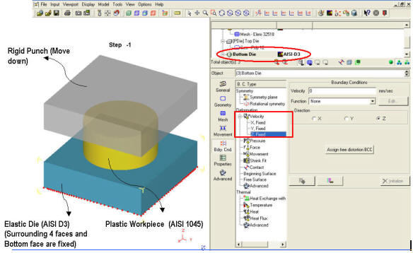
Simple Coupled die-stress problem setup for the bottom die
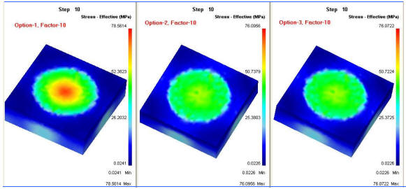
Die-stress result comparison for all three options at the same step
Related Topics: