3D Die stress Study Lab1
1.1. Introduction
1.2. Opening project file
1.3. Add Die Stress Study
1.4. Adding Objects
1.5. Top Die
1.6. Bottom Die
1.7. Simulation Controls
1.8. Generate Database
1.9. Post Processing
Introduction
The objective of this lab is to run a die stress analysis. When the stress analysis is being done on only one tool, a one step simulation is sufficient to get accurate stresses. When the stress analysis is being done on die assemblies where there is interaction between the tools, more than one step is typically needed for the die stack to come to a state of equilibrium under the applied load.
In a typical die stress simulation, the workpiece is removed and the forces exerted onto the dies by the workpiece are interpolated onto the tools.
Opening project file
Create a new problem either by selecting File![]() **New Problem** or by clicking the New Problem
**New Problem** or by clicking the New Problem ![]() icon. The Problem Setup window will appear. Select “Integrated Manufacturing Process “ radio button and units system as “English “ radio button to setup problem in English units system. Define Problem Name as “ Die_stress_Lab1 “ and make sure the “Show option dialog” check box is turned on (if we do not turn on the “Show option dialog ” check box, then we will not get the New Project dialog in MO UI). Click on
icon. The Problem Setup window will appear. Select “Integrated Manufacturing Process “ radio button and units system as “English “ radio button to setup problem in English units system. Define Problem Name as “ Die_stress_Lab1 “ and make sure the “Show option dialog” check box is turned on (if we do not turn on the “Show option dialog ” check box, then we will not get the New Project dialog in MO UI). Click on ![]() button to open a new Problem using the Deform Integrated Manufacturing Process.
button to open a new Problem using the Deform Integrated Manufacturing Process.

Problem defining window
MO wizard will open along with project naming window as shown in Fig. 3DDSL1.1., In the field of project name, set the project name as Die_stress_Lab1 , select the copy existing project radio button as we will be copying the existing project from Labs folder which will be used as the nominal setup. Select the source location browse button and import the Spike_Forging.moproj from installation path \SFTC\DEFORM\v_\3d\LABS, turn on the C**o py Database** check box, click ![]() to close the New project window. Spike_forging simulation will be imported to Die_stress_Lab1 project. (see Fig. 3DDSL1.2.). After loading the Spike forging operation , Generate Database in Heat transfer operation using
to close the New project window. Spike_forging simulation will be imported to Die_stress_Lab1 project. (see Fig. 3DDSL1.2.). After loading the Spike forging operation , Generate Database in Heat transfer operation using ![]() option. After generating database, switch to (Simulation)
option. After generating database, switch to (Simulation) ![]() mode and simulate it using
mode and simulate it using ![]() option. After completion of simulation, switch to
option. After completion of simulation, switch to ![]() mode.
mode.
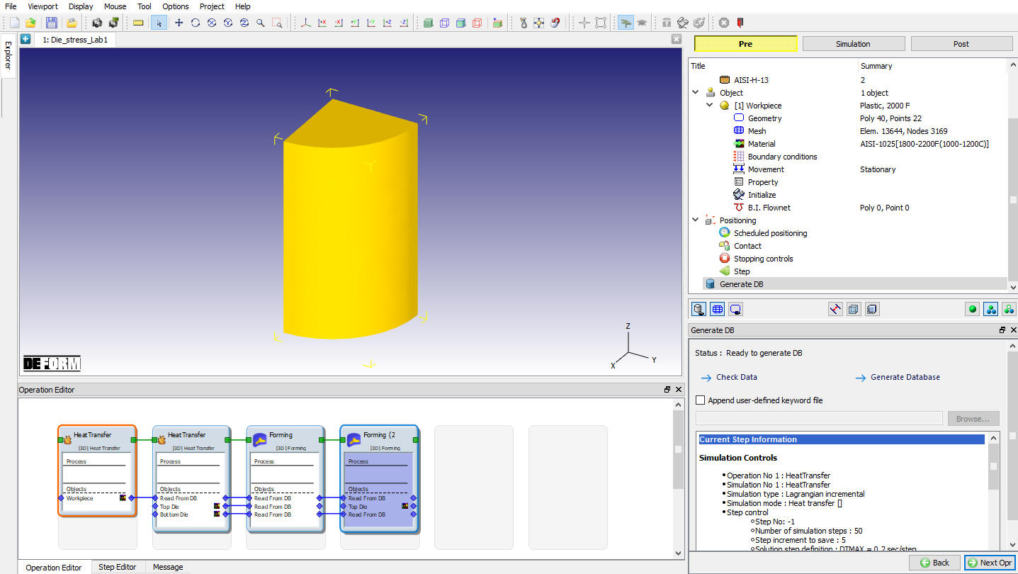
Project imported
We will be executing die stress analysis at the end of First forming operation.
Add Die Stress Study
At top Left corner of the Display window, Left mouse click on ![]() button and select Add Die stress Study operation as shown in Fig. 3DDSL1.3.
button and select Add Die stress Study operation as shown in Fig. 3DDSL1.3.
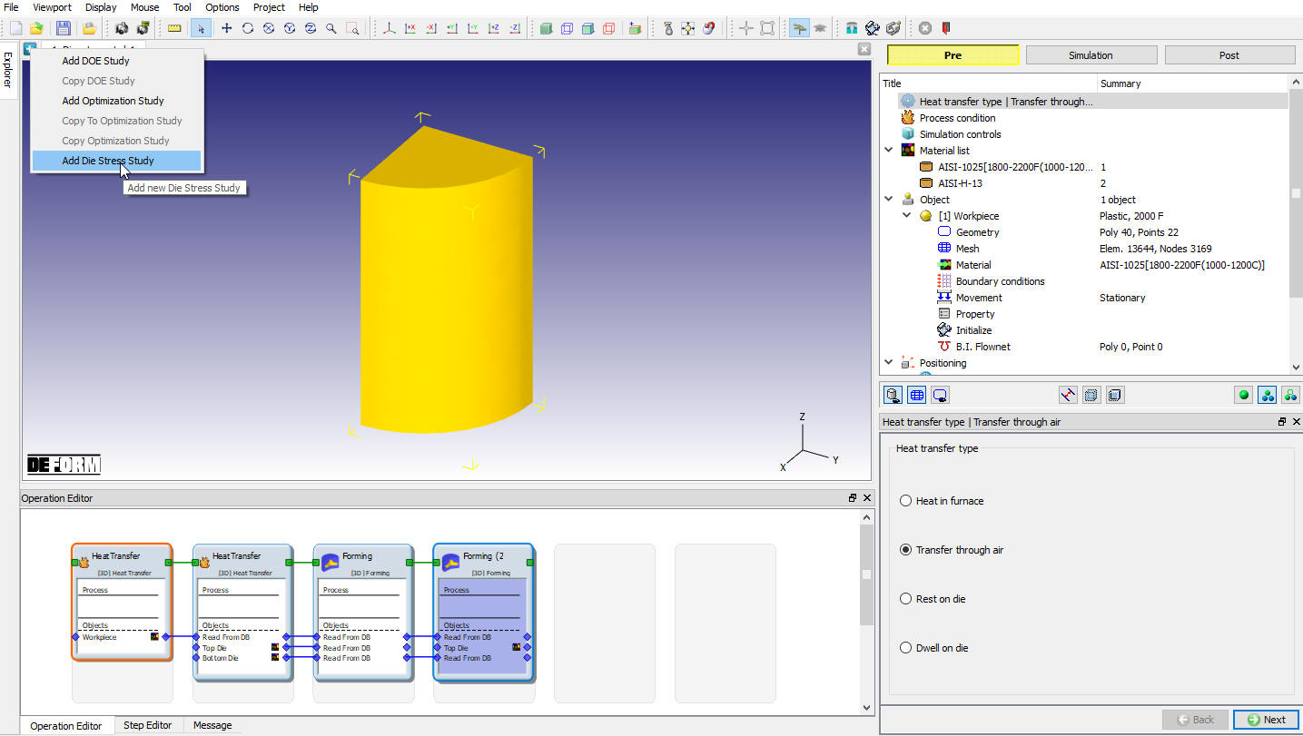
Adding Diestress study
To perform Die stress analysis at the end of first forming operation, select “Load step from DB ” and then select last step of the 3rd operation (step 90) in Step selection page as shown in Fig. 3DDSL1.4. Click ![]() .
.
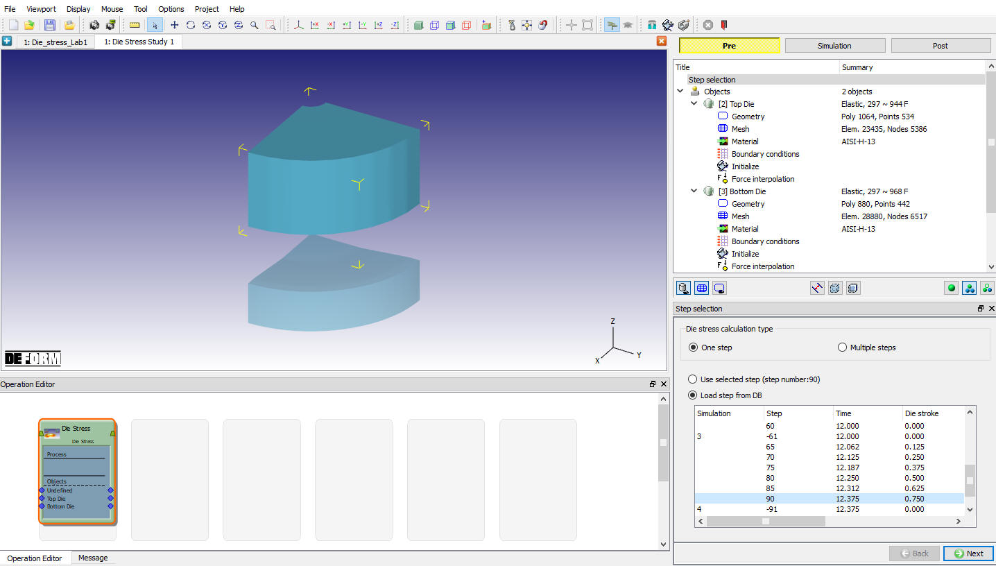
Step selection page
Adding Objects
For this lab, we do not require any extra objects. So, keep default Top die and Bottom die as shown in Fig. 3DDSL1.5., click ![]() .
.
Accept object type as Elastic, generate mesh with default number of elements and click ![]() until Top die object page.
until Top die object page.

Objects page
Top Die
Top Die object definition
By default, the object type of rigid objects from the loaded step will be changed to elastic. Keep the object type as elastic for the Top Die object. From v13.1.1, two new options have been introduced in the object page to position the dies in future steps for Multiple steps die stress analysis, we need not use these options for single step die stress analysis hence, keep the Need positioning check box turned off.
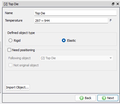
Top Die object page
Assign Material
In material window, select AISI-H-13 material inherited from nominal simulation as shown in Fig. 3DDSL1.7. and click ![]() .
.

Material Window
Assigning Boundary Conditions
-
Select the Symmetryplaneboundarycondition , and then add a boundary condition to each of the Top Die symmetry planes as shown in Fig. 3DDSL1.8.
-
Apply a Vz = 0 Velocityboundarycondition on the top surface of the Top Die. This boundary condition prevents the die from flying off when the forces are applied. (See Fig. 3DDSL1.9.)

Assigning Symmetry Boundary conditions

Assigning Velocity BCC
Interpolate Forces for Top die
In Force interpolation page, click on ![]() action label and after interpolation, we are able to see force interpolated messages in the property editor page as shown in Fig. 3DDSL1.10. Click
action label and after interpolation, we are able to see force interpolated messages in the property editor page as shown in Fig. 3DDSL1.10. Click ![]() .
.

Top Die Force Interpolation window
Bottom Die
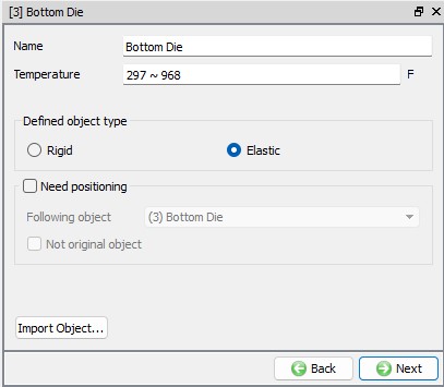
Bottom Die object Definition
We will keep the object type as Elastic for the Bottom Die and turn off Need positioning check box. Generate mesh with default number of elements and click ![]() until Bottom die material page.
until Bottom die material page.
Bottom Die object page
Assign Material
In material window, select AISI-H-13 material as shown in Fig. 3DDSL1.12. and click ![]() .
.
Material Window
Assigning Boundary Conditions
-
Select the Symmetry plane boundary condition, and then add a boundary condition to each of the symmetry surfaces as shown in Fig. 3DDSL1.13.
-
Apply a Vz = 0 Velocity boundary condition on the bottom surface of the bottom Die. This boundary condition prevents the die from flying off when the forces are applied. (See Fig. 3DDSL1.14.)

Defining symmetry BCC

Defining velocity BCC
Interpolate Forces for Bottom die
In Force interpolation page, click on ![]() action label and after interpolation, we are able to see force interpolated messages in the property editor as shown in Fig. 3DDSL1.15. Click
action label and after interpolation, we are able to see force interpolated messages in the property editor as shown in Fig. 3DDSL1.15. Click ![]() .
.
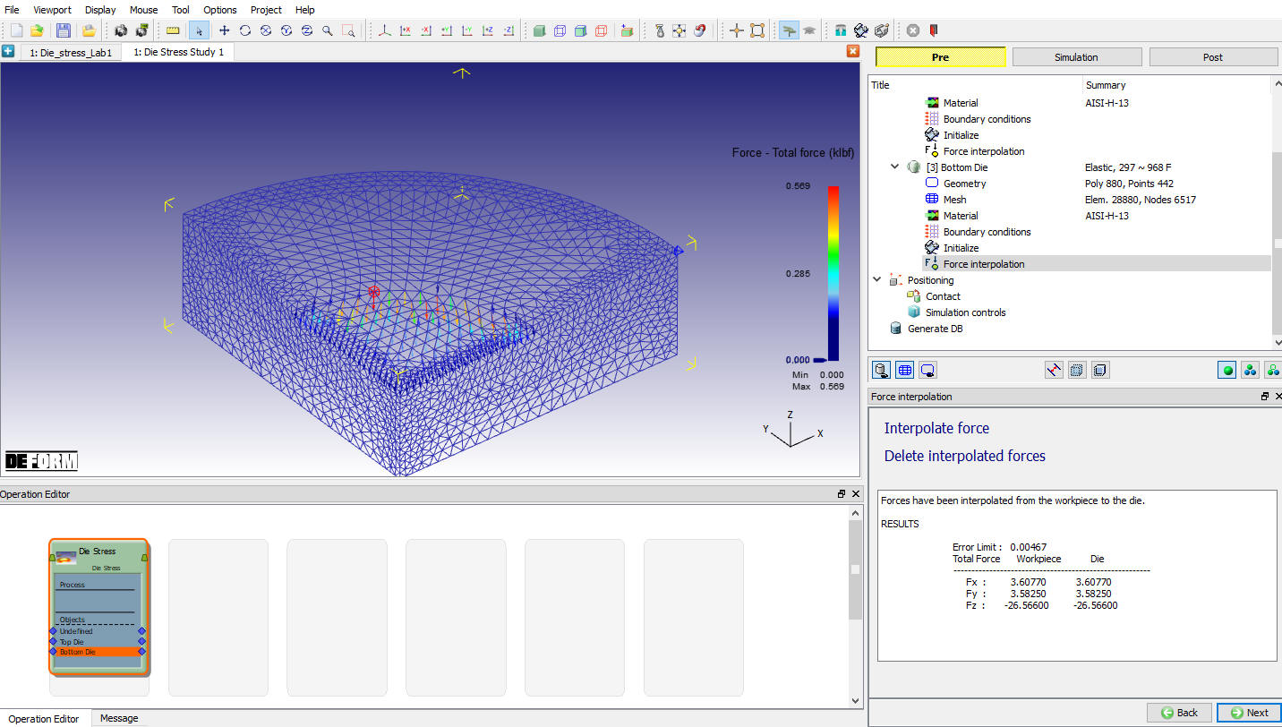
Force interpolation window
Click ![]() to enter the controls page. There is no need of Positioning in this case. So, click
to enter the controls page. There is no need of Positioning in this case. So, click ![]() to enter the Inter-Object Contact page. For this case there is no need of any Inter-Object Contact relations as there are no objects in contact.
to enter the Inter-Object Contact page. For this case there is no need of any Inter-Object Contact relations as there are no objects in contact.
Simulation Controls
By clicking ![]() we will enter into Simulation controls page. Keep number of simulation steps as 1 , step increment to save as 1 and Max. elapsed process time per step as 1. Keep the Conjugate - Gradient solver and click
we will enter into Simulation controls page. Keep number of simulation steps as 1 , step increment to save as 1 and Max. elapsed process time per step as 1. Keep the Conjugate - Gradient solver and click ![]() to enter the database generation page.
to enter the database generation page.
Generate Database
By selecting the File menu ![]() Export option, Save a keyword file for the problem as “Diestress “.
Export option, Save a keyword file for the problem as “Diestress “.
Click on ![]() action label to check the problem. Generate a database by clicking
action label to check the problem. Generate a database by clicking ![]() action label.
action label.
Click on the ![]() action label to open the Run Options dialog. Use the default Continue Run option to select “Continue from the last step ” option and then select the Simulation mode as Interactive. Click on
action label to open the Run Options dialog. Use the default Continue Run option to select “Continue from the last step ” option and then select the Simulation mode as Interactive. Click on ![]() button to run the simulation. As we click on
button to run the simulation. As we click on ![]() button, simulation starts.
button, simulation starts.
After completion of Simulation, switch to Post mode by selecting ![]() button.
button.
Post Processing
Using the State Variable ![]() menu, plot Effective stress and Max Principal stress as shown in Fig. 3DDSL1.16. and Fig. 3DDSL1.17.
menu, plot Effective stress and Max Principal stress as shown in Fig. 3DDSL1.16. and Fig. 3DDSL1.17.
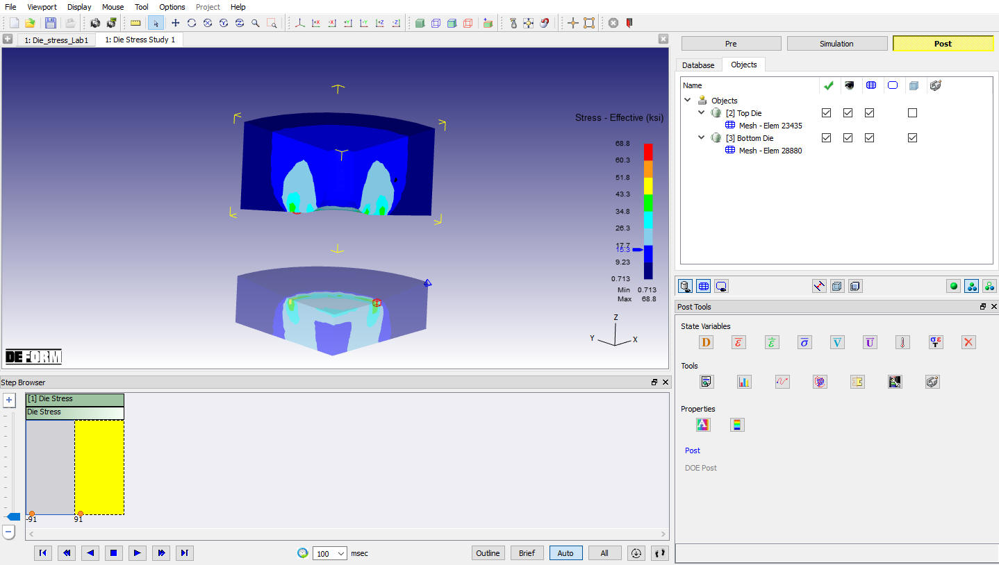
Stress effective plot

Max Principal stress
Related Topics:
2D Die Stress Analysis - Theory