Running creep simulations in DEFORM-2D
1.1. Introduction
1.2. Lab: 2D Creep Simulation setup
1.2.1. Creating New Problem
1.2.2. Adding 2D Operation
1.2.3. Geometry Type
1.2.4. Simulation Type
1.2.5. Load material
1.2.6. Adding Object
1.2.7 .Workpiece
1.2.8. Contact
1.2.9. Step Controls
1.2.10. Generate Database
1.2.11. Running Simulation
1.2.12. Post Processing
Introduction
Creep is slow, continuous deformation with respect to time. The strain instead of depending only on the stress is a function of temperature and time. To run creep/stress relaxation simulations in DEFORM®, the main issue is acquiring the material data. There are several common laws available for the creep modelling that can be seen in the material data section. If a specimen is under a constant tension and a given temperature, creep will give a changing strain over the total amount of time There are three different modes of creep: primary, secondary (steady-state), tertiary. The scale is not correct as the secondary creep generally has a much larger range of time compared to the other two modes. Secondary creep is the only mode that is modelled and fitting experimental data to a power law curve does this as below:
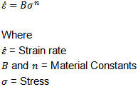
Many of the available forms are just fancier versions of this basic form (known as the power law curve). It is easy to fit data to this curve by plotting log-log curve and fit the curve to a linear slope to obtain both B and n (or whatever form is being used).
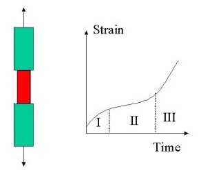
Typical Creep Curve example
Fig. 2DCRPL1.1. shows Strain versus Time response for a specimen under constant load at a given temperature exhibiting creep behavior. Note the three different regions of response in the strain-time curve, I -> Primary creep, II -> Secondary (Steady State) creep and III -> Tertiary creep.
To run a creep simulation, the following requirements must be fulfilled:
-
The workpiece should be made elasto-plastic
-
Creep (CREEP) has to be activated in the **Object Properties
 **Deformation tab
 -
A creep model with non-trivial data has been defined (any of the given model is sufficient). In the case of user routines, the required routine should have the routine compiled and the simulation should run the special FEM engine.
-
There is either a non-zero stress state on the part (relaxation case) or an applied traction to the body (creep).
-
Constrain the workpiece with velocity boundary conditions alone as the penalty method of contact can give some numerical error in the stress solution for creep cases
Lab: 2D Creep Simulation setup
1.2.1. Creating New Problem
1.2.2. Adding 2D Operation
1.2.3. Geometry Type
1.2.4. Simulation Type
1.2.5. Load material
1.2.6. Adding Object
1.2.7 .Workpiece
1.2.8. Contact
1.2.9. Step Controls
1.2.10. Generate Database
1.2.11. Running Simulation
1.2.12. Post Processing
Creating New Problem
On a Windows machine, go to the ![]() button select DEFORM-v1x.xxx (.xxx indicates version number E.g. v14.0.2) and select DEFORM GUI Main v1x.x from the menu. The DEFORM GUI Main window will appear.
button select DEFORM-v1x.xxx (.xxx indicates version number E.g. v14.0.2) and select DEFORM GUI Main v1x.x from the menu. The DEFORM GUI Main window will appear.
New Problem page
Create a new problem either by selecting File ![]() New Problem or by clicking the New Problem
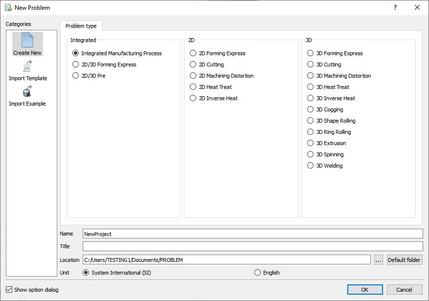
New Problem or by clicking the New Problem ![]() icon. The Problem Setup window will appear. Select “Integrated Manufacturing Process “ radio button and unit system as “SI “ as shown in Fig. 2DCRPL1.2.. Define Problem Name as “Creep “ and make sure the “Show option dialog” check box is turned on (if we do not turn on the “Show option dialog ” check box, then we will not get the New Project dialog in MO UI). Then click on
icon. The Problem Setup window will appear. Select “Integrated Manufacturing Process “ radio button and unit system as “SI “ as shown in Fig. 2DCRPL1.2.. Define Problem Name as “Creep “ and make sure the “Show option dialog” check box is turned on (if we do not turn on the “Show option dialog ” check box, then we will not get the New Project dialog in MO UI). Then click on ![]() button to open a new Problem using the Deform Integrated Manufacturing Process.
button to open a new Problem using the Deform Integrated Manufacturing Process.
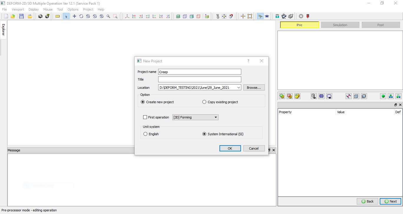
Multiple operation wizard will open with the New Project dialog at this point user will be prompted to specify a project name (system will create a separate folder with this project name) and title for this session. In this session we will use “Creep “ as the project name, see Fig. 2DCRPL1.3. Click on ![]() to continue, MO wizard will open.
to continue, MO wizard will open.
MO Wizard New Project Opening Window
Adding Forming operation
Multiple Operation wizard will open new project, add one 2D Forming operation from Explorer Operations list by clicking ![]() button as shown in Fig. 2DCRPL1.4.
button as shown in Fig. 2DCRPL1.4.
Added 2D Forming operation into Operation Editor
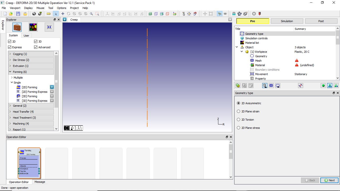
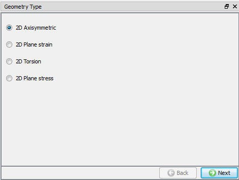
Geometry Type
In this lab we will be using Axisymmetric geometries, so select 2D Axisymmetric radio button from geometry type page as shown in Fig. 2DCRPL1.5., then click ![]() to simulation controls page.
to simulation controls page.
Axisymmetric Geometry type selection
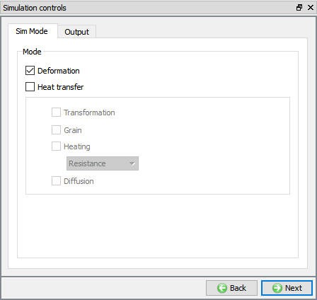
Simulation Controls
Current setup is isothermal, so in Simulation controls uncheck the Heat transfer mode check box (See Fig. 2DCRPL1.6.) and click ![]() to material page.
to material page.
Simulation control window
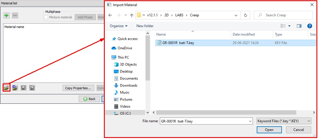
Loading Material
Click on Material list from Operation tree, material list window will be opened. Load the material from file GR-0001R tset-T.Key file available under /2D/LABS/Creep folder as shown in Fig. 2DCRPL1.7., then click ![]() to object page.
to object page.
Loading Material
Adding Objects
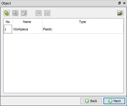
For this operation we require only one object, hence retain Workpiece and delete the other two objects by clicking the ![]() button. (See Fig. 2DCRPL1.8.) Click
button. (See Fig. 2DCRPL1.8.) Click ![]() to workpiece page.
to workpiece page.
Adding Object Window
Workpiece
In Workpiece Object page, retain default name and change Object type to Elasto-Plastic. Object type must be Elasto-plastic in order to enable to creep calculations. Define object temperature as 650 °C (see Fig. 2DCRPL1.9.). Click ![]() to Geometry page.
to Geometry page.
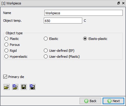
Workpiece General page
Workpiece Geometry
Click on ![]() , select Cylinder and define Radius as 50 , Height as 40 as shown in Fig. 2DCRPL1.10. Click on
, select Cylinder and define Radius as 50 , Height as 40 as shown in Fig. 2DCRPL1.10. Click on ![]() button to accept all the changes and go back to the Geometry definition. 2D geometry is created, click on
button to accept all the changes and go back to the Geometry definition. 2D geometry is created, click on ![]() to Mesh page.
to Mesh page.
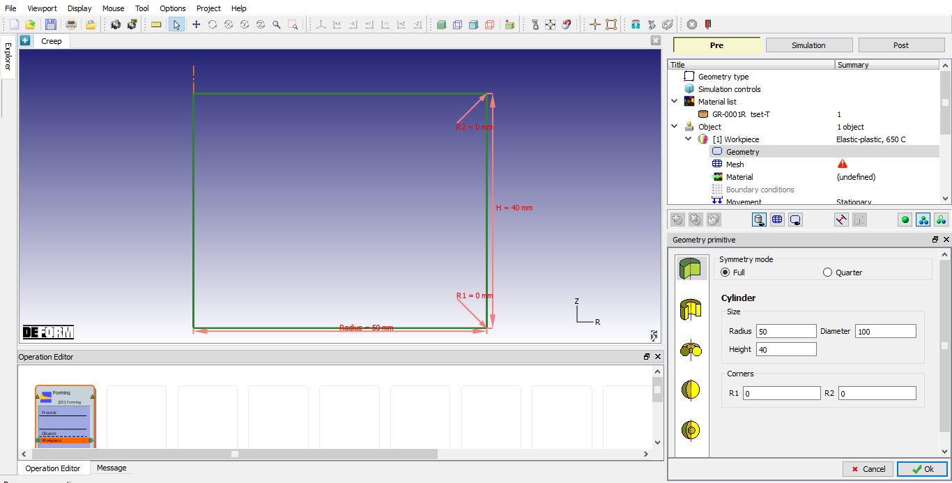
Workpiece Geometry
Generating mesh for Workpiece
To generate a mesh, click on ![]() icon to switch to expert mode. Define T**a rget number of elements** as 500 , Thickness elements as 5 and Size ratio as 1 as shown in Fig. 2DCRPL1.11. Click on the
icon to switch to expert mode. Define T**a rget number of elements** as 500 , Thickness elements as 5 and Size ratio as 1 as shown in Fig. 2DCRPL1.11. Click on the ![]() button to generate the mesh. Click on
button to generate the mesh. Click on ![]() to Material page.
to Material page.
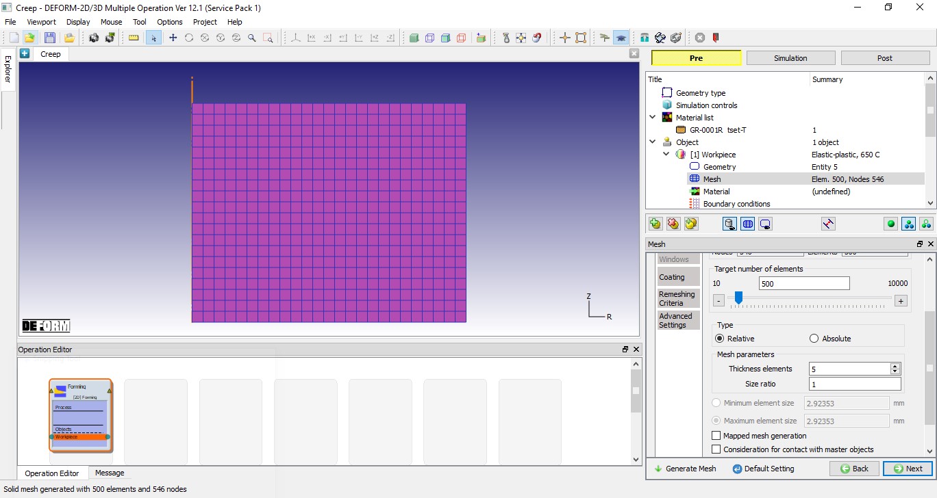
Expert mode mesh page
Assign Material to Workpiece
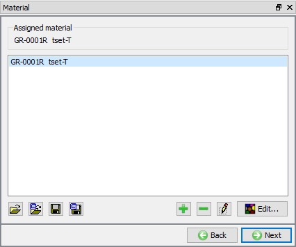
Select the GR-0001R tset-T from material window to assign the material to the Workpiece as shown in Fig. 2DCRPL1.12. Click on ![]() to BCC page.
to BCC page.
Assign Material to Workpiece
Assign BCC to Workpiece
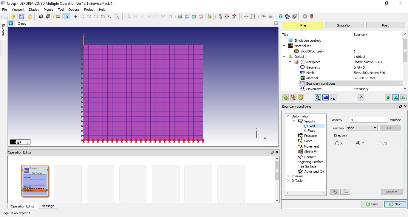
In BCC page, verify Velocity BCC under Deformation, nodes along the axis must be constrained in X-direction. If the BCC’s are not assigned, assign them manually and we should also define Velocity BCC with 0 velocity on bottom side of the workpiece in Y-Direction to constrain workpiece along Y direction as shown in below Fig. 2DCRPL1.13. Define Pressure BCC with 200 MPa on Top surface of the workpiece as shown in below Fig. 2DCRPL1.14. Click on ![]() to Properties page.
to Properties page.
Assign Velocity BCC to Workpiece
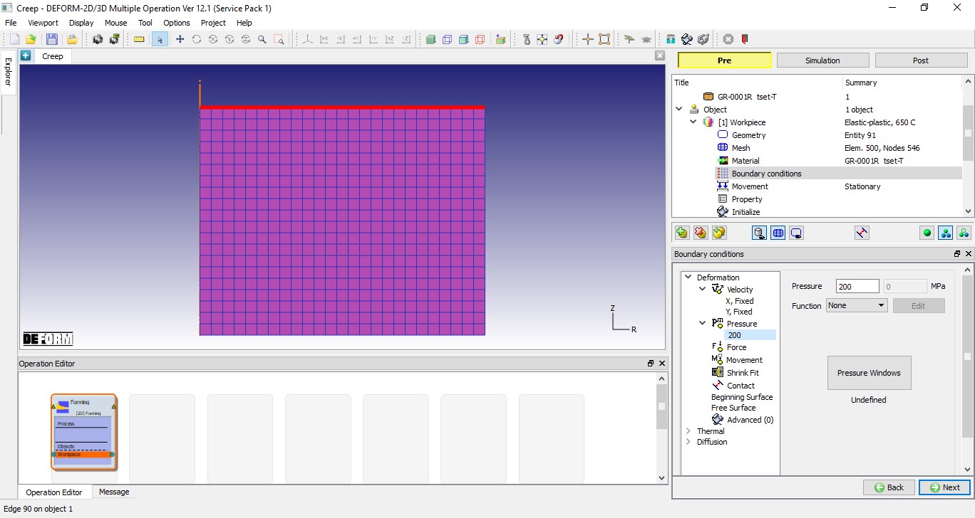
Assign Pressure BCC to Workpiece
Turning on Creep calculations
In properties page, Creep calculation options will be enabled for Elasto-plastic object type. Select “Always activ e” radio button under Creep calculation tab to enable creep calculations, see Fig. 2DCRPL1.15.
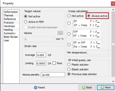
Turning on Creep calculations in object properties page
Contact Generation
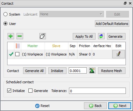
In this lab we have only one object, hence we will define self-contact by specifying Workpiece as Master and Slave as shown in Fig. 2DCRPL1.16. click on ![]() until Step page.
until Step page.
Contact Generation page
Step Controls
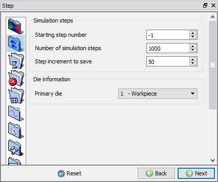
In step controls page, select ![]() , define Number of Simulation steps as 1000 and Step Increment to save as 50 as shown in Fig. 2DCRPL1.17.
, define Number of Simulation steps as 1000 and Step Increment to save as 50 as shown in Fig. 2DCRPL1.17.
Simulation Steps - Simulation controls
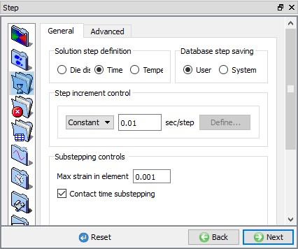
Select ![]() step definition tab, select Time as Solution step definition type and define Constant 0.01 sec under Step increment control. Define Max strain value as 0.001 as shown in Fig. 2DCRPL1.18.
step definition tab, select Time as Solution step definition type and define Constant 0.01 sec under Step increment control. Define Max strain value as 0.001 as shown in Fig. 2DCRPL1.18.
Step Increment - Simulation controls
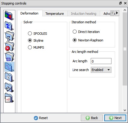
Select ![]() solvers tab, in Deformation tab select “Newton-Raphson “ as Iteration method and “Skyline “ as the solver as shown in the Fig. 2DCRPL1.19.
solvers tab, in Deformation tab select “Newton-Raphson “ as Iteration method and “Skyline “ as the solver as shown in the Fig. 2DCRPL1.19.
Solver settings - Simulation controls
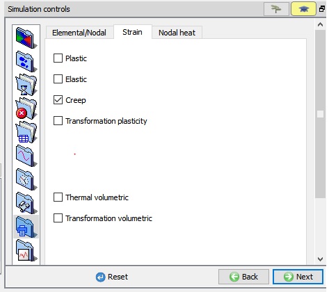
Select ![]() Output controls tab and click on Strain tab, turn on Creep check box as shown in Fig. 2DCRPL1.20. to view strain due to creep. Click on
Output controls tab and click on Strain tab, turn on Creep check box as shown in Fig. 2DCRPL1.20. to view strain due to creep. Click on ![]() button to Generate DB page.
button to Generate DB page.
Advanced options page
Generate Database
In Generate DB page, click the ![]() button to have the program check to see if anything was missed in the problem setup. During the checking process, messages in the red color signify data that needs to be fixed before a simulation can be run (such as when you forget to define any material data).
button to have the program check to see if anything was missed in the problem setup. During the checking process, messages in the red color signify data that needs to be fixed before a simulation can be run (such as when you forget to define any material data).
Click on ![]() button to generate the database.
button to generate the database.
Running Simulation
Once the database has been generated, switch to the Simulation mode by clicking on ![]() button above the operation tree. Click on the
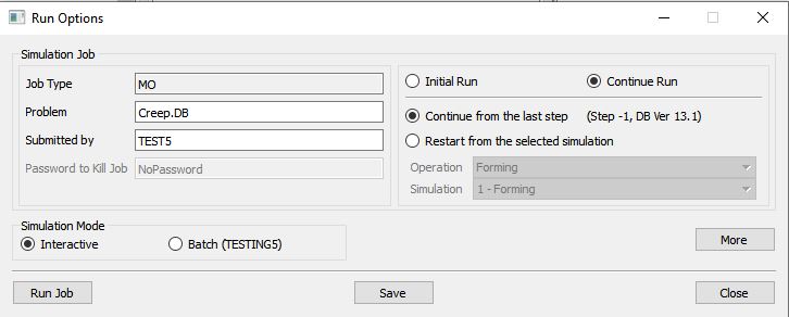
button above the operation tree. Click on the ![]() action label to open the Run Options dialog as shown in Fig. 2DCRPL1.21. Use the default Continue Run option to select “Continue from the last step ” (from step -1) option and then select the Simulation mode as Interactive and click on
action label to open the Run Options dialog as shown in Fig. 2DCRPL1.21. Use the default Continue Run option to select “Continue from the last step ” (from step -1) option and then select the Simulation mode as Interactive and click on ![]() button to run the simulation.
button to run the simulation.
Run Simulation window
The progress of the simulation can be monitored as it simulates by looking at the Simulation Message tab and Simulation Graphics from the Graphics display region in Simulation mode. if the ![]() option is checked in Simulation Message tab, which is the default setting, the Message file will refresh automatically.
option is checked in Simulation Message tab, which is the default setting, the Message file will refresh automatically.
The Message file provides information about which simulation step the simulation is currently on and information dealing with how well the simulation is running.
Post Processing
When the simulation is completed, review the results by switching to Post mode using the ![]() button above the Simulation tool bar. Go to last step of simulation and Plot Creep strain from state variable list and observe the Creep strain distribution over workpiece in display area as shown in Fig. 2DCRPL1.22.
button above the Simulation tool bar. Go to last step of simulation and Plot Creep strain from state variable list and observe the Creep strain distribution over workpiece in display area as shown in Fig. 2DCRPL1.22.
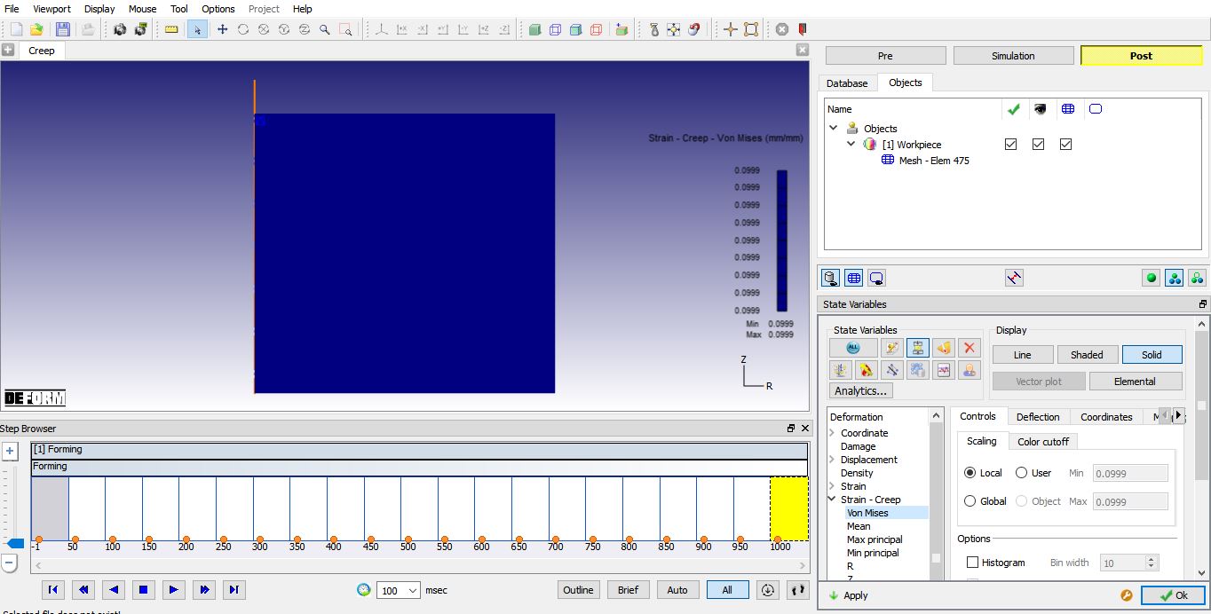
Strain creep distribution at the last step