3D Heat Transfer operation Lab
This lab will demonstrate how to setup a typical multiple operation simulation involving different heat transfer and forging operations. During this lab we will also attempt to highlight various features of the system that user can include in other type of multiple operation situations. These operations can be a set of heat resting operation (see Fig. 3DHTRL1.1.), a set of deformation operations with changing dies between operations, or a combination of both heat transfer and deformation operations (see Fig. 3DHTRL1.1.). The 3D model explained in this lab is full model and the following 3D images are used for illustration purpose only.
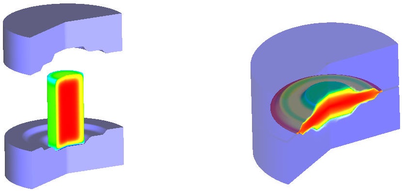
3D illustration of Heat Resting and Forming operations
In this lab, we setup a four operations model involving one ‘Heat Furnace’, ‘Heat Transfer’, ‘Heat Resting’ one ‘Deformation’ and Heat Dwelling operations. The part is cylindrical workpiece, which first undergoes a furnace heating operation for one hour at 2000 F, followed by a heat transfer operation for 15 seconds during the transfer from the furnace to the forming station. This operation will be followed by a heat resting operation where the workpiece rests on forming dies for 4 seconds prior to a deformation operation. Deformation operation runs for a specific stroke of (7.25”) the upper die. Finally Dwelling operation for 4 seconds. The entire sequence can be setup using this system and all the operations can be simulated without user intervention in batch mode.
1.1. Creating New Problem and Adding Operations
1.2. Operation1: Furnace Heating Setup
1.3. Operation2: Air Transfer
1.4. Operation3: Heat Resting
1.5. Operation4: Forming
1.6. Operation5: Heat Dwelling
1.7. Simulate problem
1.8. Post Processing
Creating New Problem and Adding Operations
Creating New Problem
On a Windows machine , go to the ![]() button select DEFORM-v1x.xxx (.xxx indicates version number E.g. v14.0.2.) and select DEFORM GUI Main vxx.xx from the menu. The DEFORM GUI Main window will appear.
button select DEFORM-v1x.xxx (.xxx indicates version number E.g. v14.0.2.) and select DEFORM GUI Main vxx.xx from the menu. The DEFORM GUI Main window will appear.
Create a new problem either by selecting File ![]() New Problem or by clicking the New Problem
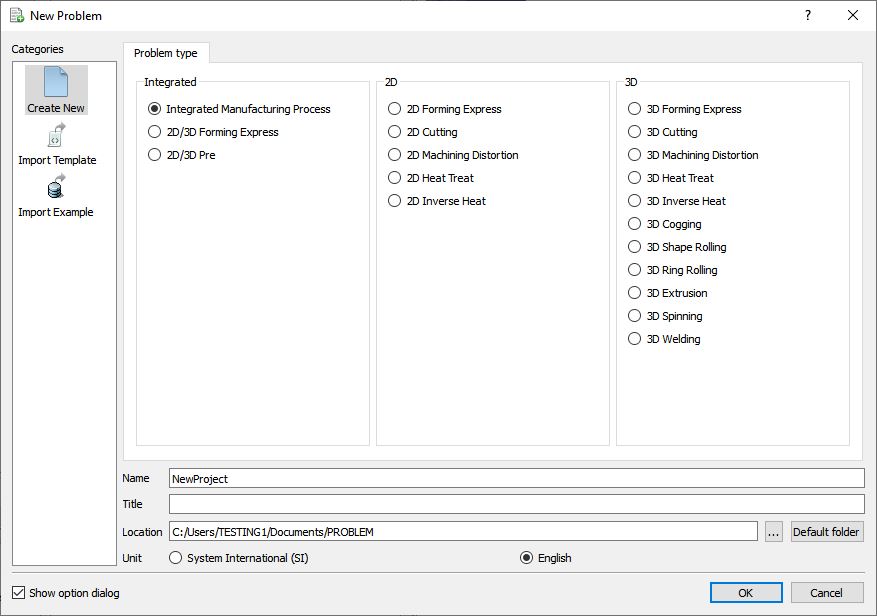
New Problem or by clicking the New Problem ![]() icon. The Problem Setup window will appear as shown in Fig. 3DHTRL1.2. Select “Integrated Manufacturing Process “ radio button and unit system as “English “ radio button in unit field. Define Problem Name as “ 3D_Heat_Transfer_Operations “ and make sure the “Show option dialog” check box is turned on (if we do not turn on the “Show option dialog ” check box, then we will not get the New Project dialog in MO UI). Then click on
icon. The Problem Setup window will appear as shown in Fig. 3DHTRL1.2. Select “Integrated Manufacturing Process “ radio button and unit system as “English “ radio button in unit field. Define Problem Name as “ 3D_Heat_Transfer_Operations “ and make sure the “Show option dialog” check box is turned on (if we do not turn on the “Show option dialog ” check box, then we will not get the New Project dialog in MO UI). Then click on ![]() button to open a new Problem using the Deform Integrated Manufacturing Process.
button to open a new Problem using the Deform Integrated Manufacturing Process.
New Problem window
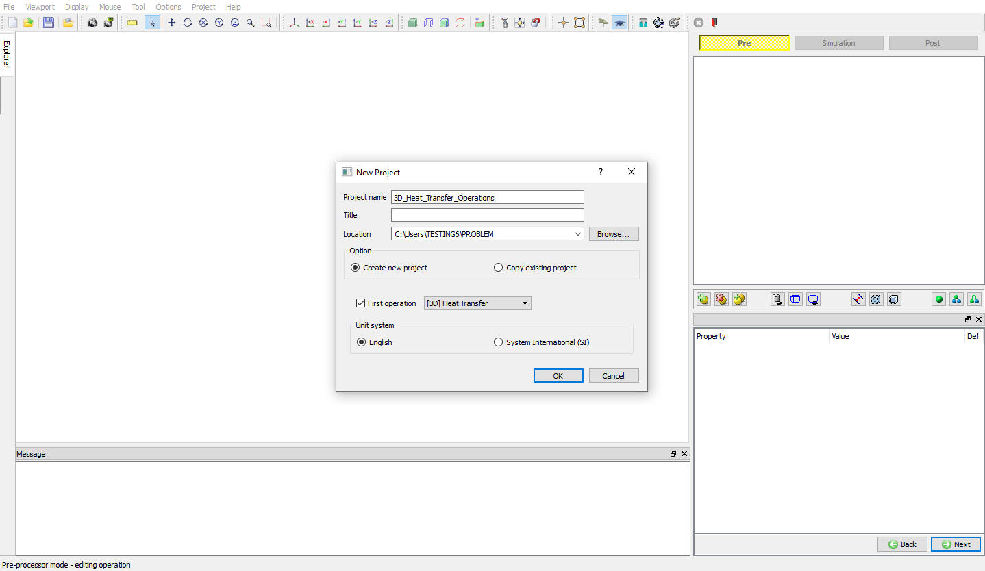
Multiple operation wizard will open with the New Project dialog as shown in Fig. 3DHTRL1.3., at this point user will be prompted to specify a project name (system will create a separate folder with this project name) and title for this session. In this session we use ‘3D_Heat_Transfer_Operations ’ as the project name. Select the first operation as 3D Heat transfer operation and check the checkbox to add Heat transfer operation as first operation. Click on ![]() to continue to open the operation.
to continue to open the operation.
MO Wizard New Project Opening Window
Adding other operations
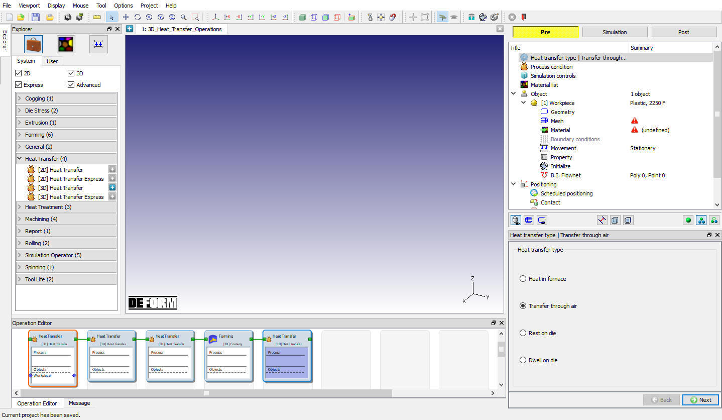
Multiple Operation wizard will opens new project with one 3d Heat transfer operation. Addtwo more heat transfer operations for Air transfer and Resting, one Forming operation and heat transfer operation for Dwelling after forming from Explorer Operations list by clicking ![]() button as shown in Fig. 3DHTRL1.4.
button as shown in Fig. 3DHTRL1.4.
Adding Operations
Operation1: Furnace Heating Setup
For first heat transfer operation change the operation name as “Furnace Heating “ by double clicking on Operation name in Operation Editor window as shown in Fig. 3DHTRL1.5. and press Enter in Keyboard.
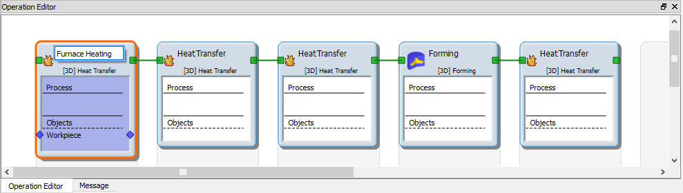
Name the first operation as Furnace Heating
Select Heat Transfer Type for Furnace Heating
Select Heat in Furnace heat transfer type for Furnace heating operation as shown in Fig. 3DHTRL1.6. This will set the default heat transfer settings for heating operation. Click ![]() to continue.
to continue.
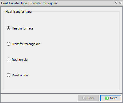
Heat transfer type selection for Furnace Heating
Set Process Conditions for Furnace Heating
Define Heating time as 3600 sec (one hour of heating) at 2000F furnace temperature or environment temperature as shown in Fig. 3DHTRL1.7. and click on ![]() to continue.
to continue.
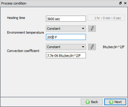
Process Condition settings for Furnace Heating
Select Simulation Controls for Furnace Heating
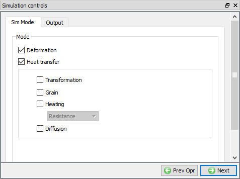
Keep only HeatTransfer mode checked as only heat transfer is modeling as shown in Fig. 3DHTRL1.8. and click ![]() to continue.
to continue.
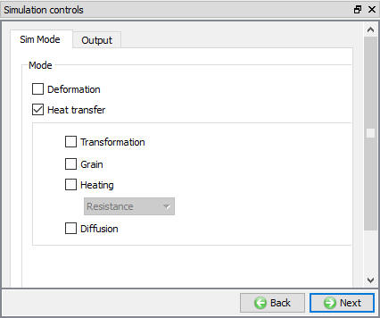
Simulation Controls settings for Furnace Heating
Import Workpiece Material
In Material window, load the material AISI-8620 from DEFORM Material library, from Steel category using ![]() (Load material data from library) option. This can be done as shown in Fig. 3DHTRL1.9. by clicking
(Load material data from library) option. This can be done as shown in Fig. 3DHTRL1.9. by clicking ![]() button. Material can also be loaded from Materials list in Explorer.
button. Material can also be loaded from Materials list in Explorer.
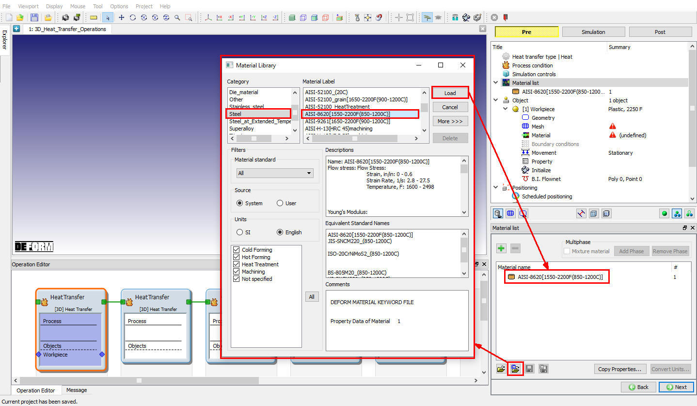
Importing Workpiece material from DEFORM library
Check Material properties
Click ![]() to check the thermal material properties. Select Thermal tab (see Fig. 3DHTRL1.10.) and click on
to check the thermal material properties. Select Thermal tab (see Fig. 3DHTRL1.10.) and click on ![]() (Define) button next to Thermal Conductivity to observe the Thermal conductivity function of temperature as shown in Fig. 3DHTRL1.11.
(Define) button next to Thermal Conductivity to observe the Thermal conductivity function of temperature as shown in Fig. 3DHTRL1.11.
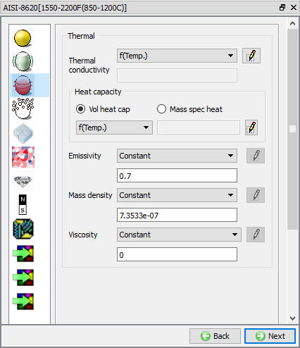
Material property definition window for AISI-8620
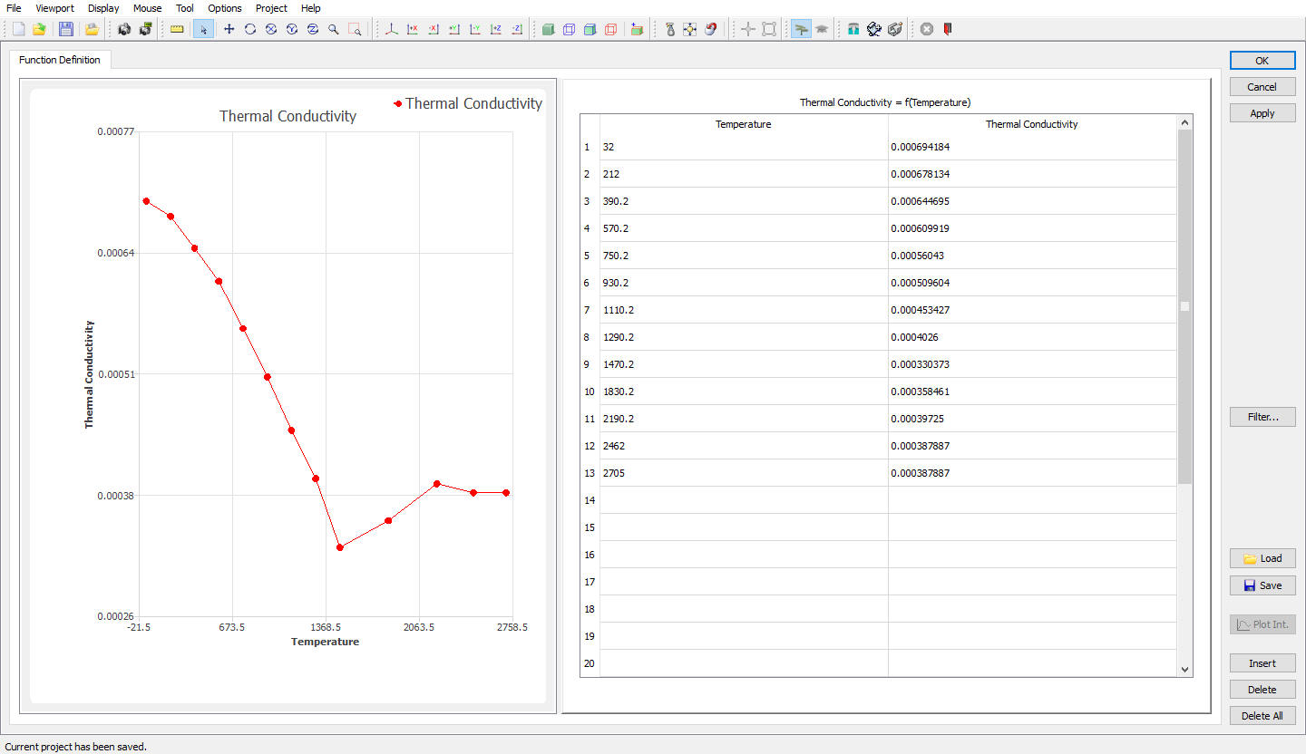
Thermal Conductivity function of temperature data for AISI-8620
Similarly click on ![]() (Define) button next to Heat capacity and observe the function data as shown Fig. 3DHTRL1.12.
(Define) button next to Heat capacity and observe the function data as shown Fig. 3DHTRL1.12.

Heat capacity function of temperature data for AISI-8620
For Emissivity and Mass density constant value is defined as shown in Fig. 3DHTRL1.10. Then click ![]() for Material properties and Object window, as only Workpiece object is enough for heating furnace operation.
for Material properties and Object window, as only Workpiece object is enough for heating furnace operation.
Define Workpiece
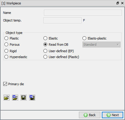
In Workpiece object window, keep the object type as ‘Plastic ’ (see Fig. 3DHTRL1.13.). At this stage user can also specify initial temperature of the workpiece as 68 °F. Click on ![]() to continue and import the workpiece geometry.
to continue and import the workpiece geometry.
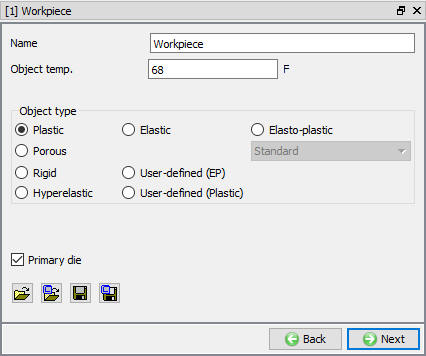
Workpiece Object definition
2D to 3D Geometry conversion for Workpiece
In this lab 3D geometry is created by revolving the 2d geometry, so check “Use cross section” checkbox to convert the 2D geometry into 3D geometry as shown in Fig. 3DHTRL1.14.
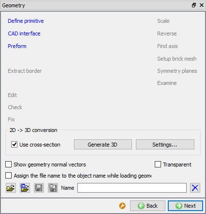
2D to 3D geometry conversion selection in 3d geometry window
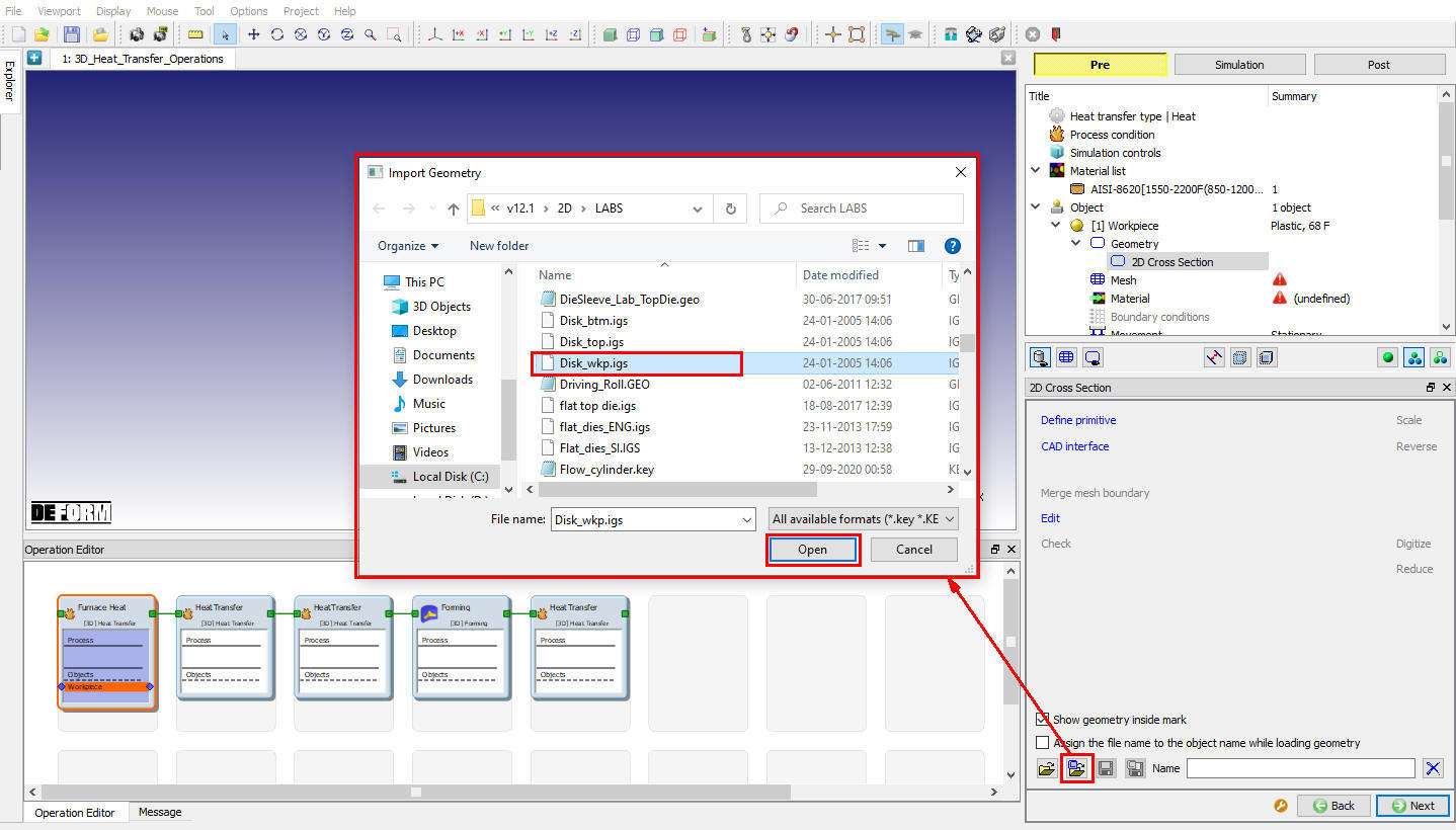
Click on ![]() and in 2d geometry window, click on
and in 2d geometry window, click on ![]() (Load geometry from library) button to load the Disk_wkp.igs 2d geometry file from DEFORM installation location 2D\LABS\ as shown in Fig. 3DHTRL1.15. Click
(Load geometry from library) button to load the Disk_wkp.igs 2d geometry file from DEFORM installation location 2D\LABS\ as shown in Fig. 3DHTRL1.15. Click ![]() If System ask the 2D\LABS\ location to be saved as library location.
If System ask the 2D\LABS\ location to be saved as library location.
2d geometry importing from DEFORM 2d geometry library for workpiece
Other options available at this stage are, defining the workpiece from the Primitive geometry and importing 3d geometry using “Define Primitive” and import 3d geometry options.
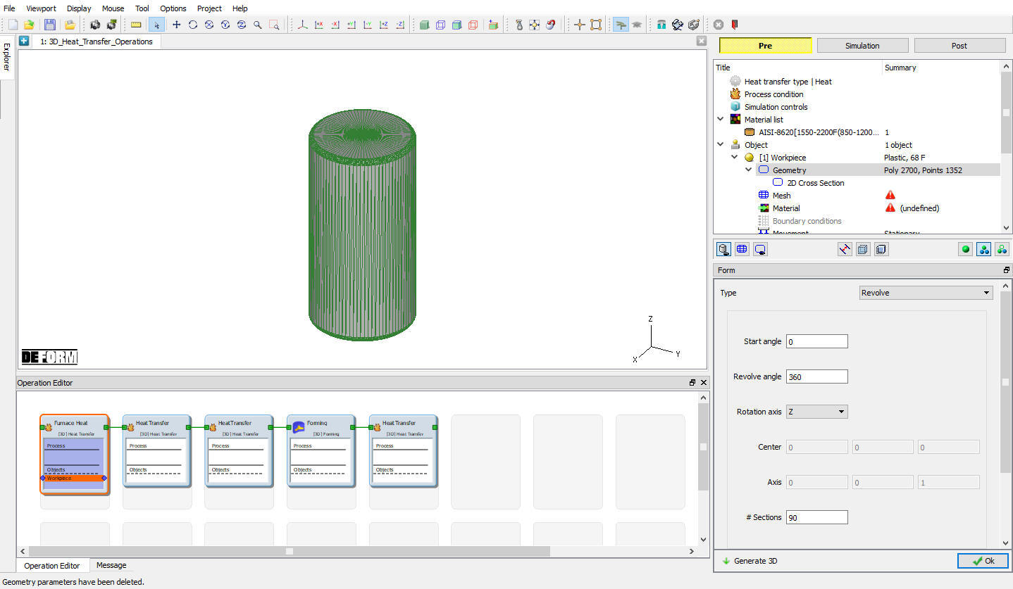
After importing the 2D geometry, click on ![]() and click on **2D- >3D Conversion **
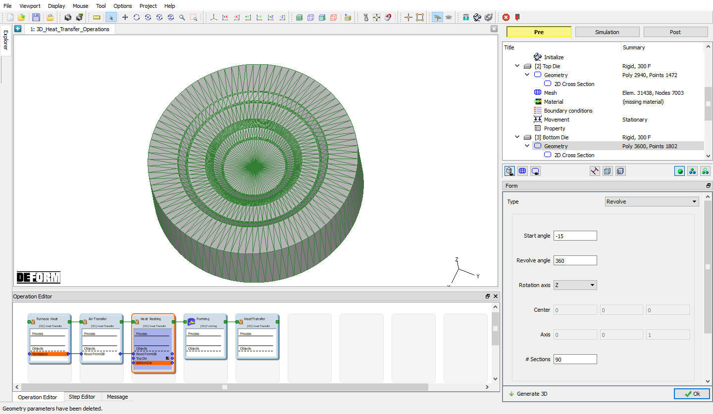
and click on **2D- >3D Conversion **![]() button. In settings window select the conversion type as Revolve and make sure the revolve angle is 360° and rotation axis is Z, keep the other defaults (see Fig. 3DHTRL1.16.) and click on
button. In settings window select the conversion type as Revolve and make sure the revolve angle is 360° and rotation axis is Z, keep the other defaults (see Fig. 3DHTRL1.16.) and click on ![]() . Click on
. Click on ![]() to close the Conversion settings window.
to close the Conversion settings window.
Import geometry from DEFORM library
If any 3D geometry is imported for object then use ![]() action label to check the Geometry, a perfect geometry must have only one surface and no free edges and invalid polygon edges and orientations. If the geometry is not perfect then click on
action label to check the Geometry, a perfect geometry must have only one surface and no free edges and invalid polygon edges and orientations. If the geometry is not perfect then click on ![]() geometry option to fix these issues. Click on
geometry option to fix these issues. Click on ![]() until Mesh window.
until Mesh window.
Generate Workpiece Mesh
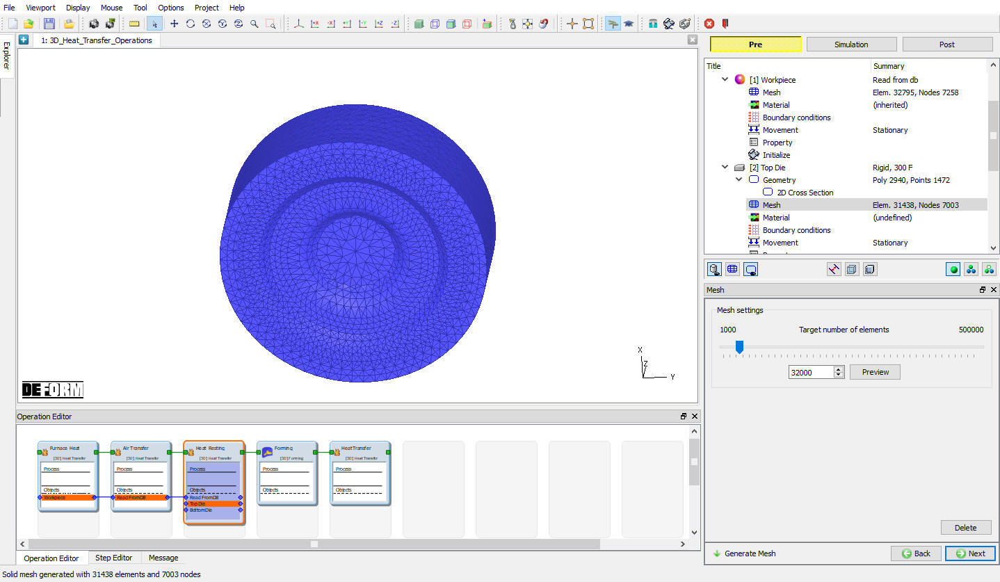
Generate the mesh using default 32000 elements (see Fig. 3DHTRL1.17.). Complete range of meshing options are also available in expert mode (![]() ), if user needs to have more control on the mesh generated. Click on
), if user needs to have more control on the mesh generated. Click on ![]() to continue.
to continue.
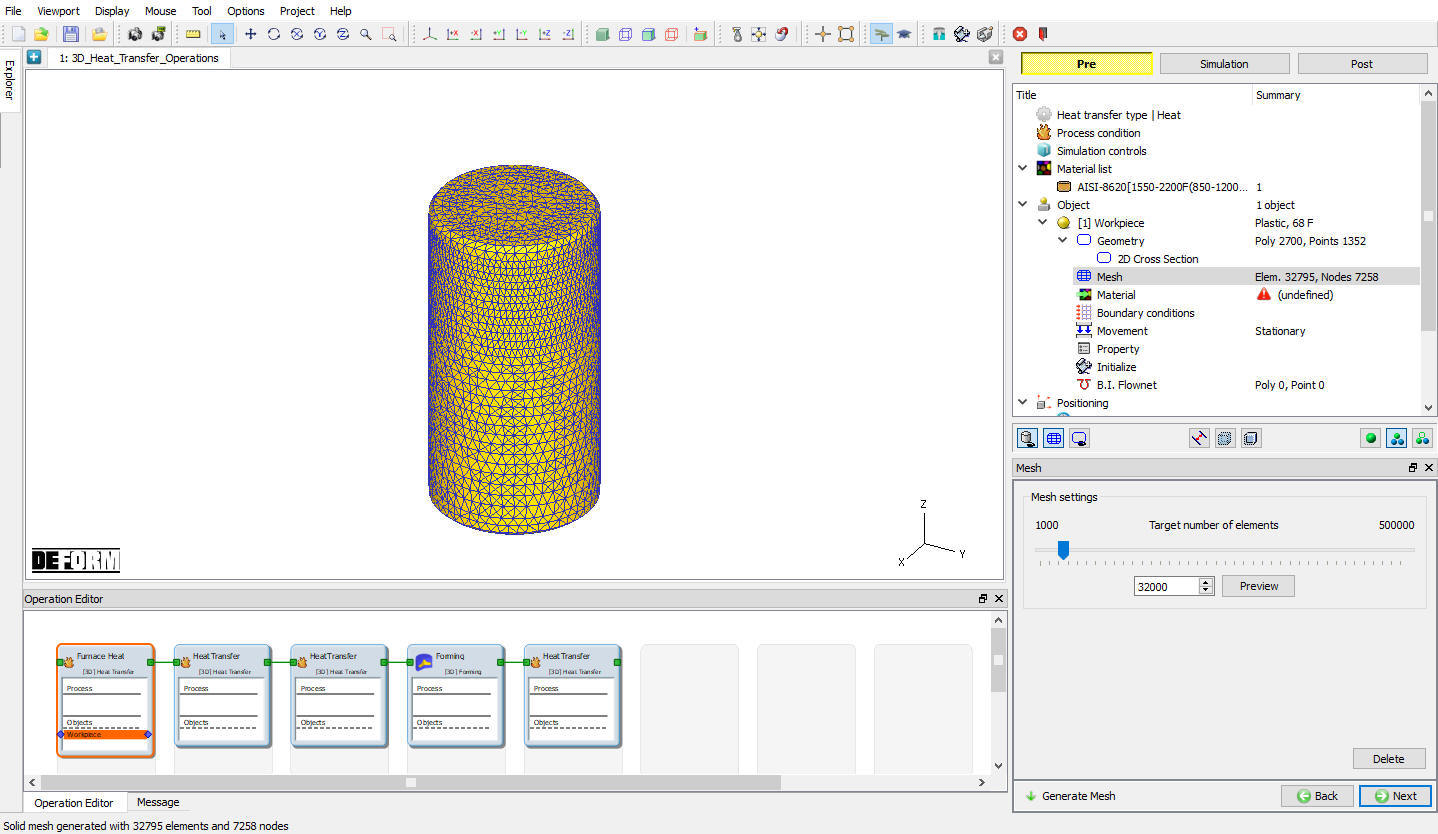
Mesh generation window
Assign Workpiece Material
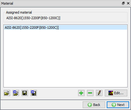
To assign material for workpiece select the material ‘AISI-8620 ’ from material window. This can be done as shown in Fig. 3DHTRL1.18. Click on ![]() to continue.
to continue.
Object material selection window
Defining Workpiece Boundary Conditions
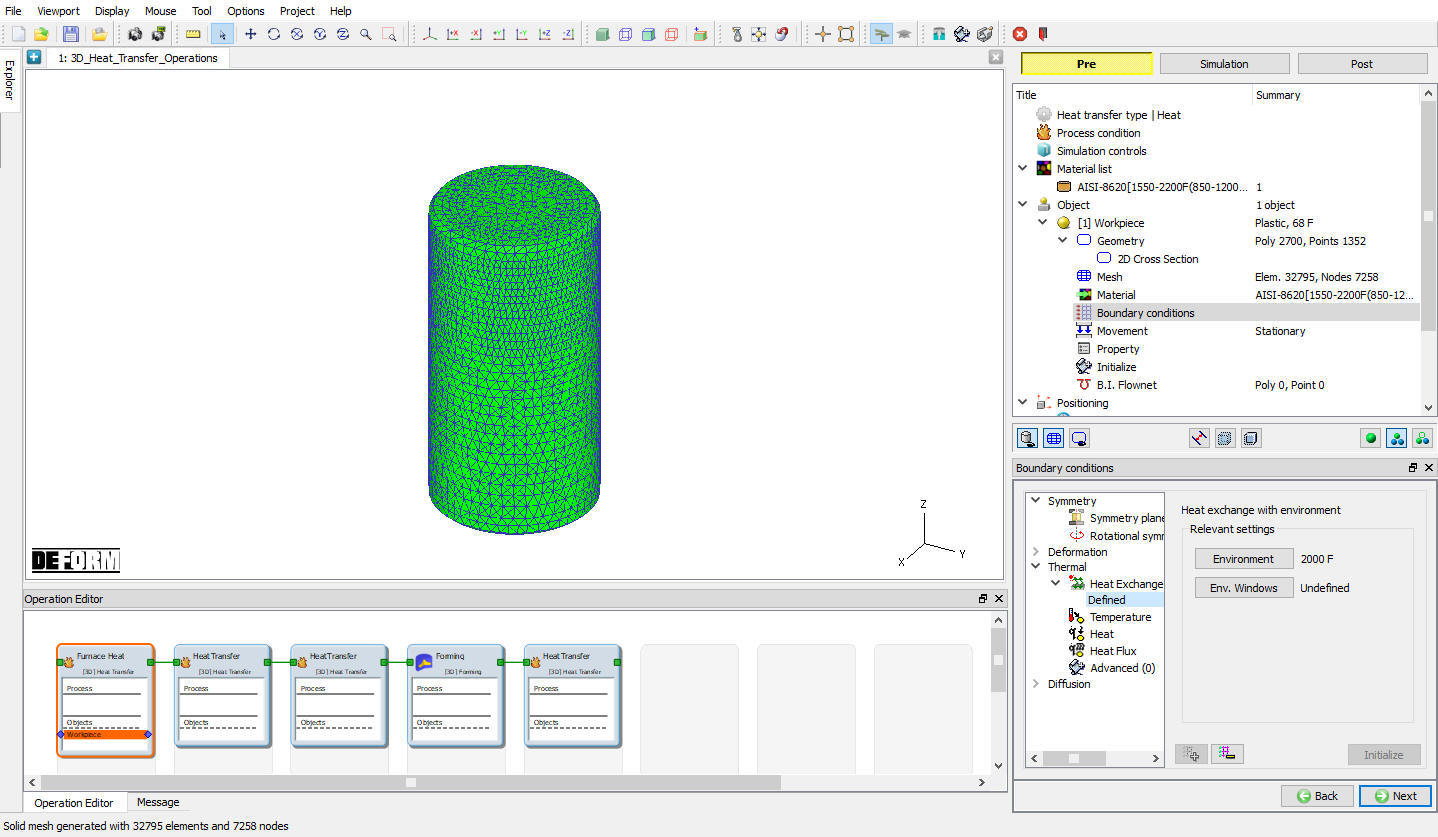
In BCC page, check the default assigned Heat exchange with Environment BCC to the entire outer surface of the Billet by clicking on Defined under Heat exchange with Environment. Default BCC are assigned automatically. (See Fig. 3DHTRL1.19.)
Boundary condition window
Click ![]() until Step controls window as there is no object positioning and thermal stopping controls definition is required.
until Step controls window as there is no object positioning and thermal stopping controls definition is required.
Define Step Controls for Furnace Heating
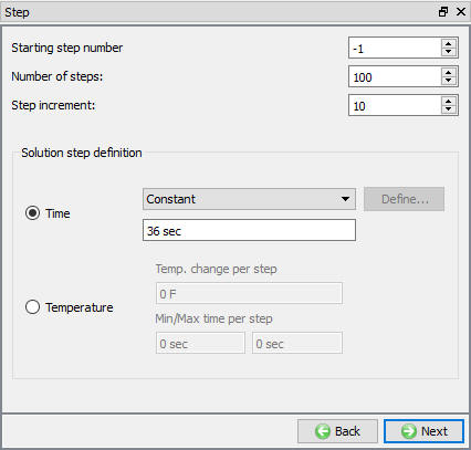
Set the number of simulation steps as 100 at 36 sec each and saving every10 steps (see Fig. 3DHTRL1.20.). Advanced Simulation controls settings are available in expert mode (![]() ). Click
). Click ![]() to proceed to the database generation stage.
to proceed to the database generation stage.
Simulation controls settings for Furnace Heating
Generate Database
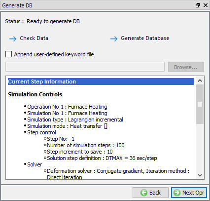
In database generation page, user can check the data required for the analysis and proceed to generate the database (see Fig. 3DHTRL1.21.). In First operation of any multiple operations, user is required to generate the database. For all the subsequent operations we only need to setup the process data and simulation controls. At this stage user also has an option of importing a keyword file, which is particularly useful for the later operations. Functionality of this ‘Append user defined keyword file’ feature will be discussed in the later sections of this lab. Click on ![]() to proceed to the next operation of ‘Air Transfer’.
to proceed to the next operation of ‘Air Transfer’.
Database Generation window for first operation
Operation2: Air Transfer
In this operation, we setup a heat transfer operation (air stage of the operation) involving transferring of a part for 15 sec from furnace to the forming station. During this time the part which is at about 2000F undergoes some cooling in ambient air.
Select Heat Transfer Type for Air Transfer
Name the operation as “Air Transfer “ by double clicking on Operation name in Operation Editor and press Enter from Keyboard to close. Select ‘Transfer through air ‘ heat transfer type as shown in Fig. 3DHTRL1.22. and click on ![]() to continue.
to continue.

Heat Transfer type selection for Air Transfer
Set Process Conditions for Air Transfer
Define the process conditions as transfer time of 15 sec in a 68 F environment using the default convection coefficient as shown in Fig. 3DHTRL1.23.

Process condition settings for Air Transfer
Click ![]() until Workpiece object window and accept object type as ‘Read from DB’ (see Fig. 3DHTRL1.24.). This indicates that workpiece object data from furnace heating operation will be available as a starting data for this operation. Click on Step controls branch in operation tree.
until Workpiece object window and accept object type as ‘Read from DB’ (see Fig. 3DHTRL1.24.). This indicates that workpiece object data from furnace heating operation will be available as a starting data for this operation. Click on Step controls branch in operation tree.
Read from DB object selection for workpiece
Set Step definition for Air Transfer
In Step Controls window define 15steps at1 sec increment and saving at every 5 steps (see Fig. 3DHTRL1.25.). Click on ![]() to continue.
to continue.
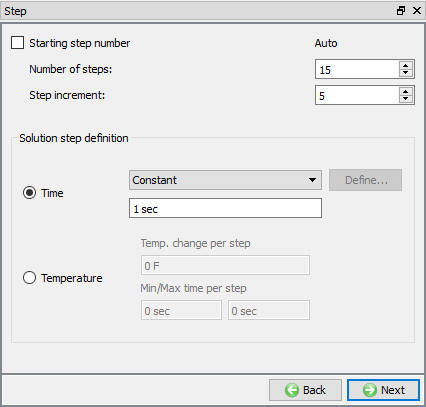
Step controls settings for air transfer operation
Click on ![]() to open the Heat resting operation, as database will generate for subsequent operations during simulation in batch mode (see Fig. 3DHTRL1.26.).
to open the Heat resting operation, as database will generate for subsequent operations during simulation in batch mode (see Fig. 3DHTRL1.26.).
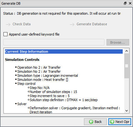
Database generation window for subsequent operations in batch mode
Note:
At this stage user has an option to bring in additional object or simulation data by opting to ‘Append user defined keyword file’ (See Fig.HTransL1.26.). Please not that, this keyword when defined will be read in by the system before the DB generation of the second operation. However no checking of the user defined data from this keyword file will be done at this stage.
Operation3: Heat Resting
In this operation we setup a heat resting operation, where the workpiece rests on forming dies for 4 seconds prior to a deformation operation.
Select Heat Transfer Type for Heat Resting
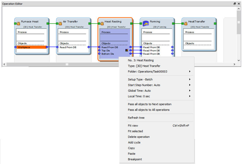
Name the operation as “Heat Resting “ by double clicking on Operation name in Operation Editor and press Enter from Keyboard to close. Select ‘Rest on die ‘ heat transfer type as shown in Fig. 3DHTRL1.27. and click on ![]() to continue.
to continue.
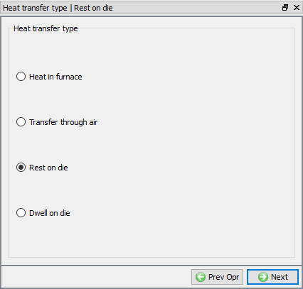
Heat transfer type selection for heat resting operation
Set Process Condition for Heat Resting
Set process condition as restingtime of 4 sec in a 68F environment using the default convection coefficient as shown in Fig. 3DHTRL1.28. click on ![]() .
.
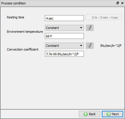
Process condition settings for Heat Resting operation
Add Die Objects
Click ![]() until Object window and accept the default Number of Objects 3.
until Object window and accept the default Number of Objects 3.
Define Top Die
Click on Top Die in operation tree. Accept the Top Die temperature 300 °F and object type as Rigid as shown in Fig. 3DHTRL1.29. Click ![]() to continue.
to continue.
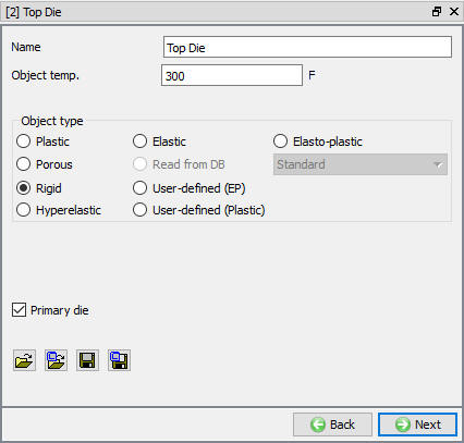
Top die object definition window for heat resting operation
2D to 3D Geometry Conversion for Top Die
Similar to workpiece geometry creation, convert the 2d geometry for Top die. So, Turn on “Use cross section “ checkbox (see Fig. 3DHTRL1.14.) and click ![]() to go to 2D geometry window, using
to go to 2D geometry window, using ![]() (Load Geometry from Library) button import ‘Disk_top.igs’ from installation path /2D/LABS/ as shown in Fig. 3DHTRL1.30.
(Load Geometry from Library) button import ‘Disk_top.igs’ from installation path /2D/LABS/ as shown in Fig. 3DHTRL1.30.
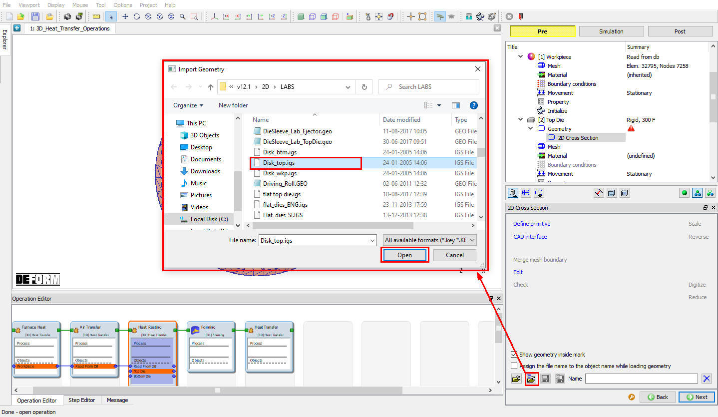
Importing the top die geometry from DEFORM geometry Library
After importing 2D geometry, click on ![]() and click on 2D- >3D Conversion
and click on 2D- >3D Conversion ![]() option, revolve the 2d geometry about 360°along Z axis as shown in Fig. 3DHTRL1.31. Click on
option, revolve the 2d geometry about 360°along Z axis as shown in Fig. 3DHTRL1.31. Click on ![]() button and click on
button and click on ![]() to close the Conversion settings window.
to close the Conversion settings window.
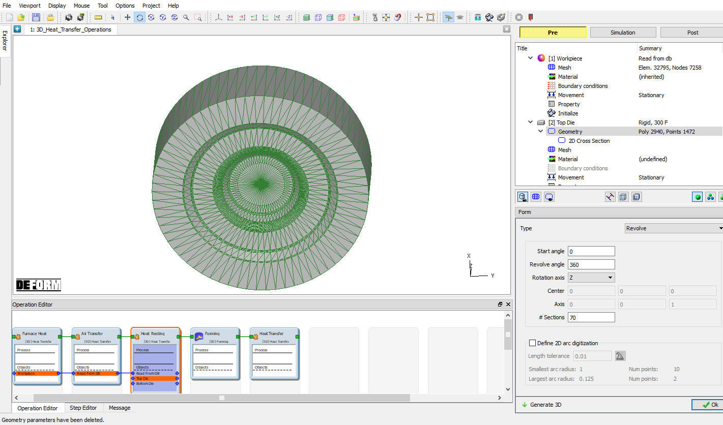
2d to 3d geometry conversion settings for top die
Generate Top Die Mesh
Click ![]() and generate mesh using default 32000 elements as shown in Fig. 3DHTRL1.32.
and generate mesh using default 32000 elements as shown in Fig. 3DHTRL1.32.
Generating mesh for Top die
Import Material for Dies
Click ![]() and load the material AISI-H13 from DEFORM Material library, from Die_material category using
and load the material AISI-H13 from DEFORM Material library, from Die_material category using ![]() (Load material data from library) option as shown in Fig. 3DHTRL1.33. Select the loaded material to assign it to the Top Die. Click on
(Load material data from library) option as shown in Fig. 3DHTRL1.33. Select the loaded material to assign it to the Top Die. Click on ![]() .
.
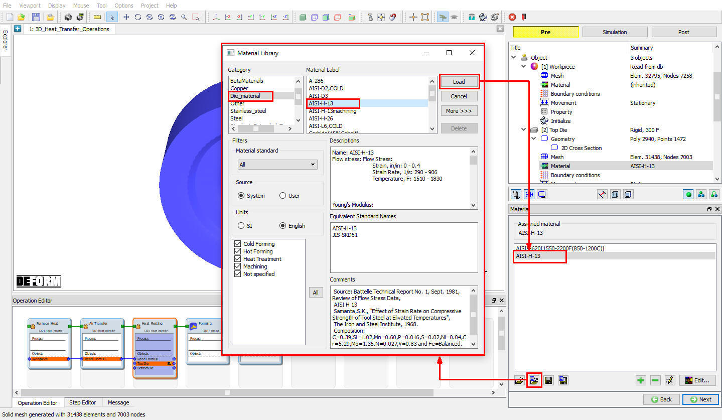
Loading Die material from DEFORM library
Define Top Die BCC
In the ‘Define BCC’ window, ‘Heat Exchange with Environment’ BCC automatically assigned to the all surfaces. Click on Defined branch under Heat Exchange with Environment BCC to confirm the BCC definition (see Fig. 3DHTRL1.34.). Click on Bottom Die branch in operation tree to define lower die.
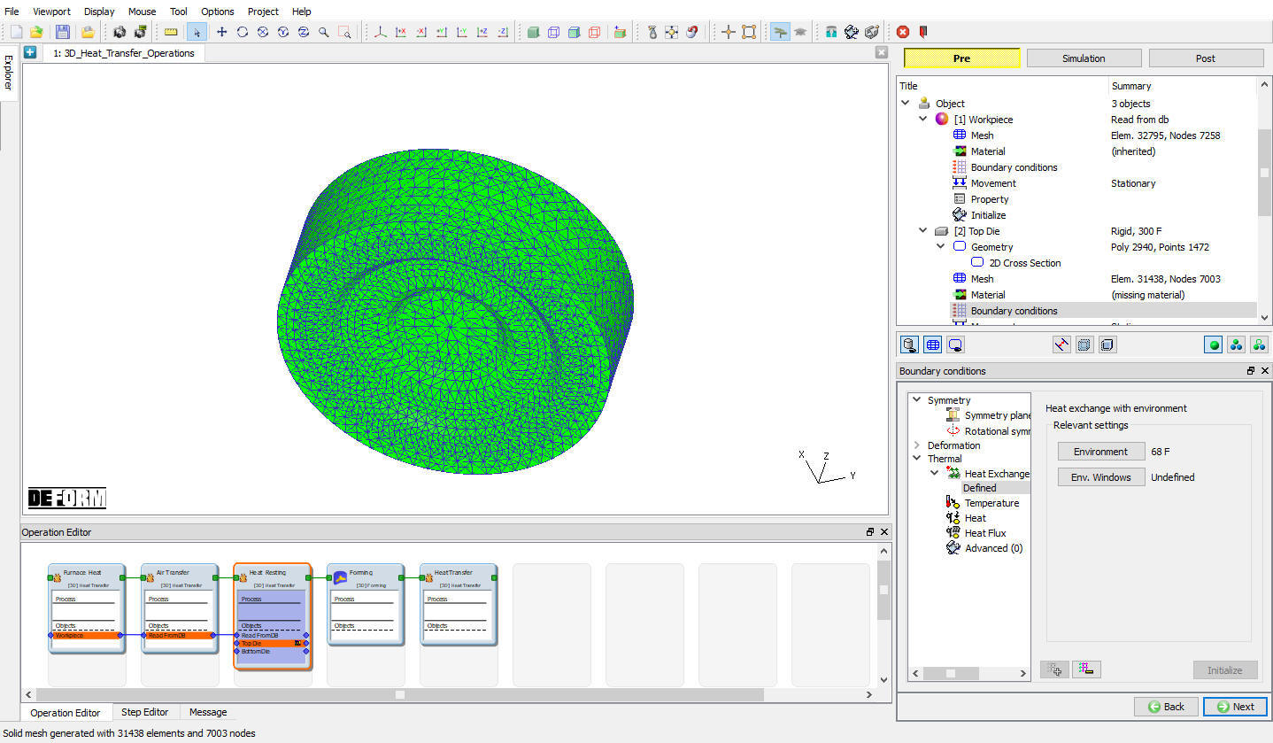
Heat exchange with Environment BCC for top die
Define Bottom Die
For Bottom die also accept 300F object temperature and Rigid object type as shown in Fig. 3DHTRL1.29. Click ![]() to continue.
to continue.
2D to 3D Geometry Conversion for Bottom Die
In Bottom die Geometry window check “Use cross section” checkbox (see Fig. 3DHTRL1.14.) and click ![]() to go to 2D geometry window, using
to go to 2D geometry window, using ![]() (Load Geometry from Library) button import ‘Disk_btm.igs’ from installation path /2D/LABS/ as shown in Fig. 3DHTRL1.35.
(Load Geometry from Library) button import ‘Disk_btm.igs’ from installation path /2D/LABS/ as shown in Fig. 3DHTRL1.35.
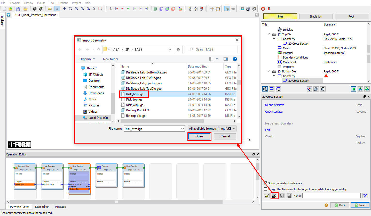
Loading Bottom die geometry from DEFORM library
After importing 2D geometry, click on ![]() and click on **2D- >3D Conversion
and click on **2D- >3D Conversion ![]() **option, revolve the 2d geometry about 360° along Z axis as shown in Fig. 3DHTRL1.36. Click on
**option, revolve the 2d geometry about 360° along Z axis as shown in Fig. 3DHTRL1.36. Click on![]() button and click on
button and click on ![]() to close the Conversion settings window.
to close the Conversion settings window.
2d to 3d geometry conversion settings for top die
Generate Bottom Die Mesh
Click ![]() and generate mesh using 32000 elements as shown in Fig. 3DHTRL1.37.
and generate mesh using 32000 elements as shown in Fig. 3DHTRL1.37.
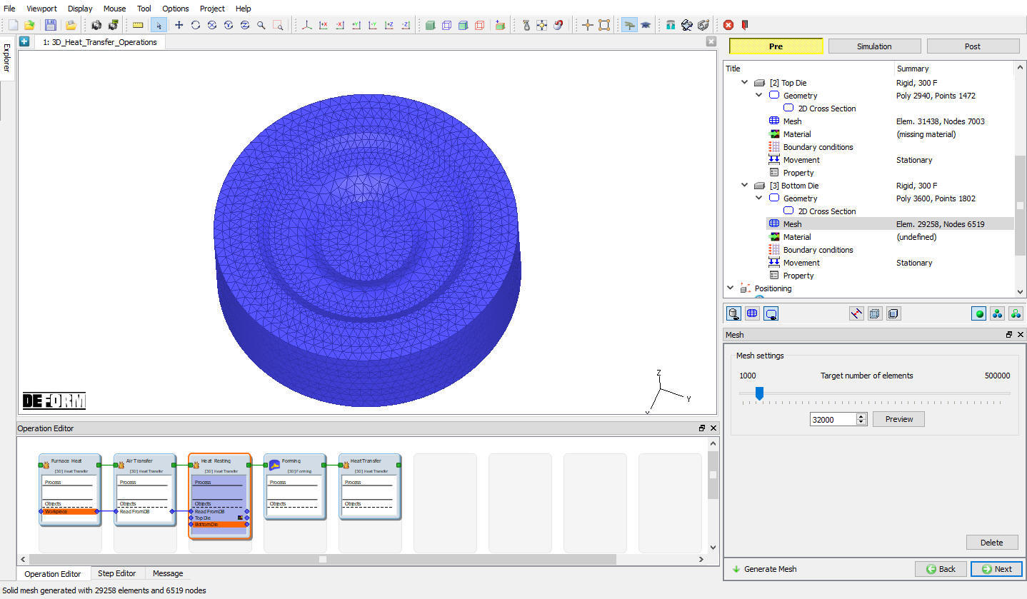
Generating mesh for bottom die
Assign Material for Bottom Die
SelectAISI-H13 material from material list to assign it to the Bottom Die.
Define Bottom Die BCC
Confirm the automatically assigned Heat Exchange with Environment BCC to all surfaces by clicking on ‘Defined’ under Heat exchange with Environment BCC as shown in Fig. 3DHTRL1.38. Click ![]() to continue.
to continue.
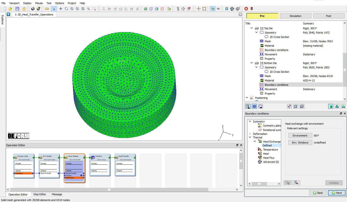
Heat exchange with Environment BCC for bottom die
Position Top Die
Now from the ‘Controls’ enter the ‘Position’ menu where we first move the top die away from the workpiece so that heat resting accounts for the heat transfer between workpiece and bottom die.
To accomplish this first click on ![]() button. Select the top die,
button. Select the top die,![]() method and distance vector as (x=0, y=0, z=4). Click on
method and distance vector as (x=0, y=0, z=4). Click on ![]() will move the top die away from the workpiece. (See Fig. 3DHTRL1.39.)
will move the top die away from the workpiece. (See Fig. 3DHTRL1.39.)
Click on ![]() to close the ‘Object Positioning window. Click
to close the ‘Object Positioning window. Click ![]() to define scheduled position the bottom die.
to define scheduled position the bottom die.
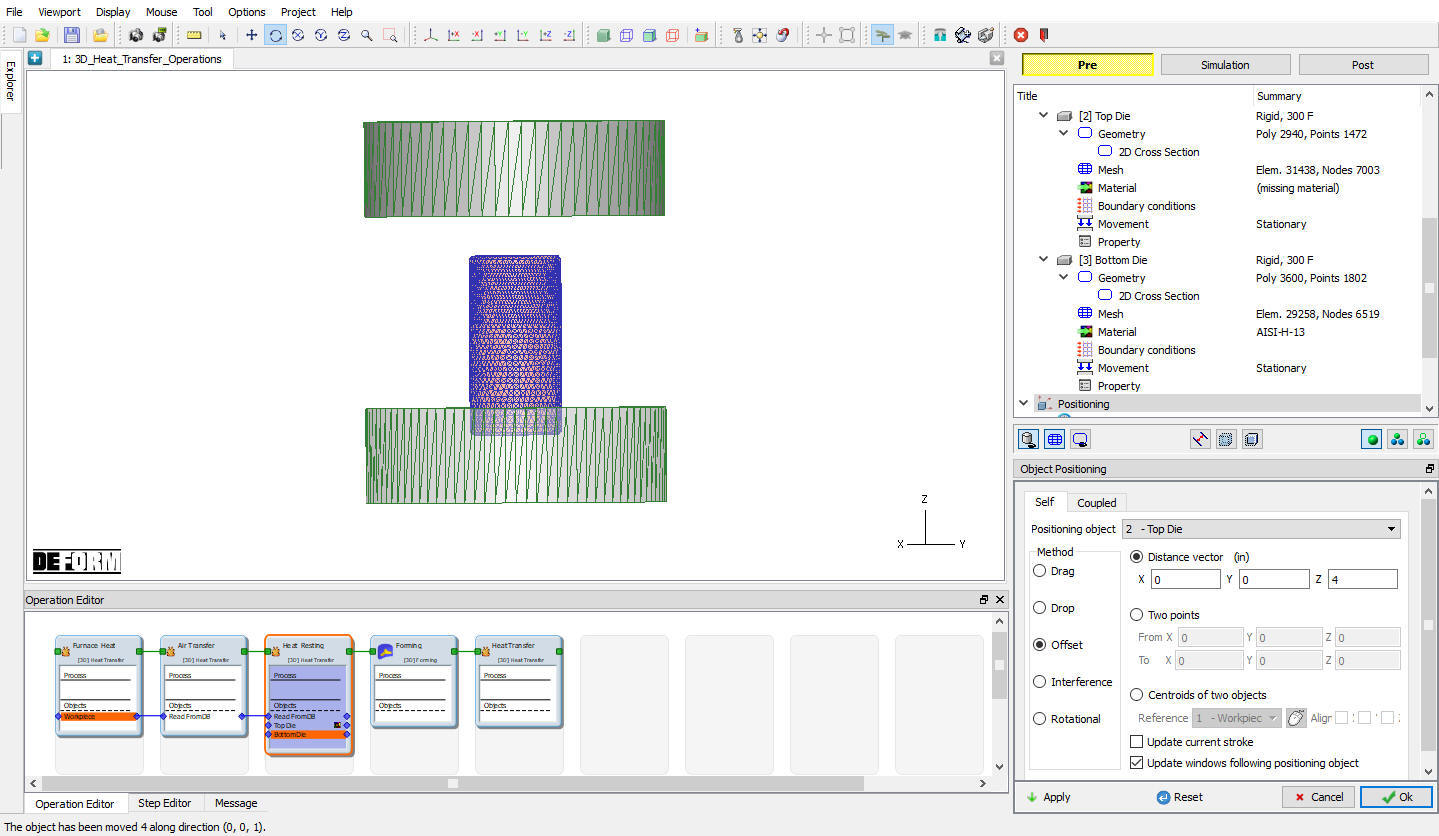
Positioning Top die in resting operation
Schedule Position Bottom Die
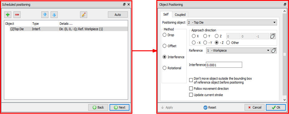
As Bottom die we need to position with respect to Read from DB object Workpiece, so we have to schedule position during DB generation. Click on ![]() (Add) button and select the ‘Positioning object’ as bottom die, method as ‘Interference’ with respect to ‘Workpiece’ in the +Z direction (See Fig. 3DHTRL1.40.). Note that, positioning details added in the scheduled positioning will be accounted prior to inter object data generation for this operation. No physical movement of the dies will be seen at this point. Click
(Add) button and select the ‘Positioning object’ as bottom die, method as ‘Interference’ with respect to ‘Workpiece’ in the +Z direction (See Fig. 3DHTRL1.40.). Note that, positioning details added in the scheduled positioning will be accounted prior to inter object data generation for this operation. No physical movement of the dies will be seen at this point. Click ![]() to continue.
to continue.
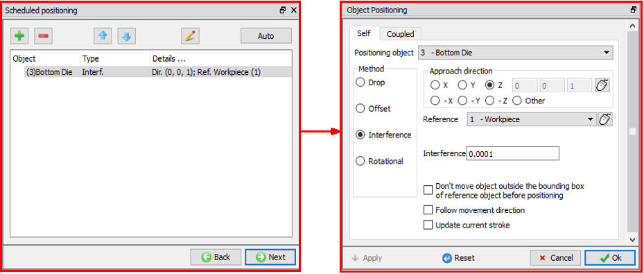
Scheduled positioning Bottom die with respect to workpiece
Schedule Inter-Object Contact Relationships for Heat Resting
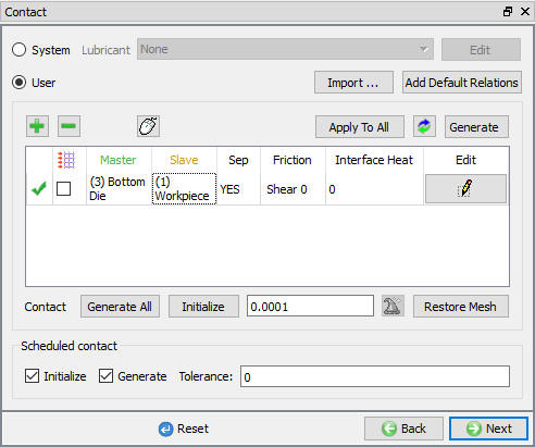
Select user type contact and click on ![]() (Add relationship) button and select Bottom die as Master and Workpiece as Slave as shown in Fig. 3DHTRL1.41.
(Add relationship) button and select Bottom die as Master and Workpiece as Slave as shown in Fig. 3DHTRL1.41.
Inter-object relationship between workpiece and bottom die
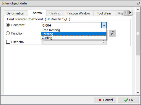
Click on ![]() (Edit) relationship button and select the pull down option “ F**r ee Resting**” in the thermal section to define the inter-object heat transfer coefficient as shown in Fig. 3DHTRL1.42. Click
(Edit) relationship button and select the pull down option “ F**r ee Resting**” in the thermal section to define the inter-object heat transfer coefficient as shown in Fig. 3DHTRL1.42. Click ![]() to close the Editing window. It will generate the inter-object contact at the beginning of the resting operation while simulating. Click on
to close the Editing window. It will generate the inter-object contact at the beginning of the resting operation while simulating. Click on ![]() until step controls window.
until step controls window.

Inter-object Heat transfer coefficient selection for resting
Define Step controls for Heat Resting
In Step Controls window, define number of steps as 10 ,step increment as 2 and solution step definition for each step as 0.4 sec as shown in Fig. 3DHTRL1.43. Click on ![]() to go to Generate DB window. In Database generation window, click on
to go to Generate DB window. In Database generation window, click on ![]() to open Forming operation.
to open Forming operation.
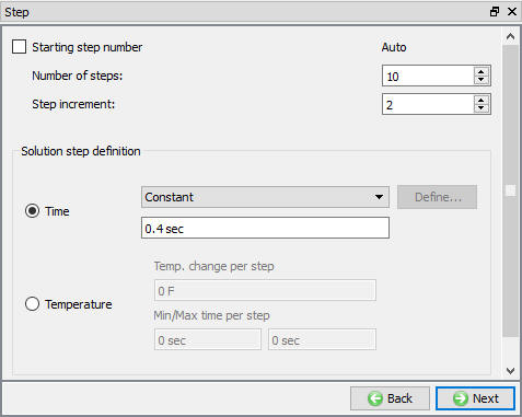
Step controls for heat resting operation
Operation4: Forming
The Forming operation runs for a specific stroke of (7.25”) the upper die. As we are making all objects as read from DB, objects data will come from previous operations, with thermal history. So pass the all objects from Heat resting operation to Forming operation as shown in Fig. 3DHTRL1.44.
Passing objects to read from DB
Select Simulation Modes for Forming
Click ![]() for Geometry type window and accept the Simulation controls default Simulation modes selected (Deformation and Heat transfer) as shown in Fig. 3DHTRL1.45. Click on
for Geometry type window and accept the Simulation controls default Simulation modes selected (Deformation and Heat transfer) as shown in Fig. 3DHTRL1.45. Click on ![]() until object window.
until object window.
Simulation controls settings for Forming operation
In objects page, confirm all objects data type as Read from DB and with no movement defined. In Object tree, click on Top Die- Movement branch to define top die movement controls.
Define Top Die Movement Controls
For Top die, assign constant die movement of 1 in/sec in the negative ‘Z’ direction as shown in Fig. 3DHTRL1.46. (Click preview object movement icon to view the movement of the top die, if the Step increment is defined).
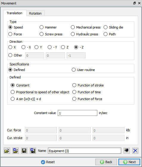
Movement controls for Top die
Schedule Position Top Die
Click on Scheduled positioning branch in Object tree to define the positioning for Top die. Now click on ![]() (Add) button and select the ‘Positioning object’ asT**o p die,** method as ‘Interference ’ with respect to ‘Workpiece ’ in the -Z direction (see Fig. 3DHTRL1.47.). Click
(Add) button and select the ‘Positioning object’ asT**o p die,** method as ‘Interference ’ with respect to ‘Workpiece ’ in the -Z direction (see Fig. 3DHTRL1.47.). Click ![]() to continue.
to continue.
Scheduled positioning for Top die in forming operation
Schedule Inter-Object Contact Relationships for Forming
Select user type contact and click on ![]() button. It will add the relationship between the Billet, Top Die and Bottom Die (see Fig. 3DHTRL1.49.). As the Dies are Rigid and Billet is plastic, Top and Bottom Dies are considered as Master and Billet as Slave. In order to predict the fold during deformation, self contact will be assigned for Billet.
button. It will add the relationship between the Billet, Top Die and Bottom Die (see Fig. 3DHTRL1.49.). As the Dies are Rigid and Billet is plastic, Top and Bottom Dies are considered as Master and Billet as Slave. In order to predict the fold during deformation, self contact will be assigned for Billet.
Highlight the Top Die – Billet relationship and click the ![]() button to modify the contact conditions. In the friction section of the screen (see Fig. 3DHTRL1.48.), there is a pull-down menu that allows the user to choose the appropriate friction conditions of common forming processes.
button to modify the contact conditions. In the friction section of the screen (see Fig. 3DHTRL1.48.), there is a pull-down menu that allows the user to choose the appropriate friction conditions of common forming processes.
Since this is hot forming simulation and the dies are steel, use the pull down menu and select Hot forming (lubricated) from the list. A friction value of 0.3 will automatically be selected.
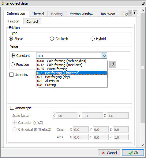
Inter-object friction coefficient definition window
The Thermal data needs to be modified so that a ‘Forming’ heat transfer coefficient is used instead of the ‘Free resting’ coefficient used in the previous operation. Click on Thermal tab and Select Forming in pull down menu as shown in Fig. 3DHTRL1.49.
Inter-object friction coefficient definition window
Click ![]() to go back to Inter-Object window, Since the friction conditions are the same for all the object pairs, the
to go back to Inter-Object window, Since the friction conditions are the same for all the object pairs, the ![]() button can be used to copy the interface properties from the first relationship to all of the others. After this is done, all relationships will have a friction of 0.3 defined as shown in Fig. 3DHTRL1.50. Since the contact will initialize and generate while generating database. Click
button can be used to copy the interface properties from the first relationship to all of the others. After this is done, all relationships will have a friction of 0.3 defined as shown in Fig. 3DHTRL1.50. Since the contact will initialize and generate while generating database. Click ![]() to continue.
to continue.

Inter-Object relationship definition for forming operation
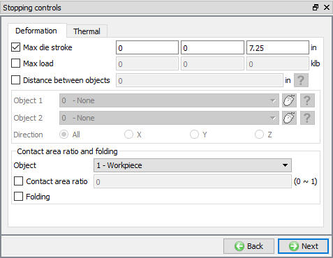
Define Stopping Control for Forming
In stopping control window check the Max. die stroke stopping control and define primary die displacement as (0,0,7.25) as shown in Fig. 3DHTRL1.51. Advanced stopping options are available in Expert mode (![]() ). Click on
). Click on ![]() to define the step controls.
to define the step controls.
Die stroke stopping control for forming operation
Define Step Controls for Forming
In step controls window, define number of steps as 100 at 0.0725 ” per step of die movement, step incrementtosave as 10 for the primary die (which is object number 2 in this simulation) as shown in Fig. 3DHTRL1.52.
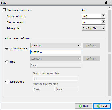
Step controls settings for forming operation
Click ![]() and click on
and click on ![]() button to open Heat Dwelling operation.
button to open Heat Dwelling operation.
Operation5: Heat Dwelling
Heat dwelling is nothing but heat transfer after the deformation operation for a particular time and the corresponding time is called heat dwelling time or simply dwell time.
Select the Heat Transfer Type for Heat Dwelling
Name the Operation as heat Dwelling and select the ‘Dwell on die’ heat transfer type radio button as shown in Fig. 3DHTRL1.53.
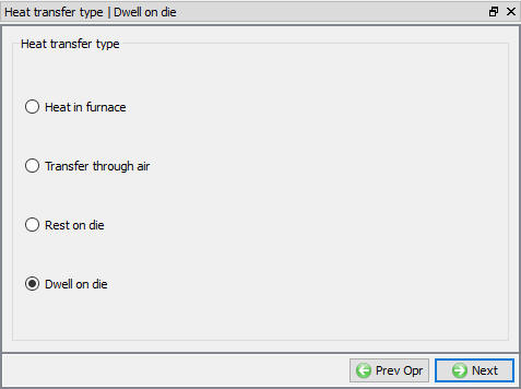
Heat transfer type for Heat Dwelling operation
Set Process Condition for Heat Dwelling
Click ![]() and accept the Dwelltime of 4 sec in Environment temperature 68F and default Convection coefficient as shown in Fig. 3DHTRL1.54.
and accept the Dwelltime of 4 sec in Environment temperature 68F and default Convection coefficient as shown in Fig. 3DHTRL1.54.
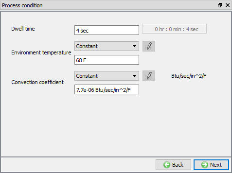
Process condition settings for Heat Dwelling operation
The default data is set for all the objects are read from DB (coming from the previous operations, along with thermal history). Accept the default conditions for the objects and click ![]() to proceed until Contact (Inter-Object Contact) window.
to proceed until Contact (Inter-Object Contact) window.
Schedule Inter-Object Contact Relationships for Heat Dwelling
Select usertype contact and click on ![]() button. Highlight the Top Die – Billet relationship and click the
button. Highlight the Top Die – Billet relationship and click the ![]() button to modify the contact conditions. Select the pull down option “Free Resting “ in the thermal section to define the inter-object heat transfer coefficient as shown in Fig. 3DHTRL1.42.
button to modify the contact conditions. Select the pull down option “Free Resting “ in the thermal section to define the inter-object heat transfer coefficient as shown in Fig. 3DHTRL1.42.
Click on ![]() button and click
button and click ![]() to close the Editing window (see Fig. 3DHTRL1.55.). It will generate the inter-object contact during database generation. Click
to close the Editing window (see Fig. 3DHTRL1.55.). It will generate the inter-object contact during database generation. Click ![]() until step controls window.
until step controls window.
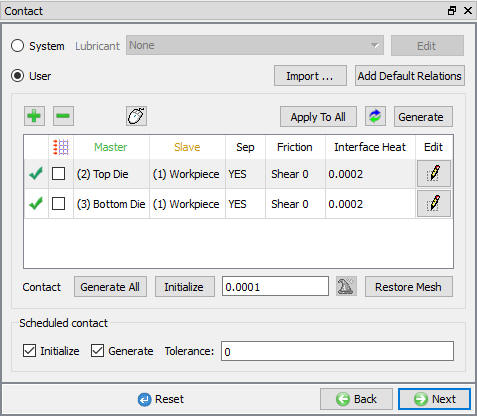
Inter-object contact relationship for heat dwelling operation
Define Step Controls for Heat Dwelling
In Step Controls window, define number of steps as 10 , stepincrement as 2 and solution step definition for each step as 0.4 sec. (See Fig. 3DHTRL1.56.). This completes the multiple operations with all heat transfer operations setup. Switch to ![]() tab to simulate the problem.
tab to simulate the problem.
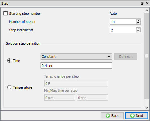
Step controls for heat dwelling operation
Simulate problem
Click on the ![]() action label to open the Run Options dialog as shown in Fig. 3DHTRL1.57. Use the default Continue Run option to select “Continue from the last step ” option and then select the Simulation mode as Interactive and click on
action label to open the Run Options dialog as shown in Fig. 3DHTRL1.57. Use the default Continue Run option to select “Continue from the last step ” option and then select the Simulation mode as Interactive and click on ![]() button to run the simulation.
button to run the simulation.
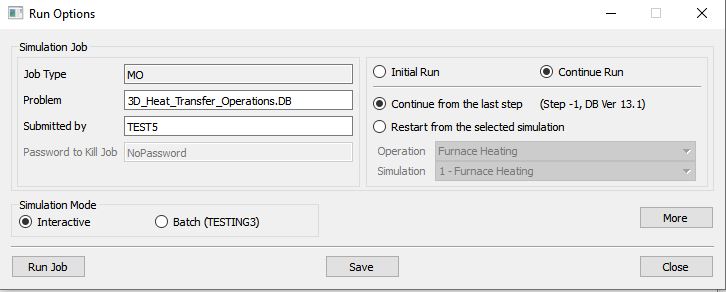
Run Simulation popup window
Monitor the progress of the simulation by looking at the Simulation Graphics, Simulation Message and Simulation Log tab, make sure that the ![]() option is checked. (See Fig. 3DHTRL1.58.)
option is checked. (See Fig. 3DHTRL1.58.)
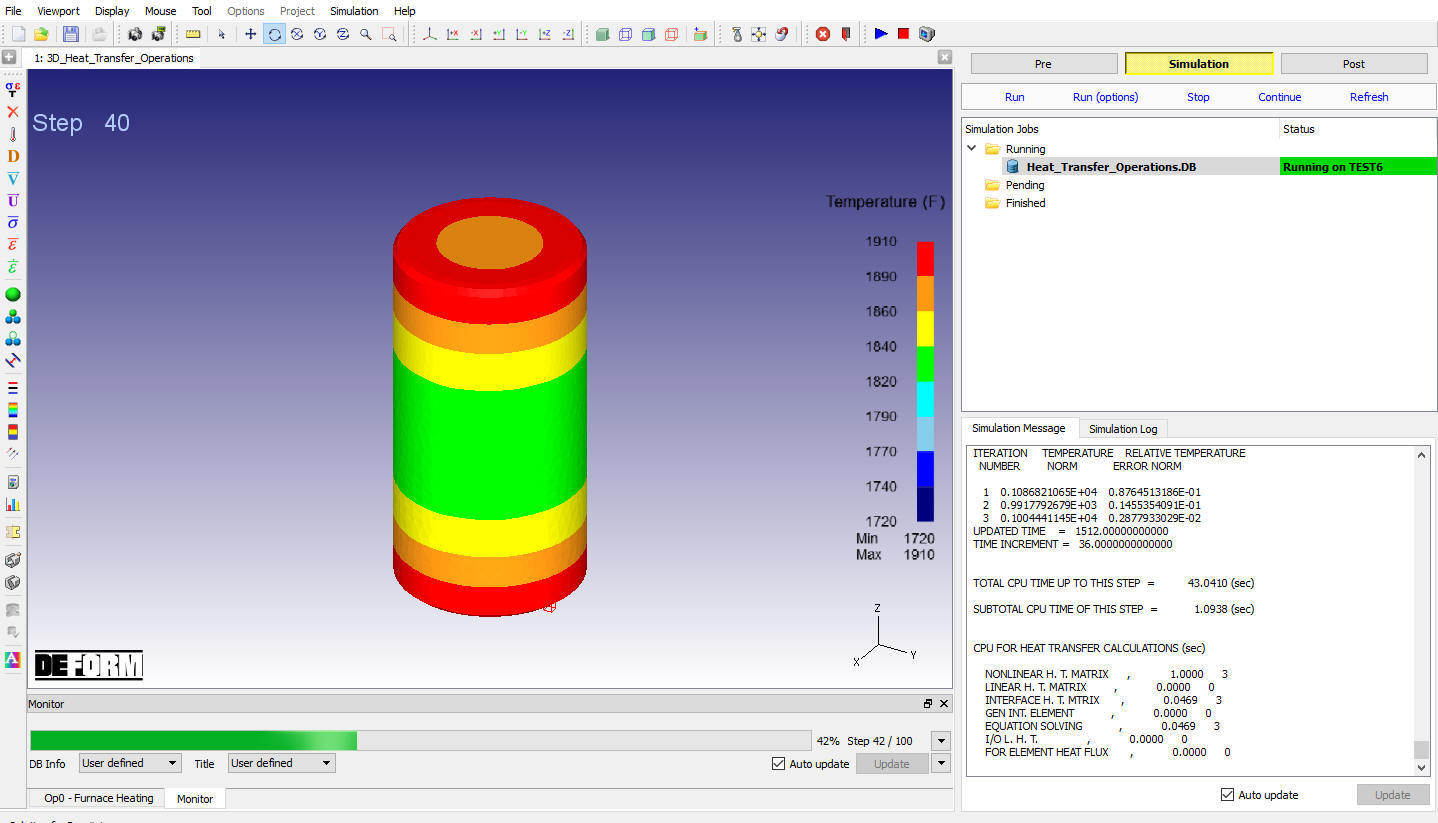
Simulation mode displaying the furnace heating running status
After completion of all multiple operations, in Simulation log file, it gives the log message as “MULTIPLE OPERATION COMPLETED.”, then switch to ![]() tab to view the simulation results.
tab to view the simulation results.
Post Processing
In post processor, Step list below the graphic area indicates step numbers available from the different operations simulated. A set of state variables available from the ‘Post’ menu can be used to review the model response. Please note that, for the first two operations, only thermal data of the workpiece is available as the dies are introduced from the third operation. And the deformation results can be viewed for Deformation operation (See Fig. 3DHTRL1.59.)
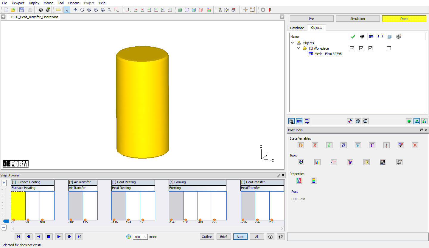
MO Post processor after simulating all operations
Some important state variables can be selected directly from ‘Post Tools’ window and the rest can be accessed through State Variable dialog by clicking on ![]() icon. (See Fig. 3DHTRL1.60.)
icon. (See Fig. 3DHTRL1.60.)
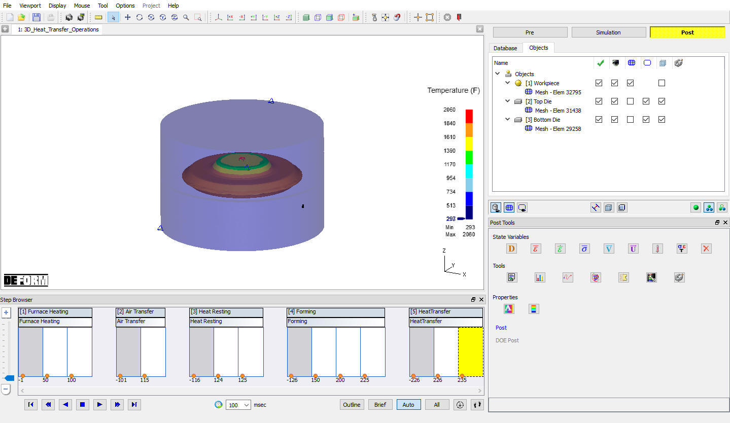
Temperature plot for all objects at the end of multiple operations
Plot Temperature state variable and play the steps from first operation to observe the heat transfer in workpiece and dies from Furnace heating to Heat dwelling operation as shown in Fig. 3DHTRL1.61.
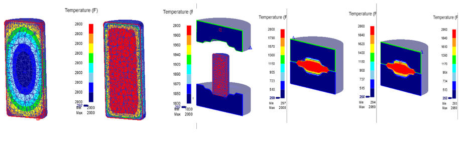
Hat transfer in objects from furnace heating to heat dwelling operation